
Related Manuals for Optimum BF20 V


Summary of Contents for Optimum BF20 V
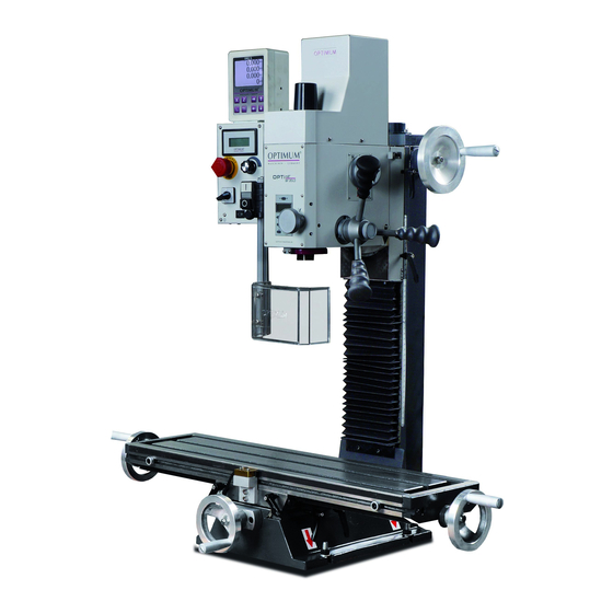
- Page 1 OPTIMUM M A S C H I N E N - G E R M A N Y Operating manual Version 3.1.8 Mill Drill Article no. 3338128 115V, 1- Phase Optional Stand, Item No. 3353003...
-
Page 2: Table Of Contents
OPTIMUM M A S C H I N E N - G E R M A N Y Table of contents Safety Type plate ..............................5 Safety instructions (warning notes)......................6 1.2.1 Classification of hazards...........................6 1.2.2 Other pictograms ............................7 Proper use ..............................8 Reasonably foreseeable misuses......................8... - Page 3 OPTIMUM M A S C H I N E N - G E R M A N Y Control and indicating elements ......................23 4.2.1 Control panel ............................24 Switching on the mill drill ........................25 Switching off the mill drill ........................25 Inserting a tool............................
- Page 4 Dear customer, Thank you very much for purchasing a product made by OPTIMUM. OPTIMUM metal working machines offer a maximum of quality, technically optimum solutions and convince by an outstanding price performance ratio. Continuous enhancements and product innovations guarantee state-of-the-art products and safety at any time.
-
Page 5: Safety
OPTIMUM M A S C H I N E N - G E R M A N Y Safety This part of the operating instructions explains the meaning and use of the warning references contained in the operating manual, ... -
Page 6: Safety Instructions (Warning Notes)
OPTIMUM M A S C H I N E N - G E R M A N Y Safety instructions (warning notes) 1.2.1 Classification of hazards We classify the safety warnings into various levels. The table below gives an overview of the classification of symbols (ideogram) and the warning signs for each specific danger and its (possible) consequences. -
Page 7: Other Pictograms
OPTIMUM M A S C H I N E N - G E R M A N Y 1.2.2 Other pictograms Warning risk of stumbling! Warning of flammable sub- Warning of suspended loads! Activation forbidden! stances! Warning tilting danger! Warning of biological hazard! Read the operating instruc-... -
Page 8: Proper Use
Optimum Maschinen Germany GmbH then the mill drill is being used improperly. We will not be held liable for any damages resulting from any operation which is not in accord- ance with the intended use. -
Page 9: Possible Dangers Caused By The Mill Drill
OPTIMUM M A S C H I N E N - G E R M A N Y ATTENTION! The workpiece is always to be fixed by a machine vice, jaw chuck or by another appropriate clamping tool such as for the clamping claws. -
Page 10: Qualification Of Personnel
OPTIMUM M A S C H I N E N - G E R M A N Y INFORMATION Everyone involved in the assembly, commissioning, operation and maintenance must be duly qualified, strictly follow these operating instructions. Always disconnect the mill drill from the electrical power supply when performing cleaning or maintenance works. -
Page 11: Operator Positions
OPTIMUM M A S C H I N E N - G E R M A N Y INFORMATION Everyone involved in the assembly, commissioning, operation and maintenance must be duly qualified, strictly follow these operating instructions. In the event of improper use ... -
Page 12: Emergency-Stop Push Button
OPTIMUM M A S C H I N E N - G E R M A N Y WARNING! The separating protective equipment which is made available and delivered together with the machine is designed to reduce the risk of workpieces or fractions of them which being expelled, but not to remove them completely. -
Page 13: Separating Protective Equipment
OPTIMUM M A S C H I N E N - G E R M A N Y 1.9.3 Separating protective equipment Adjust the protective equipment to the correct height before you start working. Clamping screw To do so, detach the clamping screw, adjust the required height and re-tighten the clamping screw. -
Page 14: Personal Protective Equipment
OPTIMUM M A S C H I N E N - G E R M A N Y 1.11 Personal protective equipment For certain work personal protective equipment is required. Protect your face and your eyes: Wear a safety helmet with facial protection when performing works where your face and eyes are exposed to hazards. -
Page 15: Technical Data
OPTIMUM M A S C H I N E N - G E R M A N Y Technical data The following information are the dimensions and indications of weight and the manufacturer‘s approved machine data. Power Suply Motor 1.2 HP, 115V, 1 Ph, 60 Hz... -
Page 16: Emissions
OPTIMUM M A S C H I N E N - G E R M A N Y Reduction stage fast 150 - 3,000 RPM Environmental conditions Temperature 5 - 35 °C/ 40 - 95 F Humidity 25 - 80% 2.10... -
Page 17: Dimensions, Installation Plan Bf20V
OPTIMUM M A S C H I N E N - G E R M A N Y 2.12 Dimensions, installation plan BF20V Img.2-1: installation plan BF20V BF20V Version 3.1.8 dated 2015-1-27 Original operating instructions Page 17... -
Page 18: Installation Plan Of Optional Stand
OPTIMUM M A S C H I N E N - G E R M A N Y 2.13 Installation plan of optional stand Img.2-2: installation plan stand 3353003 BF20V Page 18 Original operating instructions Version 3.1.8 dated 2015-1-27... -
Page 19: Unpacking And Connecting
OPTIMUM M A S C H I N E N - G E R M A N Y Unpacking and connecting INFORMATION The mill drill is pre assembled. Scope of delivery Check immediately upon delivery of the mill drill if there are any transport damages or loos- ened fastening screws. -
Page 20: Storage
OPTIMUM M A S C H I N E N - G E R M A N Y Storage ATTENTION! In case of wrong and improper storage electrical and mechanical machine components might get damaged and destroyed. Store packed and unpacked parts only under the intended environmental conditions. -
Page 21: Load Suspension Point
OPTIMUM M A S C H I N E N - G E R M A N Y Also consider that the machine is accessible for setting and maintenance works. Provide for sufficient illumination (Minimum value: 47 lumens/FT , measured at the tool tip). -
Page 22: Power Supply
M A S C H I N E N - G E R M A N Y It is only allowed to modify tool holding fixtures in compliance with the recommendations of OPTIMUM or the manufacturer of the clamping device. WARNING! When first commissioning the mill drill by inexperienced staff you endanger people and the machine. -
Page 23: Operation
OPTIMUM M A S C H I N E N - G E R M A N Y Operation Safety Commission the mill drill only under the following conditions: The mill drill is in proper working order. The mill drill is used as prescribed. -
Page 24: Control Panel
OPTIMUM M A S C H I N E N - G E R M A N Y 4.2.1 Control panel Fig.4-2: control panel, front view Fig.4-3: Control panel, back Pos. Description Pos. Description Clamping screw of spindle quill Digital display speed... -
Page 25: Switching On The Mill Drill
OPTIMUM M A S C H I N E N - G E R M A N Y Main switch Switches the voltage supply on. The main switch is at the back of the control panel. Hand-actuated auxiliary switch Start / Stop Switches the machine on or off. -
Page 26: Inserting A Tool
OPTIMUM M A S C H I N E N - G E R M A N Y Inserting a tool 4.5.1 Installation CAUTION! When milling operations are performed the cone seat has to be fixed always to the draw- in rod. -
Page 27: Clamping The Workpieces
The optimum cutting speed mainly depends on the material and on the material of the tool. With tools (milling cutters) made of hard metal or ceramic insert it is possible to work at higher speeds than with tools made of high-alloyed high-speed steel (HSS). -
Page 28: Standard Values For Cutting Speeds
OPTIMUM M A S C H I N E N - G E R M A N Y 4.8.1 Standard values for cutting speeds [FPM] with high-speed steel and hard metal in conventional milling Age- Hardened Tool Steel Grey Cast Iron... -
Page 29: Standard Values For Speeds With Hss - Eco - Twist Drilling (U.s. Unit)
OPTIMUM M A S C H I N E N - G E R M A N Y 4.8.2 Standard values for speeds with HSS – Eco – twist drilling (U.S. unit Coolant Cutter Diameter (in.) Material 0,0787 0,1181 0,1575 0,1969 0,2362 0,2756 0,3150 0,3543 0,3937 5.600... -
Page 30: Manual Spindle Feed With The Fine Feed
OPTIMUM M A S C H I N E N - G E R M A N Y Manual spindle feed with the fine feed Turn the handle screw. The spindle lever will move towards the mill drill head and will activate the clutch of the fine feed. -
Page 31: Troubleshooting
OPTIMUM M A S C H I N E N - G E R M A N Y Operation mode "S" The operation mode "S" is used to enter and to compensate the backlash of quill mechanism. (1) Display which shows the operating modes "S", "inch" or "mm"... -
Page 32: Swivelling The Mill Drill Head
OPTIMUM M A S C H I N E N - G E R M A N Y 4.12 Swivelling the mill drill head The mill drill head may be swivelled to the Clamping screws right and to the left. Two clamping screws need to be loosened. -
Page 33: Maintenance
OPTIMUM M A S C H I N E N - G E R M A N Y Maintenance In this chapter you will find important information about Inspection Maintenance Repair of the mill drill. ATTENTION ! Properly performed regular maintenance is an essential prerequisite for ... - Page 34 OPTIMUM M A S C H I N E N - G E R M A N Y Interval Where? What? How? Lubricate all slideways. Start of work, after every Oiling maintenance or repair work Oil all bare steel surfaces. Use an acid-free oil, e.g.
- Page 35 OPTIMUM M A S C H I N E N - G E R M A N Y Interval Where? What? How? Lamp holder Halogen pin base lamp Lamp cover Replacing the As required halogen lamp Fig.5-3: Replacing the halogen lamp ...
-
Page 36: Repair
Should technical assistance be required, contact LDS Industries at (630) 785-6437. Optimum Maschinen - Germany and LDS Industries are not liable for, nor do they guarantee against, damage or operating malfunctions resulting from alteration, abuse, lack of main- tenance or this product’s use for other than its intended purpose. -
Page 37: Spare Parts Bf20 Vario
OPTIMUM M A S C H I N E N - G E R M A N Y Spare parts BF20 Vario Cross table 57-2 57-1 57-1 57-2 57-1 57-2 Fig.6-1: Cross table BF20V Version 3.1.8 2015-1-27 Original operating instructions... -
Page 38: Column 1 Of 2
OPTIMUM M A S C H I N E N - G E R M A N Y Column 1 of 2 Fig.6-2: Column 1 of 2 BF20V Original operating instructions Version 3.1.8 2015-1-27... -
Page 39: Column 2 Of 2
Column 2 of 2 Fig.6-3: Column 2 of 2... -
Page 40: Milling Head 1 Of 2
OPTIMUM M A S C H I N E N - G E R M A N Y Milling head 1 of 2 Fig.6-4: Milling head 1 of 2 BF20V Original operating instructions Version 3.1.8 2015-1-27... -
Page 41: Milling Head 2 Of 2
OPTIMUM M A S C H I N E N - G E R M A N Y Milling head 2 of 2 Fig.6-5: Milling head 2 of 2 BF20V Version 3.1.8 2015-1-27 Original operating instructions... -
Page 42: Operation Panel And Protection Device
OPTIMUM M A S C H I N E N - G E R M A N Y Operation panel and protection device Fig.6-6: Operation panel and protection device BF20V Original operating instructions Version 3.1.8 2015-1-27... -
Page 43: Optional Sub Structure
OPTIMUM M A S C H I N E N - G E R M A N Y Optional sub structure Fig.6-7: Sub structure BF20V Version 3.1.8 2015-1-27 Original operating instructions... -
Page 44: Wiring Diagram
OPTIMUM M A S C H I N E N - G E R M A N Y Wiring diagram 115V ~ 60Hz Fig.6-8: Wiring diagram BF20V Original operating instructions Version 3.1.8 2015-1-27... -
Page 45: Spare Part List
OPTIMUM M A S C H I N E N - G E R M A N Y 6.8.1 Spare part list Description Qty. Drawing no. Size Article no. Connect board DM14-01-14 0333812001 Socket head set screw GB 79-85 M6 x 16... - Page 46 OPTIMUM M A S C H I N E N - G E R M A N Y Description Qty. Drawing no. Size Article no. Table lead screw nut x axis DM14-02-09 0333812066y Hexagon head cap screw GB 70-85 M4 x 20...
- Page 47 OPTIMUM M A S C H I N E N - G E R M A N Y Description Qty. Drawing no. Size Article no. Grooved ball bearing 6007-2Z 6007-2Z 0406007.2R Retainer ring DIN 471 15 x 1 03338120208 Z 37, m 1,25,...
- Page 48 OPTIMUM M A S C H I N E N - G E R M A N Y Description Qty. Drawing no. Size Article no. Hexagon head cap srew GB 70-85 M3 x 6 Angle sensor 03338120277 Hexagon head cap screw...
-
Page 49: Troubleshooting
OPTIMUM M A S C H I N E N - G E R M A N Y Troubleshooting Troubleshooting the mill drill Cause/ Malfunction Solution possible consequences The mill drill does not start • Start sequence not followed. -
Page 50: Appendix 8.1 Copyright
OPTIMUM M A S C H I N E N - G E R M A N Y Appendix Copyright This document is copyright. All derived rights are also reserved, especially those of translation, re-printing, use of figures, broadcast, reproduction by photo-mechanical or similar means and recording in data processing systems, neither partial nor total. -
Page 51: Limited Warranty
OPTIMUM assumes no obligations or liability on account of any unauthorized recommendations, opinions or advice as to the choice, installation or use of products. - Page 52 M A S C H I N E N - G E R M A N Y EC - Declaration of Conformity Machinery Directive 2006/42/EC Annex II 1.A The manufacturer / Optimum Maschinen Germany GmbH Dr.-Robert-Pfleger-Str. 26 retailer: D - 96103 Hallstadt...
- Page 53 OPTIMUM M A S C H I N E N - G E R M A N Y Index Assembly ............21 Changing the speed range ........27 Cleaning and lubricating ........22 Control panel ............24 Copyright .............50 Digital display ............30 Disassembly ............26 EC - Declaration of Conformity ......52...
- Page 54 OPTIMUM M A S C H I N E N - G E R M A N Y BF20V Page 54 Original operating instructions Version 3.1.8 dated 2015-1-27...
Need help?
Do you have a question about the BF20 V and is the answer not in the manual?
Questions and answers