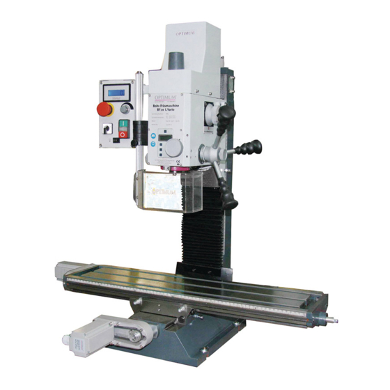
Optimum BF20 L Vario Operating Manual
Drilling-milling machine
Hide thumbs
Also See for BF20 L Vario:
- Assembly and maintenance instructions (42 pages) ,
- Modification instructions (61 pages)
Table of Contents

Related Manuals for Optimum BF20 L Vario


Summary of Contents for Optimum BF20 L Vario
- Page 1 M A S C H I N E N - G E R M A N Y Operating manual Version 3.1.4 Drilling-Milling machine BF20 Vario BF20 L Vario Keep for future reference! 8 / 03 / 2010 Version 3.1.4 BF 20 Vario ; BF 20 L Vario...
-
Page 2: Table Of Contents
Table of Contents Preface We thank you very much that you have decided for the drilling-milling machine made by Optimum Maschinen Germany GmbH. Changes The illustration of the drilling-milling machine might in some details deviate from the illustrations of this operating manual but this will have no influence on the operation of the drilling-milling machine. - Page 3 OPTIMUM M A S C H I N E N - G E R M A N Y Optional accessory........................ 24 Operation Safety ............................ 25 Control and indicating elements .................... 25 4.2.1 Control panel......................26 Switching on the drilling-milling machine................28 Switching off the drilling-milling machine................
- Page 4 Disposal ..........................64 RoHS , 2002/95/CE....................... 64 Product follow-up ........................65 EC - Declaration of Conformity BF20 Vario ................66 EC - Declaration of Conformity BF20 L Vario ............... 67 Index Page 4 Drilling-Milling machine BF 20 Vario ; BF 20 L Vario Version 3.1.4...
-
Page 5: Safety
Always keep this documentation close to the drilling-milling machine. INFORMATION If you are unable to solve a problem using this manual, please contact us for advice: Optimum Maschinen Germany GmbH Dr. Robert-Pfleger-Str. 26 D- 96103 Hallstadt Telefon: +49 (0) 900 - 19 68 220 (0,49 €/min.) E-Mail: info@optimum-maschinen.de... -
Page 6: Safety Warnings (Warning Notes)
OPTIMUM Safety M A S C H I N E N - G E R M A N Y Safety warnings (warning notes) 1.1.1 Classification of hazards We classify the safety warnings into various levels. The table below gives an overview of the classification of symbols (pictograms) and warnings for the specific danger and its (possible) consequences. -
Page 7: Further Pictograms
If the drilling-milling machine is used in any way other than described above, modified without the authorisation of the company Optimum Maschinen Germany GmbH or operated with diffe- rent process data, then the drilling-milling machine is being used improperly. -
Page 8: Possible Dangers Caused By The Drilling-Milling Machine
OPTIMUM Safety M A S C H I N E N - G E R M A N Y WARNING! Very serious injury due to improper use. It is forbidden to make any modifications or alterations to the operating values of the drilling-milling machine. -
Page 9: Safety Measures During Operation
OPTIMUM Safety M A S C H I N E N - G E R M A N Y INFORMATION All persons involved in assembly, commissioning, operation and maintenance must be duly qualified, strictly follow this operating manual. In the event of improper use... -
Page 10: Emergency-Stop Button
OPTIMUM Safety M A S C H I N E N - G E R M A N Y WARNING! The separating protective equipment which is made available and delivered together with the machine is designed to reduce the risk of workpieces or fractions of them which being expelled, but not to remove them completely. -
Page 11: Separating Protective Equipment
OPTIMUM Safety M A S C H I N E N - G E R M A N Y 1.6.3 Separating protective equipment Adjust the protective equipment to the correct height before you start working. Locking screw To do so, detach the clamping screw, adjust the required height and retighten the clamping screw. -
Page 12: Personnel Protective Equipment
OPTIMUM Safety M A S C H I N E N - G E R M A N Y Personnel protective equipment For certain work peersonnel protective equipment is required. : During all work and specifically work during which your face and eyes Protect your face and eyes are exposed to hazards, a safety helmet with a face guard should be worn. -
Page 13: Disconnecting And Securing The Drilling-Milling Machine
OPTIMUM Safety M A S C H I N E N - G E R M A N Y 1.10 Disconnecting and securing the drilling-milling machine Pull out the mains plug before starting maintenance and repair work. 1.11 Using lifting equipment... -
Page 14: Rescuing Persons In Dangerous Situations After The Cnc Retrofitting
OPTIMUM Safety M A S C H I N E N - G E R M A N Y 1.13 Rescuing persons in dangerous situations after the CNC retrofitting If the machine was subject to a subsequent retrofitting with CNC controlled drives, the following additional dangerous situations such as squeezing and sticking of parts of the body may result hereof. -
Page 15: Technical Data
M A S C H I N E N - G E R M A N Y Technical data The following information gives the dimensions and weight and is the manufacturer’s authorised machine data. Power connection BF20 Vario BF20 L Vario Engine 230 V / 50Hz / 850 W Drilling-milling capacity BF20 Vario BF20 L Vario Ø... -
Page 16: Emissions
Technical data M A S C H I N E N - G E R M A N Y Reduction stage fast [min 150 - 3000 Environmental BF20 Vario BF20 L Vario conditions Temperature 5-35 °C Humidity 25 - 80% 2.10... -
Page 17: Installation Plan Bf 20 Vario
OPTIMUM Technical data M A S C H I N E N - G E R M A N Y 2.12 Installation plan BF 20 Vario Abb.2-1: Installation plan BF 20 Vario 8 / 03 / 2010 Version 3.1.4 BF 20 Vario ; BF 20 L Vario... -
Page 18: Installation Plan Bf 20L Vario
OPTIMUM Technical data M A S C H I N E N - G E R M A N Y 2.13 Installation plan BF 20L Vario Abb.2-2: Installation plan BF 20L Vario Page 18 Drilling-Milling machine BF 20 Vario ; BF 20 L Vario Version 3.1.4... -
Page 19: Installation Plan Of Optional Substructure
OPTIMUM Technical data M A S C H I N E N - G E R M A N Y 2.14 Installation plan of optional substructure Abb.2-3: Substructure 3353003 8 / 03 / 2010 Version 3.1.4 BF 20 Vario ; BF 20 L Vario... -
Page 20: Unpacking And Connecting
OPTIMUM Unpacking and connecting M A S C H I N E N - G E R M A N Y Unpacking and connecting INFORMATION The drilling-milling machine comes pre-assembled. Extent of supply When the drilling-milling machine is delivered, immediately check that the machine has not been damaged during shipping and that all components are included. -
Page 21: Storage
Example: non-stackable – do not pile any further packaging boxes on top of the first packaging box Consult Optimum Maschinen Germany GmbH if the drilling-milling machine and accessories have to be stored for a period of over three months or under different external conditions than those given here “Information“... -
Page 22: Installation And Assembly
OPTIMUM Unpacking and connecting M A S C H I N E N - G E R M A N Y Installation and assembly 3.4.1 Site requirements Organize the working space around the drilling-milling machine according to the local safety reg- ulations. -
Page 23: First Use
Only use the clamping materials (e.g. drill chuck) which had been delivered together with the machine or as optional equipment offered by OPTIMUM. Use the working clamping materials only in the provided admissible speed range. Workpiece clamping materials must only be modified according to the recommendations of OPTIMUM or of the clamping material manufacturer. -
Page 24: Optional Accessory
OPTIMUM Unpacking and connecting M A S C H I N E N - G E R M A N Y Do not use any solvents, thinners or other cleaning agents which could corrode the varnish on the drilling-milling machine. Follow the specifications and indications of the manufacturer of the cleaning agent. -
Page 25: Operation
OPTIMUM Operation M A S C H I N E N - G E R M A N Y Operation Safety Use the drilling-milling machine only under the following conditions: The drilling-milling machine is in proper working order. The drilling-milling machine is used as prescribed. -
Page 26: Control Panel
OPTIMUM Operation M A S C H I N E N - G E R M A N Y 4.2.1 Control panel Clamping screw of spindle sleeve Selector switch for Digital display speed reduction stage EMERGENCY-STOP Potentiometer for speed regulation... - Page 27 OPTIMUM Operation M A S C H I N E N - G E R M A N Y Main switch Switches the voltage supply on. The main switch is at the back of the control panel. Hand-actuated auxiliary switch Start / Stop Switches the machine on or off.
-
Page 28: Switching On The Drilling-Milling Machine
OPTIMUM Operation M A S C H I N E N - G E R M A N Y Switching on the drilling-milling machine Switch the main switch on. Select the reduction stage. Select the turning direction. Set the potentiometer to the lowest speed. -
Page 29: Use Of Collet Chucks
OPTIMUM Operation M A S C H I N E N - G E R M A N Y ATTENTION! When installing a cold morse taper into a heated-up machine those MT seats tend to shrink on the morse taper contrary to the quick-releaser tapers. -
Page 30: Selecting The Speed
The optimum cutting speed mainly depends on the material and on the material of the tool. With tools (milling cutters) made of hard metal or ceramic insert it is possible to work at higher speeds than with tools made of high-alloyed high-speed steel (HSS). -
Page 31: Standard Values For Speeds With Hss - Eco - Twist Drilling
OPTIMUM Operation M A S C H I N E N - G E R M A N Y 49 - 122 49 - 108 735 - 1715 Age- hardened Steel Grey cast iron Tool diameter Al alloy 150 -... -
Page 32: Manual Spindle Sleeve Feed With The Fine Feed
OPTIMUM Operation M A S C H I N E N - G E R M A N Y INFORMATION Friction during the cutting process causes high temperatures at the cutting edge of the tool. The tool should be cooled during the milling process. Cooling the tool with a suitable cooling lubricant ensures better working results and a longer edge life of the cutting tool. -
Page 33: Design
OPTIMUM Operation M A S C H I N E N - G E R M A N Y 4.10.2 Design Off-switch LCD display Shifting mm/inch On-switch Zeroing Battery bay Value increase Value decrease Fig.4-8: Digital display ON / O, switches the display on and resets the reading of the display to "0". -
Page 34: Manual Spindle Sleeve Feed With The Spindle Sleeve Lever
OPTIMUM Operation M A S C H I N E N - G E R M A N Y 4.11 Manual spindle sleeve feed with the spindle sleeve lever ATTENTION! The clutch of the fine feed has to be disengaged before the spindle sleeve lever can be used. - Page 35 OPTIMUM Operation M A S C H I N E N - G E R M A N Y Remove spindle protection. Screw Remove the screw and pull the aluminium profile with blinds from the guiding. Aluminium profile Fig.4-10: Spindle protection Disassemble clamping screw and nut.
-
Page 36: Drawing Adapter For A High Speed Motor
OPTIMUM Operation M A S C H I N E N - G E R M A N Y The high speed adapter will be aligned and fixed with the same fixing screws 3356571 as the mill head on the turning bearing block. -
Page 37: Assembly Of The Column On The Lathe
OPTIMUM Operation M A S C H I N E N - G E R M A N Y 4.14 Assembly of the column on the lathe The mill head with column can be moun- ted on the lathe bed of the D240 and D280. -
Page 38: Drawing Adapter
OPTIMUM Operation M A S C H I N E N - G E R M A N Y 4.14.1 Drawing adapter Fig.4-16: Adapter 3356572 Page 38 Drilling-Milling machine BF 20 Vario ; BF 20 L Vario Version 3.1.4 9 / 03 / 2010... -
Page 39: Maintenance
• the quality of the products you manufacture. Installations and equipment of other manufacturer’s must also be in optimum condition. Safety WARNING! The consequences of incorrect maintenance and repair work may include: •... -
Page 40: Restarting
OPTIMUM Maintenance M A S C H I N E N - G E R M A N Y “Disconnecting and securing the drilling-milling machine“ on page 13 Position a warning sign. 5.1.2 Restarting Before restarting, run a safety check. - Page 41 OPTIMUM Maintenance M A S C H I N E N - G E R M A N Y Interval Where? What? How? Cross table Adjusting screw taper gib X axis Adjusting screw taper gib Y-axis Readjust As required X- and Y- axis Fig.5-2: Cross table...
- Page 42 OPTIMUM Maintenance M A S C H I N E N - G E R M A N Y Interval Where? What? How? Lamp holder Halogen pin base lamp Lamp cover Replacing the As required halogen lamp Fig.5-4: Replacing the halogen lamp Tilt the mill head a little to the right.
- Page 43 OPTIMUM Maintenance M A S C H I N E N - G E R M A N Y Interval Where? What? How? Turn the drill-mill head as described under “Swivelling the drill-mill head“ on page 34 completely by 90° to the right.
-
Page 44: Repair
M A S C H I N E N - G E R M A N Y Repair For any repair work, get assistance from an employee of the company Optimum Maschinen Germany GmbH’s technical service or send us the drilling-milling machine. -
Page 45: Setting Instructions Control
OPTIMUM Maintenance M A S C H I N E N - G E R M A N Y Setting instructions control Please find below a description to set the operating parameters, if required after replacement of the control and of the motor. -
Page 46: Ersatzteile - Spare Parts Bf20 Vario
OPTIMUM Ersatzteile - Spare parts BF20 Vario M A S C H I N E N - G E R M A N Y Ersatzteile - Spare parts BF20 Vario Kreuztisch - Cross table 57-2 57-1 57-1 57-2 57-1 57-2 Abb.6-1: Kreuztisch - Cross table... -
Page 47: Kreuztisch Ab Baujahr 2007 - Cross Table Starting From Year Of Construction 2007
OPTIMUM Ersatzteile - Spare parts BF20 Vario M A S C H I N E N - G E R M A N Y Kreuztisch ab Baujahr 2007 - Cross table starting from year of construction 2007 F F F F... -
Page 48: Säule 1 Von 2 - Column 1 Of 2
OPTIMUM Ersatzteile - Spare parts BF20 Vario M A S C H I N E N - G E R M A N Y Säule 1 von 2 - Column 1 of 2 Abb.6-3: Säule 1 von 2 - Column 1 of 2 9.3.10... -
Page 49: Säule 2 Von 2 - Column 2 Of 2
Säule 2 von 2 - Column 2 of 2 Abb.6-4: Säule 2 von 2 - Column 2 of 2... -
Page 50: Säule 2 Von 2 Ab Baujahr 2007 - Column 2 Of 2 Starting From Year Of Construction 2007
Säule 2 von 2 ab Baujahr 2007 - Column 2 of 2 starting from year of construction 2007 Abb.6-5: Säule 2 von 2 - Column 2 of 2... -
Page 51: Fräskopf 1 Von 2 - Milling Head 1 Of 2
OPTIMUM Ersatzteile - Spare parts BF20 Vario M A S C H I N E N - G E R M A N Y Fräskopf 1 von 2 - Milling head 1 of 2 Abb.6-6: Fräskopf 1 von 2 - Milling head 1 of 2 9.3.10... -
Page 52: Fräskopf 2 Von 2 - Milling Head 2 Of 2
OPTIMUM Ersatzteile - Spare parts BF20 Vario M A S C H I N E N - G E R M A N Y Fräskopf 2 von 2 - Milling head 2 of 2 Abb.6-7: Fräskopf 2 von 2 - Milling head 2 of 2 9.3.10... -
Page 53: Bedienkonsole Und Schutzeinrichtung - Operation Panel And Protection Device
OPTIMUM Ersatzteile - Spare parts BF20 Vario M A S C H I N E N - G E R M A N Y Bedienkonsole und Schutzeinrichtung - Operation panel and protection device Abb.6-8: Panel und Schutzeinrichtung - Operation panel and protection device 9.3.10... -
Page 54: Optionaler Unterbau - Optional Sub Structure
OPTIMUM Ersatzteile - Spare parts BF20 Vario M A S C H I N E N - G E R M A N Y Optionaler Unterbau - Optional sub structure Abb.6-9: Unterbau - Sub structure 9.3.10 Y:\Betriebsanleitungen\milling_machines\BF20_Version_3.1.1\BF20_parts\BF20_parts.fm... -
Page 55: Schaltplan - Wiring Diagram
OPTIMUM Ersatzteile - Spare parts BF20 Vario M A S C H I N E N - G E R M A N Y 6.10 Schaltplan - Wiring diagram Abb.6-10: Schaltplan-Wiring diagram 9.3.10 Y:\Betriebsanleitungen\milling_machines\BF20_Version_3.1.1\BF20_parts\BF20_parts.fm... -
Page 56: Ersatzteilliste - Spare Part List
OPTIMUM Ersatzteile - Spare parts BF20 Vario M A S C H I N E N - G E R M A N Y 6.10.1 Ersatzteilliste - Spare part list Zeichnungs- Artikel- Menge Grösse nummer nummer Bezeichnung Designation Qty. Drawing no. - Page 57 OPTIMUM Ersatzteile - Spare parts BF20 Vario M A S C H I N E N - G E R M A N Y Zeichnungs- Artikel- Menge Grösse Bezeichnung Designation nummer nummer Qty. Drawing no. Size Item no. Innensechskantschraube Hexagon head cap screw...
- Page 58 OPTIMUM Ersatzteile - Spare parts BF20 Vario M A S C H I N E N - G E R M A N Y Zeichnungs- Artikel- Menge Grösse Bezeichnung Designation nummer nummer Qty. Drawing no. Size Item no. Innensechskant-Gewindestift mit...
- Page 59 OPTIMUM Ersatzteile - Spare parts BF20 Vario M A S C H I N E N - G E R M A N Y Zeichnungs- Artikel- Menge Grösse Bezeichnung Designation nummer nummer Qty. Drawing no. Size Item no. Gewindestift geschlitzt mit langem...
-
Page 60: Malfunctions
OPTIMUM Malfunctions M A S C H I N E N - G E R M A N Y Malfunctions Malfunctions on the drilling-milling machine Cause/ Malfunction Solution possible consequences The drilling-milling • Start sequence not followed. • “Switching on the drilling- milling machine“... -
Page 61: Appendix
OPTIMUM Appendix M A S C H I N E N - G E R M A N Y Appendix Copyright © 2010 This document is copyright. All derived rights are also reserved, especially those of translation, re-printing, use of figures, broadcast, reproduction by photo-mechanical or similar means and recording in data processing systems, whether partial or total. -
Page 62: Liability Claims For Defects / Warranty
V-belts, ball bearings, illuminants, filters, sealings, etc. Non reproducible software errors Any services which OPTIMUM GmbH or one of its agents performs in order to fulfill in the frame of an additional guarantee are neither an acceptance of the defects nor an accept- ance of its obligation to compensate. -
Page 63: Decommissioning
OPTIMUM Appendix M A S C H I N E N - G E R M A N Y 8.4.1 Decommissioning CAUTION Used devices need to be decommissioned in a professional way in order to avoid later misuses and endangerment of the environment or persons •... -
Page 64: Disposal Of Lubricants And Coolants
OPTIMUM Appendix M A S C H I N E N - G E R M A N Y 8.4.5 Disposal of lubricants and coolants ATTENTION Please imperatively make sure to dispose of the used coolant and lubricants in an environmentally compatible way. -
Page 65: Product Follow-Up
We would be grateful if you could send us the following information: Modified settings Experiences with the drilling-milling machine, which could be important to other users Recurring failures Optimum Maschinen Germany GmbH Dr.-Robert-Pfleger-Str. 26 D-96103 Hallstadt Fax +49 (0) 951 - 96 822 - 22 E-Mail: info@optimum-maschinen.de... -
Page 66: Ec - Declaration Of Conformity Bf20 Vario
OPTIMUM M A S C H I N E N - G E R M A N Y EC - Declaration of Conformity BF20 Vario The manufacturer / Optimum Maschinen Germany GmbH Dr.-Robert-Pfleger-Str. 26 retailer: D - 96103 Hallstadt hereby declares that the following product,... -
Page 67: Ec - Declaration Of Conformity Bf20 L Vario
OPTIMUM M A S C H I N E N - G E R M A N Y EC - Declaration of Conformity BF20 L Vario The manufacturer / Optimum Maschinen Germany GmbH Dr.-Robert-Pfleger-Str. 26 retailer: D - 96103 Hallstadt... -
Page 68: Index
OPTIMUM Index M A S C H I N E N - G E R M A N Y Index Switching on the machine ......28 Switching-on ..........28 Appendix ............61 Swivelling the drill-mill head ......34 Assembly of optional adapter ......34 Technical data ..........15...
Need help?
Do you have a question about the BF20 L Vario and is the answer not in the manual?
Questions and answers