
Related Manuals for Optimum B50 GSM


Summary of Contents for Optimum B50 GSM
- Page 1 M A S C H I N E N - G E R M A N Y Operating manual Version 1.0.3 Geared drill B50 GSM 29" Item No. 3034504 Keep for future reference! 22 / 07 / 2014 Version 1.0.3...
-
Page 2: Table Of Contents
Operating material .......................... 17 Coolant system ..........................17 2.10 Emissions ............................17 2.11 Dimensions ............................. 18 3 Assembly Delivery volume ..........................19 Transport ............................19 Storage ............................20 Seite 2 Geared drill B50 GSM Version 1.0.3 22 / 07 / 2014... - Page 3 Spare parts drawing drilling head 7-7 ..................... 53 Spare parts drawing column and drilling table 1-2 ................54 7.10 Spare parts drawing column and drilling table 2-2 (optional) ............55 22 / 07 / 2014 Version 1.0.3 B50 GSM Geared drill Page 3...
- Page 4 Electrical terminal diagram ......................63 7.14.1 Spare parts electrical components .................. 64 8 Troubleshooting 9 Appendix Copyright ............................67 Terminology/Glossary ........................67 LIMITED WARRANTY ........................68 10Index Seite 4 Geared drill B50 GSM Version 1.0.3 22 / 07 / 2014...
-
Page 5: Safety
If you are unable to solve a problem using this manual, please contact us for advice: Exclusive USA Agent LDS Industries, LLC 930 W. National Ave. Addison, IL 60101 Tel.: 1-630-785-6437 22 / 07 / 2014 Version 1.0.3 B50 GSM Geared drill Page 5... -
Page 6: Safety Warnings (Warning Notes)
No dangerous or harmful consequences for personnel or objects. In the case of specific dangers, we replace the pictogram General with a warning injuries to hazardous rotating parts. danger hands, electrical voltage Page 6 Geared drill B50 GSM Version 1.0.3 22 / 07 / 2014... -
Page 7: Other Pictograms
Disconnect main power! automatic start-up! Activation for- Use ear protection! bidden! Use safety shoes! Use protective gloves! Wear a safety suit! Protect the environment! Use safety glasses! Contact address 22 / 07 / 2014 Version 1.0.3 B50 GSM Geared drill Page 7... -
Page 8: Proper Use
In the event of improper use there may be a risk to personnel, there may be a risk to machine and other items, Page 8 Geared drill B50 GSM Version 1.0.3 22 / 07 / 2014... -
Page 9: Qualification Of Personnel
check whether the staff are aware of safety and of dangers in the workplace and whether they observe the instruction manual. 22 / 07 / 2014 Version 1.0.3 B50 GSM Geared drill Page 9... -
Page 10: User Positions
If a safety device has been activated or has failed, the geared drill must only be used when the cause of the failure has been removed, it has been verified that there is no resulting danger for personnel or objects. Page 10 Geared drill B50 GSM Version 1.0.3 22 / 07 / 2014... -
Page 11: Emergency- Stop Button
Fig. 1-2: Main switch Points marked with the pictogram shown here are not included. These points may be live even when the main switch is off. 22 / 07 / 2014 Version 1.0.3 B50 GSM Geared drill Page 11... -
Page 12: Drilling Table
Check that prohibitive, warning and information labels and the markings on the geared drill can be identified (if not, clean them), are complete. INFORMATION Use the following table for checking. Page 12 Geared drill B50 GSM Version 1.0.3 22 / 07 / 2014... -
Page 13: Personnel Protective Equipment
Use protective gloves when lifting or handling pieces with sharp edges. Wear safety shoes when you position, dismantle or transport heavy components. 22 / 07 / 2014 Version 1.0.3 B50 GSM Geared drill Page 13... -
Page 14: Safety During Operation
Observe the rules for preventing accidents issued by your association for the prevention of occupational accidents and safety in the workplace or other inspection authorities. Fasten the loads properly. Never walk under suspended loads! Page 14 Geared drill B50 GSM Version 1.0.3 22 / 07 / 2014... -
Page 15: Mechanical Maintenance Work
A second person must be present during work on live components, to disconnect the power in the event of an emergency. Disconnect the geared drill immediately if there are any problems in the power supply! „Maintenance“ on page 38 22 / 07 / 2014 Version 1.0.3 B50 GSM Geared drill Page 15... -
Page 16: Technical Data
- base Work area Height 3000 mm (118.11“) Depth 1800 mm (70.87“) Width 1200 mm (47.24“) Speeds Spindle rotating speeds [rpm] 54 - 2090 No. of speeds Page 16 Geared drill B50 GSM Version 1.0.3 22 / 07 / 2014... -
Page 17: Ambient Conditions
The machine operator has to wear an appropriate ear protection depending on the overall stress caused by noise and on the basic limit values. We generally recommend using a sound and ear protection. 22 / 07 / 2014 Version 1.0.3 B50 GSM Geared drill Page 17... -
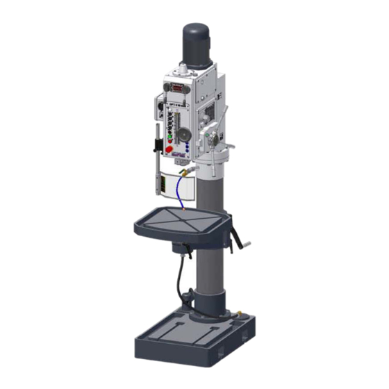
Page 18: Dimensions
OPTIMUM Technical data M A S C H I N E N - G E R M A N Y 2.11 Dimensions Fig.2-1: B50GSM Page 18 Geared drill B50 GSM Version 1.0.3 22 / 07 / 2014... -
Page 19: Assembly
Observe the rules for preventing accidents issued by your association for the prevention of occupational accidents and safety in the workplace or other inspection authorities. Hold the loads properly. Never walk under suspended loads! 22 / 07 / 2014 Version 1.0.3 B50 GSM Geared drill Page 19... -
Page 20: Storage
The substructure has to be prepared in a way that possibly used coolant cannot penetrate into the ground. Page 20 Geared drill B50 GSM Version 1.0.3 22 / 07 / 2014... -
Page 21: Assembly
Secure the lifting loop in the eye bolt on the drilling head „Operating material“ on page 17. 3.4.4 Installation Check the horizontal orientation of the base of the geared drill with a level. 22 / 07 / 2014 Version 1.0.3 B50 GSM Geared drill Page 21... -
Page 22: Securing
„Operating material“ on page 17. mounting slots(4) Fig. 3-2: Foot B50 GSM Fig. 3-3: Attachment to the base ATTENTION! Tighten the anchor bolt nuts in the geared drill until it is firmly secured and can neither move during operation nor be overturned. -
Page 23: First Use
Only use the clamping materials (e.g. drill chuck) which had been delivered together with the machine or as optional equipment offered by OPTIMUM. Use the working clamping materials only in the provided admissible speed range. Workpiece clamping materials must only be modified according to the recommendations of OPTIMUM or of the clamping material manufacturer. -
Page 24: Checks
M A S C H I N E N - G E R M A N Y Coolant pump Fig. 3-4: Coolant pump B50 GSM ATTENTION! The coolant pump also delivers if it turns into the wrong direction. The pump will become inoperable after a short time if it turns into wrong direction. -
Page 25: Handling
Gear selector for speed increments Control panel Spindle lever and switch spindle feed Drill chuck guard Drilling table Cooling pump Clamping lever for table rotation Fig.4-1: Geared drill B50 GSM 22 / 07 / 2014 Version 1.0.3 B50 GSM Geared drill Page 25... -
Page 26: Control Panel
The function of the micro switches in the drilling depth and the function of the direction of rota- tion change by the push-button actuators in the guide lever are activated. Page 26 Geared drill B50 GSM Version 1.0.3 22 / 07 / 2014... - Page 27 This operation control light on the control panel will illuminate when the main switch is on. Main switch Interrupts or connects the power supply. Gear selector Use the gear selectors to select the speed of the spindle. 22 / 07 / 2014 Version 1.0.3 B50 GSM Geared drill Page 27...
-
Page 28: Drill Depth Stop
Re-tighten the clamping screw for drill depth stop. The spindle can now only be lowered to the set depth. Spindle feed Spindle feed can be manual or automatic. Page 28 Geared drill B50 GSM Version 1.0.3 22 / 07 / 2014... -
Page 29: Manual Spindle Feed
Turn the selector switch to the position “0“. Turn the handwheel in order to turn the spindle. Set the required position with the handwheel. Handwheel spindle fine feed Selector switch Fig.4-7: Spindle fine feed 22 / 07 / 2014 Version 1.0.3 B50 GSM Geared drill Page 29... -
Page 30: Removing, Mounting Of Drill Chucks And Drill Bits
The tool and /or the drill chuck will fall down. Push the spindle lever upward. The tapered shank is pushed out of the sleeve. Fig.4-9: Removing Page 30 Geared drill B50 GSM Version 1.0.3 22 / 07 / 2014... -
Page 31: Mounting The Drill Chuck
The friction generated during rotation can cause the edge of the tool to become very hot. Cool the tool during drillings. This will give better results and make the tool last longer. Coolant charging hole Fig.4-12: Charging hole 22 / 07 / 2014 Version 1.0.3 B50 GSM Geared drill Page 31... -
Page 32: Working With The Machine
Danger of clothing and/or long hair getting caught. • Make sure to wear a well-fitting work during drilling work. • Do not use gloves. • If necessary, wear a hairnet. Page 32 Geared drill B50 GSM Version 1.0.3 22 / 07 / 2014... -
Page 33: Bit
Bit diameter Material Steel, alloyed, up to 600 N/ 5600 3550 2800 2240 2000 1600 1400 1250 1120 E 0,04 0,063 0,08 0,10 0,125 0,125 0,16 0,16 0,20 22 / 07 / 2014 Version 1.0.3 B50 GSM Geared drill Page 33... - Page 34 For rust-free materials (e.g. VA- or NIR steel sheets) do not work with a center punch as the material might harden and the drills will become quickly blunt. • The workpieces need to be clamped low inflexibly and stable (vice, screw clamp). Page 34 Geared drill B50 GSM Version 1.0.3 22 / 07 / 2014...
-
Page 35: Determining The Cutting Speed And The Speed
5308 6369 8493 10616 1092 1365 1638 1820 2275 2730 3185 3640 4550 5460 7279 9099 1194 1433 1592 1990 2389 2787 3185 3981 4777 6369 7962 22 / 07 / 2014 Version 1.0.3 B50 GSM Geared drill Page 35... - Page 36 1108 1385 24.0 1062 1327 25.0 1019 1274 26.0 1225 27.0 1180 28.0 1137 29.0 1098 30.0 1062 31.0 1027 32.0 33.0 34.0 35.0 36.0 37.0 38.0 Page 36 Geared drill B50 GSM Version 1.0.3 22 / 07 / 2014...
-
Page 37: Examples To Calculatory Determine The Required Speed For Your Drilling Machine
1st working step: Pre-drilling with Ø 5 mm (0.2"). 2nd working step: Pre-drilling with Ø 15 mm (0.6"). 3rd working step: Drilling with Ø 30 mm (1.2"). 22 / 07 / 2014 Version 1.0.3 B50 GSM Geared drill Page 37... -
Page 38: Maintenance
• long service life of the machine and • the quality of the products you manufacture. Installations and equipment of other manufacturers must also be in optimum condition. ENVIRONMENTAL PROTECTION During work on the drilling head, make sure that •... -
Page 39: Safety
„Safety check“ on page 12 WARNING! Before connecting the machine you must check that • there is no danger for the staff, • the machine is undamaged. 22 / 07 / 2014 Version 1.0.3 B50 GSM Geared drill Page 39... -
Page 40: Inspection And Maintenance
Oil fittings Fig.6-2: Oil fitting on the head every day Oil the greasing connections Oil fitting Fig.6-3: Lubricating nipple of sleeve and support of drilling machine table Page 40 Geared drill B50 GSM Version 1.0.3 22 / 07 / 2014... - Page 41 Turn the spring housing in direction "+" by one screw turn. Retighten the hexagon socket screws (3). as required Spring housing Hexagon socket screw(3) Setting direction Fig.6-4: Spring housing 22 / 07 / 2014 Version 1.0.3 B50 GSM Geared drill Page 41...
- Page 42 Fill in the open gear lubricating system of drill about 2.7 quarts of oil. Turn the gear drill. Check the oil level sight glass. The sight glass (oil removed) operation needs to be covered during the half. Page 42 Geared drill B50 GSM Version 1.0.3 22 / 07 / 2014...
- Page 43 Re-fill the gear with gear oil. Approx consumption. 2.7 quarts. Check the correct level of the oil. „Operating material“ on page 17. „Lubricant table“ on page 45 22 / 07 / 2014 Version 1.0.3 B50 GSM Geared drill Page 43...
- Page 44 (bayonet cap). Replace the light bulb. Screw the glass cover on the machine lighting again. as required Machine lighting Fig.6-10: Machine lighting Page 44 Geared drill B50 GSM Version 1.0.3 22 / 07 / 2014...
-
Page 45: Repair
Should technical assistance be required, contact LDS Industries at 1-630-785-6437. Optimum Maschinen - Germany and LDS Industries are not liable for, nor do they guarantee against, damage or operating malfunctions resulting from alteration, abuse, lack of main- tenance or this product’s use for other than its intended purpose. -
Page 46: Spare Parts - B50Gsm
OPTIMUM Spare parts - B50GSM M A S C H I N E N - G E R M A N Y Spare parts - B50GSM Spare parts drawing drilling head 22.7.14... -
Page 47: Spare Parts Drawing Drilling Head 1-7
OPTIMUM Spare parts - B50GSM M A S C H I N E N - G E R M A N Y Spare parts drawing drilling head 1-7 Parts drawing drilling head from year of construction 2008 22.7.14... -
Page 48: Spare Parts Drawing Drilling Head 2-7
OPTIMUM Spare parts - B50GSM M A S C H I N E N - G E R M A N Y Spare parts drawing drilling head 2-7 22.7.14... -
Page 49: Spare Parts Drawing Drilling Head 3-7
OPTIMUM Spare parts - B50GSM M A S C H I N E N - G E R M A N Y Spare parts drawing drilling head 3-7 22.7.14... -
Page 50: Spare Parts Drawing Drilling Head 4-7
OPTIMUM Spare parts - B50GSM M A S C H I N E N - G E R M A N Y Spare parts drawing drilling head 4-7 22.7.14... -
Page 51: Spare Parts Drawing Drilling Head 5-7
OPTIMUM Spare parts - B50GSM M A S C H I N E N - G E R M A N Y Spare parts drawing drilling head 5-7 22.7.14... -
Page 52: Spare Parts Drawing Drilling Head 6-7
OPTIMUM Spare parts - B50GSM M A S C H I N E N - G E R M A N Y Spare parts drawing drilling head 6-7 22.7.14... -
Page 53: Spare Parts Drawing Drilling Head 7-7
OPTIMUM Spare parts - B50GSM M A S C H I N E N - G E R M A N Y Spare parts drawing drilling head 7-7 22.7.14... -
Page 54: Spare Parts Drawing Column And Drilling Table 1-2
OPTIMUM Spare parts - B50GSM M A S C H I N E N - G E R M A N Y Spare parts drawing column and drilling table 1-2 22.7.14... -
Page 55: Spare Parts Drawing Column And Drilling Table 2-2 (Optional)
OPTIMUM Spare parts - B50GSM M A S C H I N E N - G E R M A N Y 7.10 Spare parts drawing column and drilling table 2-2 (optional) 22.7.14... -
Page 56: Drill Chuck Guard
OPTIMUM Spare parts - B50GSM M A S C H I N E N - G E R M A N Y 7.11 Drill Chuck Guard 22.7.14... -
Page 57: Wiring Diagram
OPTIMUM Spare parts - B50GSM M A S C H I N E N - G E R M A N Y 7.12 Wiring diagram 22.7.14... -
Page 58: Parts List
OPTIMUM Spare parts - B50GSM M A S C H I N E N - G E R M A N Y 7.13 Parts list Description Qty. Drawing no. Size Item no. GB5783-86 Socket head screw M12×30 GB97.1-86 Washer Socket head screw GB70-85 M8×25... - Page 59 OPTIMUM Spare parts - B50GSM M A S C H I N E N - G E R M A N Y Description Qty. Drawing no. Size Item no. Profile Key Z5050-03-123 0303450353 Spring Pin GB879-86 5×24 0303450354 Shaft Z5050-03-121...
- Page 60 OPTIMUM Spare parts - B50GSM M A S C H I N E N - G E R M A N Y Description Qty. Drawing no. Size Item no. Gear Z5050-03-67 Z=33 m=2 03034503124 Gear Z5050-03-68 Z=22 m=2 03034503125 Washer...
- Page 61 OPTIMUM Spare parts - B50GSM M A S C H I N E N - G E R M A N Y Description Qty. Drawing no. Size Item no. Worm gear Z5050-03-98 03034503194 Spacer Z5050-03-104 03034503195 Needle Bearing GB/T290-1998 HK4520...
- Page 62 OPTIMUM Spare parts - B50GSM M A S C H I N E N - G E R M A N Y Description Qty. Drawing no. Size Item no. Washer GB/T97.1 Thread rod GB/T898 M16×75 Plate Z5050-01-05 03034503259 Screw GB/T70 M6×20...
-
Page 63: Electrical Terminal Diagram
OPTIMUM Spare parts - B50GSM M A S C H I N E N - G E R M A N Y 7.14 Electrical terminal diagram 22.7.14... -
Page 64: Spare Parts Electrical Components
OPTIMUM Spare parts - B50GSM M A S C H I N E N - G E R M A N Y 7.14.1 Spare parts electrical components Item no. Pos. Description Specification Function Main switch LW8GS-25/0402 Main power On/Off 03034503SA0... -
Page 65: Troubleshooting
Replace • Excessive preloading of the • Reduce bearing slack for fixed heated bearing • Reduce bit speed/feed • Working at high rate for a long time 22 / 07 / 2014 Version 1.0.3 B50 GSM Geared drill Page 65... - Page 66 Adjust gib to the correct slack • Chuck loose using the adjusting screws • Tool dull • Check, re-tighten • Piece loose • Sharpen or replace tool • Secure the piece properly Page 66 Geared drill B50 GSM Version 1.0.3 22 / 07 / 2014...
-
Page 67: Appendix
Piece to be drilled or machined. Tool Bit, countersink, etc. Locking bolt Bolt for holding the drilling spindle at a given height for removing the chuck or tool. 22 / 07 / 2014 Version 1.0.3 B50 GSM Geared drill Page 67... -
Page 68: Limited Warranty
OPTIMUM assumes no obligations or liability on account of any unauthorized recommendations, opinions or advice as to the choice, installation or use of products. - Page 69 Table cutting speeds / infeed ....35 Technical data ......... 16 Drilling table ........16 Operating material ......17 Terminology/Glossary ......67 Troubleshooting ........65 User positions ......... 10 22 / 07 / 2014 Version 1.0.3 B50 GSM Geared drill Page 69...
- Page 70 OPTIMUM Index M A S C H I N E N - G E R M A N Y Page 70 Geared drill B50 GSM Version 1.0.3 22 / 07 / 2014...
Need help?
Do you have a question about the B50 GSM and is the answer not in the manual?
Questions and answers