Table of Contents

Related Manuals for Fluke Calibration 9500B


Summary of Contents for Fluke Calibration 9500B
- Page 1 9500B High Performance Oscilloscope Calibrator Calibration Manual November 2019 © 2019 Fluke Corporation. All rights reserved. Specifications subject to change without notice. All product names are trademarks of their respective companies.
- Page 2 LIMITED WARRANTY AND LIMITATION OF LIABILITY Each Fluke product is warranted to be free from defects in material and workmanship under normal use and service. The warranty period is one year and begins on the date of shipment. Parts, product repairs, and services are warranted for 90 days.
-
Page 3: Table Of Contents
Firmware Upgrade .................... 4 Introduction ....................4 Procedure ...................... 5 Active Heads ....................7 Model 9500B Test and Selftest ................7 Types of Tests ....................7 Test Mode ..................... 7 Base, Heads, All and Fast Selftest ..............8 Aborting the Selftest ..................9 Selftest Runs to Completion ................. - Page 4 Verifying the Edge Function ................65 Verifying the Load Capacitance Measurement Function (Ε) ......70 Calibration ......................74 9500B Mainframe Calibration and Active Head™ Calibration ......74 Mainframe Unit Calibration ................74 Active Head Calibration ..................75 Other Functions ....................75 Mainframe Unit Manual Calibration ..............
- Page 5 The Adjustment Screen ..................91 Setting Target Values..................91 Selecting Default Calibration Targets ............92 Modifying a Calibration Target ..............92 Calibrating the Model 9500B at Target Values ..........93 Adjust Output Amplitude ................93 Target Selection .................... 94 'RESET CAL POINT' ................... 95 Standard Calibration of AC Functions ..............
- Page 6 9500B Calibration Manual Load Resistance Measurement Calibration ............115 9510/9530/9550/9560 Head Calibration Procedures ..........118 Levelled Sine Function: LF Gain ..............118 Levelled Sine Function: HF Calibration ............120 Calibrating the Edge Function ................128 Calibrating the Timing Markers (9510 only) ............ 140 Load Capacitance Function Calibration (9510 and 9530 only) ......
-
Page 7: Introduction
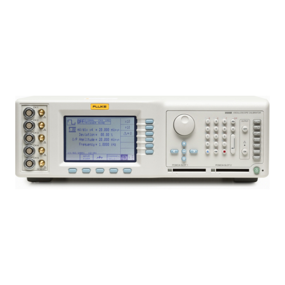
Introduction The Model 9500B is a state-of-the-art calibrator offering oscilloscope test and calibration capabilities from a single source, providing wide functionality (shown in Figure 1). (Variant 9500B/1100 is described—for other variants, refer to the 9500B Extended Specifations. See Specifications.) Erw001 Figure 1. -
Page 8: Safety Information
9500B Operators Manual • 9500B Users Guide • Specifications Safety Specifications are located in the Safety Specifications section of the 9500B Safety Sheet. Complete specifications are at www.flukecal.com. See the 9500B Extended Specifications. Routine Maintenance General Cleaning W Warning To prevent fire, explosion, or personal injury, disconnect the power line cord before cleaning. -
Page 9: Removing The Top Cover
Removal of the guard shield will compromise the traceable calibration of the instrument, and a full recalibration of the 9500B will be required. If removal of the guard shield is authorized, take care to heed the WARNING printed on it next to the XW symbols. -
Page 10: Refitting The Filter Element
Interface Adaptor' (PC-Card). To do this, the Model 9500B has been fitted with FLASH memory chips to provide the update capability. If an upgrade is required for your Model 9500B unit(s), your Service Center will inform you and provide the appropriate PC-Card. -
Page 11: Procedure
PRINT option to obtain a hard copy of the results. 2. Prepare the 9500B: a. Switch 9500B Power OFF. b. Locate the FACTORY SET switches on the 9500B rear panel: erw162 1) Remove the switch cover by releasing its retaining screw. - Page 12 On the right of the 9500B front panel, press the Mode key. At the bottom of the 9500B LCD display, press the soft CONFIG key, and check that the firmware issue, shown on the screen, matches that on the PC- Card.
-
Page 13: Active Heads
Model 9500B Test and Selftest Active Heads A range of Active Heads are available for the 9500B Oscilloscope calibrator. Active head connector wear can seriously impact product specifications. Fluke Calibration recommends that connectors are inspected for wear or damage before use. The recommended interval for connector replacement based on average use is every two years, and once per year for Active heads with higher than average use. -
Page 14: Base, Heads, All And Fast Selftest
BASE, HEADS, ALL and FAST selftests follow the same format. By pressing one of these four screen keys on the 'Select test' menu screen, the 9500B runs that selftest. The first screen shows the type of test, the pathway under test and the number of tests remaining. -
Page 15: Aborting The Selftest
High Performance Oscilloscope Calibrator Model 9500B Test and Selftest erw169 (In the following descriptions, it is assumed that a BASE selftest was selected. Other selftests have the selftest name appearing on the screen). Aborting the Selftest ABORT: Stops the selftest and displays the appropriate 'ABORTED' screen. -
Page 16: Selftest Runs To Completion
If the selftest is not aborted, it will run to completion, and if the test is successful with no failures, a screen will appear: erw172 If failures were encountered during the test, the 9500B will display a completion screen. For example: erw173... -
Page 17: Viewing The Test Results
Note If the cause of failure is not immediately obvious, and it is intended to consult your Fluke Calibration Service Center, please ensure that you either: copy the details from the screen for all the reported failures, or: print out the results. -
Page 18: Printing The Test Results
In this case, immediately switch Power Off and report the fault to your Service Center. The first normal action at power on is to show the Fluke Calibration logo and Product name, and then the 9500B will run a fast selftes. -
Page 19: Interface Test
Model 9500B Test and Selftest Interface Test The interface test selectively checks the 9500B front panel operations, covering display memory integrity, keyboard operation, the display itself, integrity and formatting of static RAM memory cards for Procedure mode, the correct operation of a connected tracker ball, and the correct operation of a connected printer. -
Page 20: Display Memory Checks
9500B Calibration Manual Display Memory Checks Pressing the DISPLAY MEMORY key on the 'Select test' menu screen transfers to the 'Memory test.' screen, and the sequence of tests begins. The test in progress is reported on the screen: erw180 erw181 The other tests reported are: •... -
Page 21: Keyboard Checks
If a failure is reported, rectification will require access to the internal circuitry, so no further user action is recommended, except to report the result to your Fluke Calibration Service Center. EXIT returns to the Interface 'Select test' menu screen. -
Page 22: Display Checks
Rectification will require access to the internal circuitry, so no further user action is recommended, except to report the result to your Fluke Calibration Service Center. EXIT returns to the Interface 'Select test' menu screen. -
Page 23: Memory Card Checks
Rectification will require access to the internal circuitry, so no further user action is recommended, except to report the result to your Fluke Calibration Service Center. - Page 24 Results card. The 9500B first checks for the presence of the correct SRAM card. If there is no card in the slot, if the card in the slot is not a SRAM card, or if it is a SRAM card but not write-...
- Page 25 For a re-chargeable card with a low battery, the low/dead message may take several minutes to clear after pressing OK. The next test is to check the size of the card memory. While the 9500B is checking, it will place the following message on the screen:...
- Page 26 9500B Calibration Manual Once the size check is completed, the 9500B starts on a 'read/write' check; meanwhile the display changes to: erw193 After the read/write check, the 9500B starts on a 'walking ones' check, and the message on the display changes to: Performing WALKING ONES test.
-
Page 27: Tracker Ball Checks
This should narrow the fault down to one slot or one card. If it is suspected that the 9500B is at fault, it is wise to report the result to your Fluke Calibration Service Center. -
Page 28: Printer Checks
The possible responses are shown on the diagram. Note that the center key on the tracker has no function in its operation with the 9500B, and is not tested, so pressing this key should have no effect, unless the tracker is defective. -
Page 29: Printing Selftest Results
It is possible to diagnose the defect source by checking a second printer unit on the same 9500B, or the same printer unit on a different 9500B. Rectification may require access to the internal circuitry of the 9500B or printer unit, so no further user action is recommended, except for obvious setup errors. -
Page 30: Printing Setup
Printer is in online state, or connected AUTO_FEED_L Output Paper is automatically fed 1 line after printing. This line is fixed _H (high) by the 9500B to disable autofeed ERROR_L Input Printer is in 'Paper End', 'Offline' or 'Error' state... -
Page 31: Data Formatting
High Performance Oscilloscope Calibrator Error Reporting Subsystem Data Formatting The required printout style, format and data is pre-determined depending on whether Base, Heads, All and Fast test results are being printed, and on the type of printer to be used. It is necessary to enable a particular printer type via Configuration mode, only if the format for that printer is required. -
Page 32: Error Messages
9500B Calibration Manual Error Messages System Trip Errors For all system trip errors, the error condition is reported only via the front panel. The error will pull the processor reset line to restart the system as at power-on. The screen will display a message indicating that there has been a system trip error and thus the processor has been reset. -
Page 33: Command Errors (Cme)
Error Queue. Command Error Reporting The error is reported by the mechanisms that deal with status reporting. The Command Errors implemented in the 9500B are listed below; their error numbers conform to those defined in the SCPI Standard document: -100,"Command error"... -
Page 34: Execution Errors (Exe)
The QYE bit (2) is set true in the Standard-defined Event Status Byte, and the error code number is appended to the Error queue. The error is reported by the mechanisms described in the 9500B Users Guide, Retrieval of Device Status Information section, which deals with status reporting. -
Page 35: Device-Dependent Errors (Dde)
High Performance Oscilloscope Calibrator Error Messages Device-Dependent Errors (DDE) A Device-Dependent Error is generated if the device detects an internal operating fault (eg. during self-test). The DDE bit (3) is set true in the Standard-defined Event Status Byte, and the error code number is appended to the Error queue. The error description appears on the display, remaining visible until the next key press or remote command. -
Page 36: Device-Dependent Errors Reported Only Remotely Via The Ieee-488 Interface
9500B Calibration Manual -9022, “Only a restricted setting available” -9023, “Maximum frequency for this waveform is 1.11MHz” -9024, “Minimum highlight period is 20ns” -9025, “No further display ranges available” -9026, “No further options” -9027, “Current probe accessory must be fitted to active head”... -
Page 37: Device-Dependent Errors Reported Both Locally And Remotely
High Performance Oscilloscope Calibrator Error Messages Device-Dependent Errors Reported both Locally and Remotely Errors are reported both on the front panel screen and via the IEEE-488 interface. Note that the locally-presented error message will not include the error number. General 1001, “Active head removed with output on”... - Page 38 1062, "9560 head required for 70ps edge" 1063, "Calibration of this function not allowed with a 9560" 1064, "Multi-channel DC cannot mix 9560 with other head types" 1065, "Pulse Width characterisation requires 9500B hardware" 5010, “Priority OFF received” 5011, “Gain request limited”...
- Page 39 High Performance Oscilloscope Calibrator Error Messages Calibration 4001, “Corrupt calibration store, using default” 4002, “NVRAM Failed to save configuration” 4003, “Password incorrect” 4004, “Calibration switch not enabled” 4005, “Password incorrect” 4007, “Amplitude outside limits” 4008, “Calibration is password protected” 4009, “Frequency outside limits” 4010, “Invalid calibration function”...
- Page 40 9500B Calibration Manual 4220, "WARNING: Previous cal outside limits - using defaults" 4221, "WARNING: Cal data not stored: Exit again to abandon data" Characterization 4501, "Limits: main DAC gain" 4502, "Limits: composite DAC zero" 4503, "Limits: trim DAC gain" 4504, "Limits: offset DAC gain"...
- Page 41 High Performance Oscilloscope Calibrator Error Messages Configuration 4002, "Failed to save configuration" -7003, "Day entry is not a valid number" -7004, "Day separator is incorrect" -7005, "Month entry is not a valid number" -7006, "Month separator is incorrect" -7007, "Century entry is not a valid number" -7008, "Year entry is not a valid number"...
-
Page 42: Verification
Verification on Receipt from the Factory Each 9500B is dispatched from the factory with a Certificate of Calibration, which gives detailed results of its pre-shipment performance. However, organizations may wish to confirm that all instruments perform within published specifications, on receipt from their manufacturers. -
Page 43: Interconnections
For each chosen verification point it will be necessary to know absolute measurement limits which can be used to judge whether or not the 9500B is performing within its specification. As mentioned earlier, the accuracy specifications detailed in the 9500B... -
Page 44: Verifying The Dc/Square Function: Dc Voltage
9500B Calibration Manual The list of topics above are placed in the order in which the 9500B Mainframe functions should be verified. Although it is not essential to verify all the functions at any one time, functions higher in the list should be verified before those lower in the list. - Page 45 High Performance Oscilloscope Calibrator 9500B Mainframe Verification by Functions Verification Setup 1. Connections: Ensure that the 9500B is connected to the DMM as shown in Figure 3, or via a similar BNC-4mm adaptor, and that both instruments are powered on and warmed up.
- Page 46 9500B Calibration Manual Note Please copy the following table. Enter the measurements in the Measured Value column on the copy. Table 2. DC/Square DC (+) Verification into 1 Ω Load Verif. Point Absolute Limits (+DCV) Output Voltage Measured Value Lower...
- Page 47 High Performance Oscilloscope Calibrator 9500B Mainframe Verification by Functions Note Please copy the following table. Enter the measurements in the Measured Value column on the copy. Table 3. DC/Square DC (-) Verification into 1 Ω Load Verif. Point Absolute Limits (-DCV)
-
Page 48: Verifying The Dc/Square Function: Square Voltage
Verification Setup, at the verification points shown in Tables 3, 4 and Equipment Requirements • The UUT Model 9500B Mainframe, with 9510 or 9530 Active Head. • A high resolution Standards DMM with RMS AC Voltage accuracy of ±0.01 % or better, from 2.5 mV to 35 V, at 1 kHz. - Page 49 High Performance Oscilloscope Calibrator 9500B Mainframe Verification by Functions erw202 Figure 4. DC/Square; Square Voltage Verification — Interconnections Verification Procedure Copy the three tables: 4, 5 and 6. Follow the correct sequence of verification points as shown on the tables, and carry out the following operations at each verification point.
- Page 50 Table. c. Check that the Measured Value is at or between the Absolute Limits. 7. 9500B: Set Output OFF. 8. Press the WAVEFORM soft key. Select Square (negative) by pressing the key on the right of the screen. Repeat steps (2) to (7), but using Table 5 for each of the verification points.
-
Page 51: Verifying The Lf Sine Voltage Function
High Performance Oscilloscope Calibrator 9500B Mainframe Verification by Functions Table 5. DC/Square Square (-) Verification at 1 kHz into 1 MΩ Load Absolute Limits Absolute Limits Measured Verif. Output Output (pk-pk) (RMS) Value Point Frequency Voltage Voltage (RMS) (pk-pk) (RMS) - Page 52 Calibration Manual Equipment Requirements • The UUT Model 9500B Mainframe, with 9510 or 9530 Active Head. • A high resolution Standards DMM with RMS AC Voltage accuracy of ±0.3 % or better, between 0.5 V and 2 V, at 1 kHz and 45 kHz. Example: Model 1281 Digital Multimeter.
- Page 53 High Performance Oscilloscope Calibrator 9500B Mainframe Verification by Functions Verification Procedure 1. Verification Points: Refer to Table 4. 2. DMM: Select the correct RMS Voltage range for the verification point RMS Output Voltage. 3. 9500B: Set the Output Volts p-p as required for the verification point.
-
Page 54: Verifying The Time Markers Function
Verification Procedure, at the verification points shown in Table 8. Equipment Requirements • The UUT Model 9500B Mainframe, with 9510 or 9530 Active Head. • Digital counter for 0.25 ppm clock accuracy measurements. Example: Hewlett Packard Model HP53131A with Option 012. - Page 55 2. Counter: Select the required function to measure period. 3. 9500B: a. Ensure that the 9500B is in MANUAL mode and then select the Time Markers function (ζ key). b. Use the bottom soft key on the right of the screen, highlighting 1/f (Γ), to view output Period on the...
-
Page 56: Verifying The Load Resistance Measurement Function
Table 9. Equipment Requirements • The UUT Model 9500B with 9510 or 9530 Active Head. • A traceable, high-resolution Standards DMM, used to measure resistance at 1 MΩ and 50 Ω, with an accuracy of 0.02 % or better. For example, a Model 1281 Digital Multimeter. - Page 57 Set the Model 4955 Calibration Adaptor switch as shown in Table 9. 4. If not using the Model 4955, set up external circuitry to measure the appropriate load resistor (4-wire connection), with the 9500B Active Head output BNC disconnected.
- Page 58 9500B Active Head output BNC. 9. Press the ON key to turn the 9500B output on. 10. Using the 9500B, take a Resistance measurement and note the result (R meas) in Table 9. 11. 9500B: Set OUTPUT OFF.
-
Page 59: Verifying The Pulse Width Function
Verification Procedure, at the verification points shown in Table 10. Equipment Requirements • The UUT Model 9500B Mainframe, with 9510 or 9530 Active Head. • Digital counter for 0.25 ppm clock accuracy measurements. Example: Hewlett Packard Model HP53131A with Option 012. -
Page 60: 9510/9530/9550/9560 Head Verification By Functions
• Load Capacitance Measurement Function The list of topics above are placed in the order in which the 9500B Head functions should be verified. Although it is not essential to verify all the functions at any one time, functions higher in the list should be verified before those lower in the list. Head verification involves the use of a verified 9500B Mainframe. -
Page 61: Verifying The Leveled Sine Function: Lf Gain
Verification Procedure, at the verification points shown in Table 11. Equipment Requirements • The UUT Active Head, connected to a verified Model 9500B Mainframe (refer to Verifying the LF Sine Voltage Function). • A high resolution Standards DMM with RMS ACVoltage accuracy of 0.3 % or better, from 10 mV to 1.5 V, at 1 kHz, 45 kHz and 50 kHz. - Page 62 9500B Calibration Manual Verification Setup 1. Connections: Ensure that the 9500B is connected to the DMM as shown in Figure 9, or via a similar PC3.5 or BNC-4 mm adaptor, and that both instruments are powered on and warmed up.
- Page 63 For SGN1-6 check that the Calculated Value is at or between the RMS Limits. e. For SGN7-11 check that the Measured Value is at or between the RMS Limits. 7. 9500B: Set Output OFF. Table 11. Sine Verification into 50 Ω Load Verif.
-
Page 64: Verifying The Leveled Sine Function: Flatness
600 MHz. Equipment Requirements • The UUT Active Head, connected to a verified Model 9500B Mainframe (for Mainframe verification, refer to Verifying the LF Sine Voltage Function). • RF Power Meter for Power measurements from 50 kHz and 6.4 GHz and from 100 mVp-p to 3 Vp-p into 50 Ω. - Page 65 Record the result in the 'Measured p-p Voltage at 50 kHz' column on the copy of the Table. 6. Flatness: a. Set the 9500B Frequency to the first 'SF' point in the table. b. measure the 9500B output power and calculate the Pk-Pk value of 9500B output voltage into 50 Ω:...
- Page 66 But this is a power uncertainty, and the pk-pk voltage uncertainty will be half: ±0.7 %. • With this we must combine (by RSS Method) the 9500B pk-pk voltage flatness specification. At 10 MHz, the 9500B specification relative to 50 kHz is ±2.0 %.
- Page 67 2. For each of the verification points: Combine the Total Measurement Uncertainty and the 9500B Sine function accuracy, using the RSS method, to calculate the Flatness Acceptance Limits. For further assistance, refer to Calculation of Acceptance Limits.
- Page 68 2.5 GHz ±4.0 SF25†† 3 GHz ±4.0 SF60††† 4 GHz ±4.0 SF61††† 5 GHz ±4.0 SF62††† 5.5 GHz ±4.0 SF63††† 6 GHz ±4.0 †: Additional verification points for: 9500B/1100 and 9500B/3200 (†); 9500B/3200 only ††) and 9500B/3200 with 9560 (†††).
- Page 69 SF37 2.5 GHz ±4.0 SF38 3 GHz ±4.0 SF64 4 GHz ±4.0 SF65††† 5 GHz ±4.0 SF66††† 5.5 GHz ±4.0 SF67††† 6 GHz ±4.0 Additional verification points for: 9500B/1100 and 9500B/3200 (†); 9500B/3200 only (††) and 9500B/3200 with 9560 (†††).
- Page 70 SF50†† 2.5 GHz ±4.0 SF51†† 3 GHz ±4.0 SF68††† 4 GHz ±4.0 SF69††† 5 GHz ±4.0 SF70††† 5.5 GHz ±4.0 SF71††† 6 GHz ±4.0 Additional verification points for: 9500B/1100 and 9500B/3200 (†); 9500B/3200 only (††) and 9500B/3200 with 9560 (†††).
-
Page 71: Verifying The Edge Function
Verification Setup and Verification Measurement Procedure, at the verification points shown in Table 16. Equipment Requirements • The UUT Active Head, connected to a verified Model 9500B Mainframe. • High-bandwidth sampling oscilloscope with bandwidth ≥6 GHz for Risetime measurements. - Page 72 Use of an attenuator is typically required for outputs above 1 V pk-pk. 3. 9500B: Ensure that the 9500B is in MANUAL mode and then select the Edge function (Ι key). Select the required output Signal Channel (50 Ω Load), Trigger Channel, Cable...
- Page 73 Edge Function Rise/fall time = ObservedRi seTime ScopePulse sponseTime − c. Record the Measured Edge function rise/fall time on the copy of the Table. d. Record the 9500B displayed Rise Time on the copy of the Table. 8. 9500B: Set Output OFF.
- Page 74 Uncertainty (500 ps at 25mV), is: ±20 ps. • With this we must combine (by RSS Method) the 9500B Speed specification. At 500 ps, the 9500B specification speed is +50 ps to -150 ps. • Considering the upper limit: Acceptance Limit = = 53.85 ps...
- Page 75 Please copy the following table. Enter the calculation results and measurements in the appropriate columns on the copy. Table 16. Edge Function Verification — Rise/Fall Time at 1 MHz (Period 1 μs) into 50 Ω Load Nominal 9500B Output Rise/Fall Lower Upper User’s Total...
-
Page 76: Verifying The Load Capacitance Measurement Function (Ε)
*: Verification points EDG11 to EDG20 available for Active Head Model 9530 only. †: 9500B displayed value accuracy specification: for γs , ±40 ps; for η , ±15 ps; for ι, ±11 ps; for ϕ, ±4 ps. **: Verification points EDG21 to EDG28 available for Active Head Model 9560 only. - Page 77 High Performance Oscilloscope Calibrator 9510/9530/9550/9560 Head Verification by Functions Equipment Requirements • The UUT Active Head, connected to a verified Model 9500B Mainframe. • Two Calibrated Capacitance Units (BNC-terminated): o Calibrated value between 15 pF and 25 pF o Calibrated value between 85 pF and 95 pF Suitable capacitance values can be constructed from a length of coaxial cable fitted with a BNC connector at one end and open circuit at the other.
- Page 78 ±[(2 % x 20 pF) + 0.25 pF] = ±[0.4 pF + 0.25 pF] = 0.65 pF We must now subtract this value from 20pF for the lower limit (19.35 pF), and add it to 20 pF for the higher limit (20.65 pF). 3. Enter the 9500B Absolute Limits into their respective columns on Table 17.
- Page 79 Set Output ON and wait for the Load Capacitance reading to settle. 4. Reading: a. Record the 9500B reading in the Measured Value column of the copy of the Table. b. Check that the Measured Value is at or between the Absolute Limits.
-
Page 80: Calibration
9500B Calibration Manual Calibration This section outlines general procedures for calibrating the Model 9500B. In it you will find the recommended calibration methods, details of the parameters that require calibration and the procedures needed to calibrate them. This section is divided into the following sub-sections: •... -
Page 81: Active Head Calibration
Auxiliary Input • Input Leakage Attempting to select these functions during Mainframe calibration, (or those in Active Head Calibration) while the Model 9500B is in CAL mode, will result in an error message being displayed: No calibration for this function... -
Page 82: Mainframe Unit Manual Calibration
3. Front Panel Base Calibration by Functions section details front panel operation to calibrate functions, providing connection diagrams and sequenced procedures. The Model 9500B Calibration Mode This section is a guide to the use of the Model 9500B's Calibration Mode, for manual calibration of the 9500B Mainframe. •... -
Page 83: Mode Selection
Overview of Calibration Operations Mode Selection 'Mode' Key Selection of any one of the Model 9500B's five operating 'Modes' is enabled by pressing the 'Mode' key at the bottom right of the 'CALIBRATION SYSTEM' key panel. erw211 This results in display of the mode selection screen:... -
Page 84: Mode Selection' Screen
2. A valid password must have been entered via the front panel keypad. Calibration Enable Switch The Calibration Enable DIP-switch is accessible, using a small screwdriver, through a recess on the Model 9500B's rear panel. erw213 DISABLE With the Calibration Enable switch in the 'DISABLE' position, any attempt to select Calibration mode by pressing the 'CALIB' screen softkey will result in the screen prompt "Calibration switch not enabled!"... -
Page 85: Password
Before the Calibration mode menu screen can be displayed you must now enter a valid password using the Model 9500B's alpha-numeric keyboard. For information about the initial 'shipment' password, and about the method of changing this to a custom password, refer to Passwords and Access in the 9500B Users Guide. -
Page 86: Calibration Mode Screen Softkeys
Accesses the Special Calibration menu so that you can perform several 'Chse' (Characterize) calibration operations, which must be done immediately before carrying out routine recalibration of the Model 9500B. FACTORY USE ONLY Accesses 'factory-set' calibration operations which can only be entered by a special password. -
Page 87: When To Characterize
The Characterize operations comprise sets of fully automatic internal adjustments, such as (in the case of Chse - DAC) checking and calibrating the linearity of the 9500B D-A converter, which is used to set the amplitude of its analog output functions. -
Page 88: Special Cal: 'Adjust Freq
This is really a calibration of the internal frequency source, to an external frequency standard. The 9500B generates a stream of square timing markers (as in Time Markers Function — refer to the 9500B Users Guide, Time Markers Function section) at 100 MHz. -
Page 89: Interconnections
The Model 9500B Calibration Mode Interconnections 9500B and Counter Setup 1. Connections: Connect the 9500B to the Counter and ensure that both instruments are powered ON and warmed up. Any model number head may be used (except 9550). 2. Counter: Select the required function to measure frequency. -
Page 90: Mainframe Standard Calibration (Base Cal)
9500B Calibration Manual Mainframe Standard Calibration (BASE CAL) Function Selection Pressing the 'BASE CAL' screen softkey displays a DC/Square'DC CAL' function screen (the 'Target Selection' screen) shown below, which appears on entry to Standard Calibration. erw219 Other available Mainframe calibrations are: •... -
Page 91: Cal Mode Function Screens
Generally, two special screens are provided to adjust each of the functions' calibration points. In CAL mode, the purpose of these screens is to allow you to set the 9500B into the various hardware configurations (also known as 'Cal Ranges') required during calibration, and initiate the necessary sequences of operations. -
Page 92: Hardware Configurations
Calibration Manual ‘Hardware Configurations' Although all functions in the 9500B appear to the operator to have a single continuous range which covers the entire span of output values from the lowest to the highest (for example, for DC Voltage from 888.00 μV to 222.4 V), internal devices such as voltage dividers and power amplifiers must be switched to achieve this total span. - Page 93 High Performance Oscilloscope Calibrator The Model 9500B Calibration Mode erw223 Figure 13. Access to Functions in Calibration Mode...
-
Page 94: Standard Calibration - Basic Sequences
9500B Calibration Manual Standard Calibration — Basic Sequences This section describes in more detail the main processes involved when calibrating each of the Model 9500B's 'hardware configurations' from the instrument's front panel. • Introduction o Aim of Calibration o General Calibration Process •... -
Page 95: Aim Of Calibration
The aim of calibrating the Model 9500B Oscilloscope calibrator is to determine the accuracy of its outputs, and if necessary adjust them so that they are within specification. If this calibration is to be traceable, then the 9500B's outputs must be compared with Traceable calibration standards of suitable 'Test Uncertainty Ratio'. -
Page 96: Waveform Selection
Connection of the Mainframe to the standards equipment must be routed through a signal channel head, with a trigger channel/cable if necessary. Signal Channel selection, Trigger Channel selection, Cable selection and Trigger Ratio operate in the same way as in normal DC/Square function. Refer to 9500B Users Guide, Menu Selections. -
Page 97: Retained Channel Memory
'Adjustment' screen — similar to the following: erw225 This screen initially shows the value to which the 9500B output is presently set, and the value of the selected target amplitude (whether 'default' or 'saved'). Note that on these values, triangular cursors indicate which digit will change when using the cursor keys or spinwheel. -
Page 98: Selecting Default Calibration Targets
• If you decide to use default values, rather than the values at which your 9500B was previously calibrated (assuming that the 'saved' and 'default' values are different), simply press the DEFAULT TARGETS softkey on the Target Selection screen. -
Page 99: Calibrating The Model 9500B At Target Values
• Returning to the Adjustment screen by pressing the same target soft key, it can be seen that the 9500B O/P Amplitude has also changed to the saved value in preparation for adjustment. Calibrating the Model 9500B at Target Values... -
Page 100: Target Selection
To prevent accidental calibrations due to inadvertent use of the CALIB key, initial use of the Adjustment screen takes place with the 9500B output OFF. If you accidentally press the ACCEPT CALIB key, or attempt a... -
Page 101: Reset Cal Point
Introduction, Target Selection Screen — Selecting Hardware Configurations, The Adjustment Screen and Calibrating the Model 9500B at Target Values of this section except that the frequency of the target calibration points must also be set. -
Page 102: Exit From Base Calibration - Cal Date And Cal Due Date
'exit' process. The normal means of exit from Calibration mode is to press the Mode key on the right of the front panel. When you do this, the 9500B will present a Warning screen to indicate that the 9500B calibration may have changed, and to offer you the following options: •... -
Page 103: Exit: Mode Key - Warning Screen
High Performance Oscilloscope Calibrator Standard Calibration — Basic Sequences Exit: Mode Key — Warning Screen To exit from Calibration, press the Mode key on the right of the front panel. The 9500B will present a 'Warning' display on the screen: erw229... -
Page 104: Setting The Cal Due Date And Advance Warning Period
If these parameters are not altered, then those which are already stored will be presented on any directly-printed certificate. To alter the CAL DUE date, press the CAL DUE DATE key. The 9500B will present the CAL DUE DATE screen: erw231 This screen also displays a stored CAL DATE reminder for calculating the cal due date. -
Page 105: Front Panel Base Calibration By Functions
Front Panel Base Calibration by Functions Introduction This section is a guide to the process of calibrating the Model 9500B's functions from the front panel. Other Functions No calibration is required for the following functions, as they are either calibrated for life... -
Page 106: Summary Of Calibration Process
General Procedure The Model 9500B Calibration Mode and Standard Calibration — Basic Sequences sections introduced the general calibration process for the Model 9500B. They also outlined the methods used to select functions, hardware configurations and target calibration points, and how to calibrate the 9500B at these target points. - Page 107 Target Selection screen. Any channel may be used for mainframe calibration. 17. Select the required 9500B hardware configuration by choosing the appropriate Cal Range. (Details of each function's hardware configurations and suitable output values to select them can be found in the detailed procedures provided later in this section).
-
Page 108: Sequencing Calibrations
26. Repeat steps (16) to (24) for each of the Cal Ranges associated with the 9500B function that is being calibrated. 27. Repeat steps (14) to (25) for each function of the 9500B which is to be calibrated. 28. Press the Mode key to exit from Calibration mode (refer to section Standard Calibration —... -
Page 109: Dc/Square - Dc Voltage Calibration
DC/Square: Square Voltage (Symmetrical) LF Sine Load Resistance Measurement DC/Square — DC Voltage Calibration Introduction This section is a guide to calibrating the Model 9500B's DC/Square Function, DC Voltage; using its front panel controls. • Calibration Equipment Requirements • Interconnections •... - Page 110 Figure 14, or via a similar BNC-4 mm adaptor, and that both instruments are powered on and warmed up. 9500B: Ensure that the 9500B is in BASE CAL mode and then select the DC/Square; DC Voltage (Positive) function (default selection when entering STD CAL). Select the required output Signal Channel (1 MΩ...
- Page 111 8. Press the ON key to turn the 9500B output on. 9. Press the TAB Δ key to return the cursor to the 9500B O/P Amplitude display, and increment or decrement this value using the cursor controls and/or spinwheel until the reading on the Standards DMM is the same as the displayed Target Amplitude value.
- Page 112 9500B Calibration Manual Table 19. DC/Square; DC Voltage (Positive) Hardware Configurations and Calibration Targets Target 1 (low) Target 2 (high) Function/ Hardware Configuration Waveshape Range Span Default Minimum Maximum Default Minimum Maximum 888.00 μV - 2.10 mV +1.0000 mV +0.9300 mV +1.0700 mV +1.9000 mV +1.7670 mV...
-
Page 113: Dc/Square - Square Calibration
High Performance Oscilloscope Calibrator Front Panel Base Calibration by Functions DC/Square — Square Calibration Introduction This section is a guide to calibrating the Model 9500B's DC/Square Function, Square Waveform; using its front panel controls. The following topics are covered: • Calibration Equipment Requirements •... - Page 114 Figure 15, or via a similar BNC-4 mm adaptor, and that both instruments are powered on and warmed up. 2. 9500B: Ensure that the 9500B is in BASE CAL mode and then select the DC/Square; Square Waveform (Positive) function (From entry default, in the Target Selection screen, press the WAVEFORM soft key and then press the 2 soft key on the right of the screen).
- Page 115 Square Wave and the resultant fall in its RMS value. 9. Press the ON key to turn the 9500B output on. 10. Press the TAB Δ key to return the cursor to the 9500B O/P Amplitude display, and increment or decrement this value using the cursor controls and/or spinwheel until the reading on the Standards DMM is the RMS equivalent of the displayed Target Amplitude pk-pk value calculated in operation (8).
- Page 116 9500B Calibration Manual Table 21. DC/Square; Square Waveform (Positive) Hardware Configurations and Calibration Targets Frequency Target Hardware Target 1 (low) pk-pk Target 2 (high) pk-pk Function/ Configuration Waveshape Range Default Minimum Maximum Default Minimum Maximum Default Minimum Maximum Span 1 kHz 0.9500 kHz...
-
Page 117: Lf Sine Voltage Calibration
64.200 V 190.00V 176.70 V 203.30 V LF Sine Voltage Calibration Introduction This section is a guide to calibrating the Model 9500B's LF Sine Function; using its front panel controls. The following topics are covered: • Calibration Equipment Requirements •... - Page 118 Target Selection screen. Calibration Procedure 1. Starting at Cal Range 1, calibrate at all calibration points listed in Table 21 by performing operations (2) to (13) below. 2. Select the required 9500B hardware configuration by choosing the appropriate Cal Range.
- Page 119 9. Press the ON key to turn the 9500B output on. 10. Press the TAB Δ key to return the cursor to the 9500B O/P Amplitude display, and increment or decrement this value using the cursor controls and/or spinwheel until the reading on the Standards DMM is the RMS equivalent of the displayed Target Amplitude pk-pk value calculated in operation (8).
- Page 120 Amplitude value will change to the Target Amplitude value, and the adjustment of the output amplitude at this target is complete. 12. Press the EXIT key to turn the 9500B output off and return to the Target Selection screen. 13. Repeat steps (3) to (12) for each of the target values displayed in the Target Selection screen.
-
Page 121: Load Resistance Measurement Calibration
High Performance Oscilloscope Calibrator Front Panel Base Calibration by Functions Load Resistance Measurement Calibration Introduction This section is a guide to calibrating the Model 9500B's Load Resistance Measurement Function; using its front panel controls. The following topics are covered: • Calibration Equipment Requirements •... - Page 122 50 Ω load, and that both instruments are powered on and warmed up. 2. 9500B: Ensure that the 9500B is in BASE CAL mode and then select the Load Resistance Measurement function (From entry default, in the Target Selection screen, press the Aux key on the right of the Front Panel).
- Page 123 13. Press the SAVE TARGET soft key. 14. Press the EXIT key to turn the 9500B output off and return to the Target Selection screen. 15. Repeat steps (2) to (14) for each of the target values displayed on the Target Selection screen (also see Table 25 below).
-
Page 124: 9510/9530/9550/9560 Head Calibration Procedures
50 Ω/1 MΩ Ratio Calibration • Exit from Head Calibration The list of topics above are placed in the order in which the 9500B Head functions should be calibrated. Head calibration requires the use of a verified 9500B Mainframe. Note Heads can be calibrated only within the bandwidth of the mainframe (see Table 26) e.g. - Page 125 DMM. Calibration Setup Connections: Ensure that the 9500B is connected to the DMM as shown in Figure 18, or via a similar BNC or PC3.5 to 4 mm adaptor, and that both instruments are powered on and warmed up.
-
Page 126: Levelled Sine Function: Hf Calibration
9500B Calibration Manual Calibration Procedure: LF Gain 1. Ensure that the 9500B is in HEAD CAL mode, then select Sine, Lo Frq Sine function. 2. Select TARGET 1. 3. Set output ON and wait for DMM reading to settle. 4. If using the Model 4955 Calibration Adapter, set its switch to 'SQV o/c' according to Table 27. - Page 127 Example: Huber & Suhner Adapter type no. 31BNC-N-50-51 or 31N-PC3.5-50-1. Calibration Setup Connections: Ensure that the 9500B is connected to the RF Power Meter as shown in Figure 19, and that both instruments are powered on and warmed up. erw239...
- Page 128 9500B Calibration Manual Calibration Procedure: HF Linearity 1. 9500B: Ensure that the 9500B is in HEAD CAL, Sine, Hi Frq Sine mode, LIN. 2. The following process takes you through all TARGETs in Table 28. 3. 9500B: Set Output ON.
- Page 129 Targets 25 - 28: 1.0 GHz Calibration Procedure: 3 GHz Levelled Sine Function: HF Linearity (9530 only) 1. 9500B: Ensure that the 9500B is in HEAD CAL, Sine, 3 GHz Sine mode, LIN. 2. The following process takes you through all TARGETs in Table 30.
- Page 130 Calibration Procedure: 3 GHz Levelled Sine Function: HF Flatness (9530 only) 1. 9500B: Ensure that the 9500B is in HEAD CAL, Sine, 3 GHz Sine mode, FLAT. 2. The following process takes you through all TARGETs in Table 31. The process sequentially calibrates all amplitudes at one frequency before repeating the same amplitude calibration points at the next frequency step.
- Page 131 Calibration Procedure: 6 GHz Levelled Sine Function: HF Linearity up to 3.2 GHz (9560 only) 1. 9500B: Ensure that the 9500B is in HEAD CAL, Sine, 3 GHz Sine mode, LIN. The following process takes you through all TARGETs in Table 32.
- Page 132 Calibration Procedure: 6 GHz Levelled Sine Function: HF Linearity Above 3.2 GHz (9560 only) 1. 9500B: Ensure that the 9500B is in HEAD CAL, Sine, 6.4 GHz Sine mode, LIN. The following process takes you through all TARGETs in Table 34.
- Page 133 Calibration Procedure: 6 GHz Levelled Sine Function: HF Flatness Above 3.2 GHz (9560 only) 1. 9500B: Ensure that the 9500B is in HEAD CAL, Sine, 6.4 GHz Sine mode, FLAT. The following process takes you through all TARGETs in Table 35. The process sequentially calibrates all amplitudes at one frequency before repeating the same amplitude calibration points at the next frequency step.
-
Page 134: Calibrating The Edge Function
Edge: Speed. Equipment requirements are given in Equipment Requirements; Calibration Setup describes the Calibration Setup Equipment Requirements • The UUT Active Head, connected to a verified Model 9500B Mainframe. • High-bandwidth sampling oscilloscope with bandwidth ≥6 GHz for Risetime measurements.(≥20 GHz for 9550 and 9560) •... - Page 135 Example: Fluke Calibration Calibration part number 2636395 (supplied with 9550 or available as a spare part) • High-bandwidth coaxial attenuator may be required if 9500B edge output voltage exceeds oscilloscope input capability. Example: HP8493C opt 20 26.5 GHz 3.5mm 20 dB attenuator.
- Page 136 Calibration Manual Calibration Procedure: 500 ps Edge: Linearity 1. Ensure that the 9500B is connected to the oscilloscope as shown in Figure 20. and that both instruments are powered on and warmed up. 2. Select the required 9500B Trigger Channel, Cable Select and Trigger Ratio settings.
- Page 137 Rising Calibration Procedure: 500 ps Edge: Speed 1. Ensure that the 9500B is connected to the oscilloscope as shown in Figure 20, and that both instruments are powered on and warmed up. 2. Select the required 9500B Trigger Channel, Cable Select, and Trigger Ratio settings.
- Page 138 Calibration Manual Calibration Procedure: 150 ps Edge: Linearity 1. Ensure that the 9500B is connected to the oscilloscope as shown in Figure 20. and that both instruments are powered on and warmed up. 2. Select the required 9500B Trigger Channel, Cable Select, and Trigger Ratio settings.
- Page 139 Rising Calibration Procedure: 150 ps Edge: Speed 1. Ensure that the 9500B is connected to the oscilloscope as shown in Figure 20, and that both instruments are powered on and warmed up. 2. Select the required 9500B Trigger Channel, Cable Select, and Trigger Ratio settings.
- Page 140 Falling Calibration Procedure: 70 ps Edge: Linearity 1. Ensure that the 9500B is connected to the oscilloscope as shown in Figure 20. and that both instruments are powered on and warmed up. 2. Select the required 9500B Trigger Channel, Cable Select, and Trigger Ratio settings.
- Page 141 Rising Calibration Procedure: 70 ps Edge: Speed 1. Ensure that the 9500B is connected to the oscilloscope as shown in Figure 20, and that both instruments are powered on and warmed up. 2. Select the required 9500B Trigger Channel, Cable Select, and Trigger Ratio settings.
- Page 142 Rising Calibration Procedure: 25 ps Edge: Speed Ensure that the 9500B is connected to the oscilloscope as shown in Figure 21 and that both instruments are powered on and warmed up. (Be sure to use the appropriate connector adapter as necessary to connect the 9550’s SMA output connector to the input connector of the oscilloscope.)
- Page 143 6. Return to the 25 ps FAST Edge screen by pressing EXIT twice. 7. Prepare to measure the 9550’s rising edge transition time. On the 9500B confirm operation with the settings at an Amplitude of 500 mV, Frequency at 1 MHz, Rising Edge, and OUTPUT ON.
- Page 144 16. Prepare to measure the 9550’s falling edge transition time by selecting the falling edge with the soft key. On the 9500B confirm operation with the settings at an Amplitude of 500 mV, Frequency at 1MHz, Falling Edge, and OUTPUT ON.
- Page 145 12. Select EXIT to step back through the menus to the main Calibration Mode menu, then press the MODE key to exit calibration mode. 13. Disconnect 9550 from 9500B Base Unit. Figure 21. 25 ps Edge Function Calibration — Interconnections...
-
Page 146: Calibrating The Timing Markers (9510 Only)
Calibration Manual Calibrating the Timing Markers (9510 only) 1. Ensure that the 9500B is connected to the Power Meter as shown in Figure 22, satisfies the equipment requirements in Equipment Requirements, and that both instruments are powered on and warmed up. -
Page 147: Load Capacitance Function Calibration (9510 And 9530 Only)
These values may be recorded in Table 45 for use during the calibration and for future reference. 1. Make connections as shown in Figure 23. 2. 9500B: Ensure that the 9500B is in HEAD CAL, Other, Load Cap. 3. The following process takes you through all TARGETs in Table 45. 4. 9500B: Set Output ON. -
Page 148: Ω / 1 Mω Ratio Calibration
Ω Ratio Calibration 1. Ensure that the 9500B is connected to the DMM as shown in Figure 24, and that both instruments are powered and warmed up. 2. 9500B: It is necessary to temporarily exit the Head Calibration Mode to make and note the result of four measurements. - Page 149 (pk-pk level). Having made the necessary measurements, re-enter the Head Calibration mode using the Mode and Cal keys. 11. 9500B: Select HEAD CAL, Other, 50 Ω/1 MΩ Ratio. For Target 1, this screen requires entry of two Measurement values for the DC function - Target 1.1 and Target 1.2.
-
Page 150: Exit From Head Calibration
9500B Calibration Manual Exit from Head Calibration When the necessary calibration operations are complete, return to the Calibration screen that contains the Exit and Store Head Cal softkeys. Selecting Exit produces the reminder message: WARNING: Cal data not stored: Exit again to abandon data Select Exit to abandon head cal data.
Need help?
Do you have a question about the 9500B and is the answer not in the manual?
Questions and answers