Table of Contents
Advertisement
Quick Links
Via Acquanera, 29
22100 Como
tel. 031.526.566 (r.a.) fax 031.507.984
info@calpower.it
www.calpower.it
August 2013
© 2013 Fluke Corporation. All rights reserved. Specifications are subject to change without notice.
All product names are trademarks of their respective companies.
5730A
Multifunction Calibrator
Operators Manual
Advertisement
Table of Contents

Related Manuals for Fluke Calibration 5730A


Summary of Contents for Fluke Calibration 5730A
- Page 1 Via Acquanera, 29 22100 Como tel. 031.526.566 (r.a.) fax 031.507.984 info@calpower.it www.calpower.it 5730A Multifunction Calibrator Operators Manual August 2013 © 2013 Fluke Corporation. All rights reserved. Specifications are subject to change without notice. All product names are trademarks of their respective companies.
- Page 2 LIMITED WARRANTY AND LIMITATION OF LIABILITY Each Fluke product is warranted to be free from defects in material and workmanship under normal use and service. The warranty period is one year and begins on the date of shipment. Parts, product repairs, and services are warranted for 90 days. This warranty extends only to the original buyer or end-user customer of a Fluke authorized reseller, and does not apply to fuses, disposable batteries, or to any product which, in Fluke's opinion, has been misused, altered, neglected, contaminated, or damaged by accident or abnormal conditions of operation or...
- Page 3 OPERATOR SAFETY SUMMARY WARNING HIGH VOLTAGE is used in the operation of this equipment LETHAL VOLTAGE may be present on the terminals, observe all safety precautions! To prevent electrical shock hazard, the operator should not electrically contact the output HI or sense HI terminals or circuits connected to these terminals. During operation, lethal voltages of up to 1100 V ac or dc may be present on these terminals.
-
Page 5: Table Of Contents
52120A Specifications when Operated with the 5730A ........ 1-31 52120A Electrical Performance Limits ............1-31 Operated within 5730A Control Loop (all current ranges) ......1-32 Coverage factor k=2.58 (99 % confidence level) ........1-32 Coverage factor k=2.00 (95 % confidence level) ........1-32... - Page 6 5730A Operators Manual 52120A/COIL 6 KA 50-Turn Coil ..............1-33 Installation ................... 2-1 Introduction ......................2-3 Unpack and Inspect the Calibrator ..............2-3 Placement and Rack Mounting ................2-4 Cooling Considerations ..................2-4 Mains Voltage Selection ..................2-4 Connect to Mains Power ..................2-6 Connect a 5725A Amplifier ................
- Page 7 Contents (continued) Program an Offset ....................4-40 Program a Scale Factor ..................4-41 Linearity Check with Offset and Scale .............. 4-42 Set up the Calibrator ..................4-46 Setup Menu ....................4-46 Setup Menu Rules ..................4-47 Menu Description ..................4-48 Touchscreen Selections .................
- Page 8 Fuse Replacement ....................7-2 Clean the Air Filter .................... 7-4 Clean the Exterior ....................7-5 User-Replaceable Parts ..................7-5 5730A Calibration ....................7-7 The Artifact Calibration Process ..............7-7 Establish Traceability ..................7-8 Calibration Reports ..................7-8 Range Adjustment ..................7-8 DC Zeros ......................
- Page 9 Contents (continued) Calibration Shift Results ................7-22 Calibration Check Shift Results ..............7-23 Raw Data Results ..................7-23 Options and Accessories ..............8-1 Introduction ......................8-3 Wideband AC Voltage Module (Option 5700A-03) .......... 8-3 Accessories ......................8-3 Low Thermal EMF Test Leads ..............8-4 Rack Mount Kits ....................
- Page 10 5730A Operators Manual...
- Page 11 Symbols ........................1-6 1-2. Auxiliary Amplifier Data ..................1-8 2-1. Standard Equipment ....................2-3 2-2. Line Power Cord Types Available from Fluke Calibration ........2-5 3-1. Front-Panel Features ....................3-3 3-2. Rear-Panel Features ....................3-7 4-1. Auxiliary Amplifier Data ..................4-6 4-2.
- Page 12 5730A Operators Manual...
- Page 13 List of Figures Figure Title Page 2-1. Available Mains Power Cord Types ..............2-5 2-2. Line Power Label and Switch Location ..............2-6 3-1. Front-Panel Features ....................3-3 3-2. Rear-Panel Features ....................3-7 UUT Connections: DC Voltage, AC Voltage ≤10 kHz ......... 4-9 4-1.
- Page 14 5730A Operators Manual...
-
Page 15: Introduction And Specifications
52120A Specifications when Operated with the 5730A ........ 1-33 52120A Electrical Performance Limits ............1-33 Operated within 5730A Control Loop (all current ranges) ......1-34 Coverage factor k=2.58 (99 % confidence level) ........1-34 Coverage factor k=2.00 (95 % confidence level) ........1-34 52120A/COIL 3 KA 25-Turn Coil .............. - Page 16 5730A Operators Manual...
- Page 17 Introduction and Specifications Introduction...
-
Page 19: Introduction
The Calibrator also is available with a Wideband AC Voltage option which extends this workload to include RF voltmeters. Specifications are provided at the end of this chapter. The 5730A Calibrator is a fully- programmable precision source of: •... - Page 20 5730A Operators Manual • Interface for the Fluke Calibration 5725A Amplifier. • Interface for the Fluke Calibration 52120A Amplifier. • Standard IEEE-488 (GPIB) interface, that complies with ANSI/IEEE Standards 488.1-1987 and 488.2-1987. • EIA/TIA-574 Standard RS-232 serial data interface for remote control of the Calibrator.
-
Page 21: Safety Information
Introduction and Specifications Safety Information Safety Information A Warning identifies conditions and procedures that are dangerous to the user. A Caution identifies conditions and procedures that can cause damage to the Product or the equipment under test. Warnings To prevent possible electrical shock, fire, or personal injury: •... -
Page 22: Symbols
5730A Operators Manual • Do not touch exposed metal on banana plugs, they can have voltages that could cause death. • Do not touch voltages >30 V ac rms, 42 V ac peak, or 60 V dc. • Use the Product only as specified, or the protection supplied by the Product can be compromised. -
Page 23: How To Contact Fluke Calibration
• 5730A Getting Started • 5730A Operators Manual (provided on CD-ROM or a printed copy is available for purchase through the Fluke Calibration Service Department) To order, refer to the Fluke Calibration Catalog or contact a Fluke Calibration sales representative. See “How to Contact Fluke Calibration”. -
Page 24: Wideband Ac Voltage Module (Option 5700A-03)
Operators Manual Wideband AC Voltage Module (Option 5700A-03) The Wideband AC Voltage Module (Option 5700A-03) can be installed in the 5730A Calibrator. The module is a high-accuracy, low-noise, extremely flat ac voltage source to calibrate RF voltmeters, with a frequency range of 10 Hz to 30 MHz. Output is in seven ranges from 300 μV (-57 dBm) to 3.5 V (+24 dBm) through a Type-N coaxial connector... -
Page 25: 5725A Amplifier
The Fluke Calibration 5725A Amplifier is an external unit that operates under calibrator control. It extends ac voltage drive capabilities and both ac and dc current output range. The amplifier adds these capabilities to the 1100 V ac range of the 5730A Calibrator with no compromise in accuracy: •... -
Page 26: 732B Direct Voltage Reference Standard
NIST legal volt and sends a report of calibration. 742A Series Resistance Standards The 5730A Calibrator uses 1 Ω and 10 kΩ resistor standards such as the 742A Series in its semi-automated calibration procedure to establish external traceability of resistance and current. -
Page 27: The Components Of The Calibrator
Specifications The 5730A Calibrator is verified and calibrated at the factory prior to shipment to ensure it meets the accuracy standards necessary for all certified calibration laboratories. By calibrating to the specifications in this chapter, the high-performance level can be maintained throughout the life of the Calibrator. -
Page 28: Use Of Absolute And Relative Accuracy Specifications
Operators Manual Use of Absolute and Relative Accuracy Specifications To evaluate the 5730A Calibrator coverage of the calibration workload, use the Absolute Accuracy specifications. Absolute accuracy includes stability, temperature coefficient, linearity, line and load regulation, and the traceability to external standards. It is not necessary to add anything to absolute accuracy to determine the ratios between the Calibrator specifications and the tolerance requirements of the calibration workload. -
Page 29: General Specifications
Maximum Power 5730A ............. 300 VA 5725A ............. 750 VA Weight 5730A ..............27 kg (62 lb) 5725A ..............32 kg (70 lb) Size 5730A Height ............. 17.8 cm (7 in), standard rack increment, plus 1.5 cm (0.6 in) for feet Width ............... - Page 30 Figure 1-1. Product Dimensions Artifact Calibration Standards Requirements The following external standards are necessary to calibrate the 5730A to the listed specification. Each external standard used must have an accuracy equal to or less than the listed uncertainty limit. Traceable...
-
Page 31: Electrical Specifications
Introduction and Specifications Electrical Specifications Electrical Specifications Note Fluke guarantees performance verification using specifications stated to 99 % confidence level. DC Voltage Specifications 5730A DC Voltage Specifications Absolute Accuracy Relative Accuracy ±1 °C ±5 °C from calibration temperature Range Resolution 24 Hours... -
Page 32: Ac Voltage Specifications
5730A Operators Manual AC Voltage Specifications 5730A AC Voltage Specifications: 99 % Confidence Level Absolute Accuracy ±5 °C from calibration temperature Relative Accuracy ±1 °C Frequency Range Resolution 24 Hours 90 Days 180 Days 1 Year 24 Hours 90 Days (Hz) ±(ppm output + μV) - Page 33 1200 + 45 Notes: Maximum output 250 V from 15-50 Hz. See Volt-Hertz capability in Figure A.Error! Reference source not found. 5730A AC Voltage Specifications: 95 % Confidence Level Absolute Accuracy ±5 °C from calibration Relative Accuracy ±1 °C temperature...
- Page 34 5730A Operators Manual 10 - 20 200 +4 220 + 4 230 + 4 240 + 4 200 + 4 220 + 4 20 - 40 75 + 1.5 80 + 1.5 85 + 1.5 90 + 1.5 75 + 1.5 80 + 1.5...
- Page 35 Introduction and Specifications Electrical Specifications 300 k - 500 k 70 + 100 80 + 300 80 + 300 200 + 1100 0.3 + 800 500 k - 1 M 150 + 100 80 + 500 80 + 500 600 + 3000 2 + 800 10 - 20 150 + 200...
- Page 36 Output Display Formats ........Voltage or dBm, dBm reference 600 Ω. Minimum Output ........... 10 % on each range External Sense ............Applicable for 2.2 V, 22 V, 220 V, and 1100 V ranges; 5730A <100 kHz, 5725A <30 kHz. Specifications are the same as internal sense.
- Page 37 Introduction and Specifications Electrical Specifications Input Voltage ............1 V to 10 V rms sine wave (do not exceed 1 V for mV ranges) Frequency Range ..........10 Hz to 1.1999 MHz Lock Range ............±2 % of frequency Lock-In Time ............Larger of 10/frequency or 10 msec Phase Reference (Selectable Rear Panel BNC Output) Range ..............
-
Page 38: Resistance Specifications
5730A Operators Manual Resistance Specifications 5730A Resistance Specifications Absolute Accuracy of Characterized Value ±5 °C from calibration Relative Accuracy ±1 °C temperature Nominal Value 24 Hours 90 Days 180 Days 1 Year 24 Hours 90 Days (Ω) ±ppm 99 % Confidence Level 50 μΩ... - Page 39 Introduction and Specifications Electrical Specifications Resistance Secondary Performance Specifications and Operating Characteristics Two-Wire Maximum Temperature Coefficient Adder Active Difference of Maximum Adder Compensation Stability Characterized Peak Nominal Full Spec Load ±1 °C to Nominal Current Value Range 0 - 10 °C Value Lead Resistance 24 Hours...
- Page 40 100 M Notes: For I < I L, errors occur due to thermally generated voltages within the 5730A. Use the following equation to determine the error, and add this error to the corresponding accuracy or stability specification. Error = K(I...
-
Page 41: Dc Current Specifications
Introduction and Specifications Electrical Specifications DC Current Specifications 5730A DC Current Specifications Absolute Accuracy ±5 °C from calibration temperature Relative Accuracy ±1 °C Resolution Range 24 Hours 90 Days 180 Days 1 Year 24 Hours 90 Days ±(ppm output + nA) 99 % Confidence Level 220 μA... - Page 42 5730A Operators Manual DC Current Secondary Performance Specifications and Operating Characteristics Temperature Noise Coefficient Maximum Stability Burden Load for ±1 °C 0 - 10 °C Bandwidth Bandwidth Voltage Full Compliance 10 - 40 °C 0.1-10 Hz 10 Hz-10 kHz 24 Hours...
-
Page 43: Ac Current Specifications
Introduction and Specifications Electrical Specifications AC Current Specifications 5730A AC Current Specifications: 99 % Confidence Level Absolute Accuracy ±5 °C from calibration Relative Accuracy ±1 °C temperature Frequency Range Resolution 24 Hours 90 Days 180 Days 1 Year 24 Hours... - Page 44 5730A Operators Manual 5730A AC Current Specifications: 95 % Confidence Level Absolute Accuracy ±5 °C from calibration Relative Accuracy ±1 °C temperature Frequency Range Resolution 24 Hours 90 Days 180 Days 1 Year 24 Hours 90 Days (Hz) ±(ppm output + nA)
- Page 45 Notes: Maximum output from 5730A terminals is 2.2 A. Accuracy specifications for 220 μA and 2.2 mA ranges are increased by a factor of 1.3, plus 2 μA when supplied through 5725A terminals. Specifications are otherwise identical for all output locations.
-
Page 46: Wideband Ac Voltage (Option 5700-03) Specifications
5730A Operators Manual Wideband AC Voltage (Option 5700-03) Specifications Specifications apply to the end of the cable and 50 Ω termination used for calibration. Absolute Accuracy ±5 °C from calibration temperature Range 30 Hz - 500 kHz Resolution 24 Hours... -
Page 47: 52120A Specifications When Operated With The 5730A
Introduction and Specifications Electrical Specifications 52120A Specifications when Operated with the 5730A Line Power Voltage range ............. 100 V to 240 V Frequency ............47 to 63 Hz Voltage variations ..........±10 % about line voltage Power consumption ..........<1500 VA Transient overvoltage ......... -
Page 48: Operated Within 5730A Control Loop (All Current Ranges)
Operators Manual Operated within 5730A Control Loop (all current ranges) The current accuracy of the 52120A, when controlled by a single 5730A, applies to the parallel output of up to three 52120As connected as slaves. Coverage factor k=2.58 (99 % confidence level) Current Accuracy ±5 °C ±(% of output + % of range) -
Page 49: 52120A/Coil 3 Ka 25-Turn Coil
Introduction and Specifications Electrical Specifications 52120A/COIL 3 KA 25-Turn Coil Number of turns ............ 25 Minimum internal jaw dimension to clear wires 26 mm (width) x 36 mm (length) Maximum input current ........120 A continuous with built-in 12 V fan on Maximum voltage .......... - Page 50 5730A Operators Manual Operating Limits Output Current Range 20 A 120 A Current Output (Max.) 2 A rms 20 A rms 120 A rms Current Input Input Current (Max.) 200 mA rms 200 mA rms 120 mA rms Current gain...
-
Page 51: Installation
Chapter 2 Installation Title Page Introduction ......................2-3 Unpack and Inspect the Calibrator ..............2-3 Placement and Rack Mounting ................2-4 Cooling Considerations ..................2-4 Mains Voltage Selection ..................2-4 Connect to Mains Power ..................2-6 Connect a 5725A Amplifier ................2-6 Connect a 52120A Amplifier ................ - Page 52 5730A Operators Manual...
-
Page 53: Introduction
The Product can supply lethal voltages to the binding posts. Read this chapter before you use the Product. This chapter has instructions to unpack and install the 5730A Calibrator. The procedures for line voltage selection and connection to mains power are provided here. -
Page 54: Placement And Rack Mounting
Operators Manual Placement and Rack Mounting Put the 5730A Calibrator on top of a bench or mount in a standard-width, 24-inch (61-cm) deep equipment rack. For bench-top use, the Calibrator has non-slipping, non-marring feet. To mount the Calibrator in an equipment rack, use the Rack Mount Kit (Model Y5737) or the Rack Ear Kit (Model Y5738). - Page 55 Table 2-2 and Figure 2-1. They list and show the mains line power plug types available from Fluke Calibration. Table 2-2. Line Power Cord Types Available from Fluke Calibration Type Fluke Option Number...
-
Page 56: Connect To Mains Power
Product. Connect a 5725A Amplifier The 5730A Calibrator provides an interface connector for the Fluke 5725A Amplifier. Designate the active amplifier for voltage and current boost in the Setup Menu, as detailed in Chapter 4. Refer to the 5725A Instruction Manual for the installation procedure. -
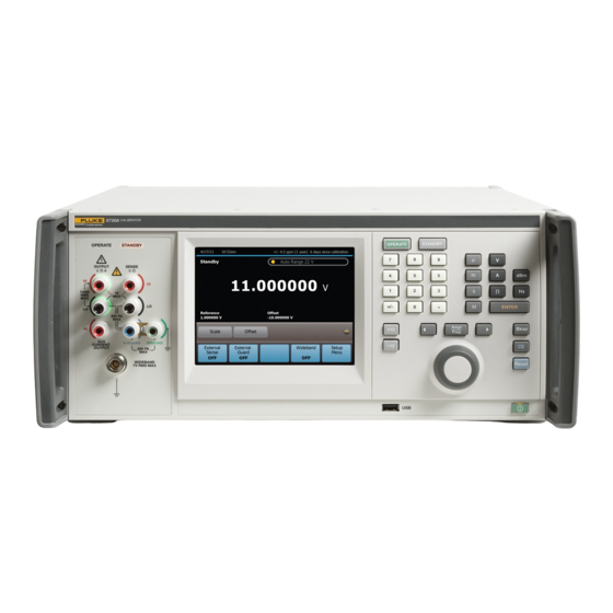
Page 57: Features
Chapter 3 Features Title Page Introduction ......................3-3 Front-Panel Features ..................3-3 Rear-Panel Features ................... 3-7... - Page 58 5730A Operators Manual...
-
Page 59: Introduction
This chapter is a reference for the functions and locations of the front and rear panel features. It also provides descriptions of each feature. Read this information before the 5730A Calibrator is used. Front-panel operation instructions for the Calibrator are in Chapter 4. Remote operation instructions are in Chapter 6. - Page 60 5730A Operators Manual Table 3-1. Front-Panel Features (cont.) Item Description deactivates the programmed output. The output automatically changes to STANDBY if: • is pushed • The output voltage is changed from <22 V to >22 V •...
- Page 61 Features Front-Panel Features Table 3-1. Front-Panel Features (cont.) Item Description Turn the Edit knob to the right to increase the output value of the active-edit digit. Turn the Edit knob to the left to decrease the output value of the active-edit digit. Error mode / edit keys ...
- Page 62 5730A Operators Manual Table 3-1. Front-Panel Features (cont.) Item Description Connection points for ac and dc current and voltage output, and resistance. The function of each OUTPUT binding post is defined below: The common binding post for all output functions including 5725A amplified voltage output, but not Option 5700A-03 Wideband AC or other auxiliary amplifier output.
-
Page 63: Rear-Panel Features
Features Rear-Panel Features Rear-Panel Features Rear-panel features (including all terminals, sockets, and connectors) are shown in Figure 3-2. Each rear-panel feature is briefly described in Table 3-2. hhp009.eps Figure 3-2. Rear-Panel Features Table 3-2. Rear-Panel Features Item Description The filter covers the air intake to keep dust and debris out of chassis. Fans ... - Page 64 5730A Operators Manual Table 3-2. Rear-Panel Features (cont.) Item Description Provides the input for an external signal onto which the Calibrator can be phase locked. (1 V rms to 10 V rms, 10 kΩ input impedance.) The connector shell is not connected directly to chassis ground. It is connected PHASE LOCK IN internally to the OUTPUT LO binding post.
-
Page 65: Front-Panel Operation
Chapter 4 Front-Panel Operation Title Page Introduction ......................4-3 Turn on the Calibrator ..................4-3 Warmup ......................4-4 Product Use ......................4-4 Reset the Calibrator ................... 4-4 Operate and Standby Modes ................4-4 Connect the Calibrator to a UUT ............... 4-5 Recommended Cable and Connector Types .......... - Page 66 5730A Operators Manual Linearity Check with Offset and Scale .............. 4-42 Set up the Calibrator ..................4-46 Setup Menu ....................4-46 Setup Menu Rules ..................4-47 Menu Description ..................4-48 Touchscreen Selections ................. 4-48 Instrument Setup ....................4-52 Uncertainty Information Menu ..............4-53 Set Output Limits ..................
-
Page 67: Introduction
To avoid electric shock, make sure the Product is safely grounded as described in Chapter 2. Make sure the rear power switch is on and then push to turn on the 5730A Calibrator. When the Calibrator is turned on, it takes approximately 50 seconds to complete its power-up process. -
Page 68: Warmup
“Operate” also shows on the display. When the STANDBY light above the output terminals is lit, all 5730A Calibrator binding posts except GROUND are open-circuited. “Standby” also appears on the display in this case. -
Page 69: Connect The Calibrator To A Uut
Avoid the use of nickel-plated connectors. Optimum results can be obtained with the 5730A-7003 Low Thermal EMF Test Leads. Cable requirements depend on the output function, amplitude, and frequency. Table 4-1... - Page 70 Output Function Cable Recommendations DC voltage Low Thermal EMF Test Leads AC voltage ≤10 kHz 5730A-7002 (banana plugs) or 5730A-7003 (spade lugs) AC current ≤2 A, ≤10 kHz (If external sensing is necessary, use a twisted DC current ≤2 A shielded pair.)
-
Page 71: When To Use External Sensing
DMM, refer to Figures 4-4B through 4-4D. For resistances of 19 kΩ or lower in two-wire mode, compensation circuitry inside the 5730A Calibrator is available to remove errors introduced by resistance in the path between the front panel terminals and the precision resistor. -
Page 72: Cable Connection Instructions
Use the connection in Figure 4-4D to calibrate the meter referenced at the end of its test leads. Cable Connection Instructions To connect the 5730A Calibrator to a UUT: 1. If the Calibrator is powered on, push , or . Either action sets the Calibrator to 0 mV in standby. - Page 73 Front-Panel Operation Connect the Calibrator to a UUT External External Sense Guard Calibrator SENSE INPUT Ω4-WIRE GUARD External External Calibrator Sense Guard INPUT Shielded Twisted Pair Shielded Twisted Pair External External Calibrator Sense Guard hhp011.eps Figure 4-1. UUT Connections: DC Voltage, AC Voltage ≤10 kHz...
- Page 74 5730A Operators Manual External External Sense Guard Calibrator Triaxial Cable SENSE INPUT 4-WIRE Triaxial Cable GUARD External External Calibrator Sense Guard Triaxial Cable SENSE INPUT 4-WIRE GUARD Note: Keep the SENSE leads as short as possible. Be careful not to exceed the capacitive load limit of 1000 pF up to 220 V, 600 pF 220 V to 1100 V.
- Page 75 Front-Panel Operation Connect the Calibrator to a UUT External External Calibrator Sense Guard (Front) SENSE INPUT 4-WIRE GUARD hhp013.eps Figure 4-3. UUT Connections: AC Current ≤2A 4-11...
- Page 76 5730A Operators Manual Calibrator SENSE INPUT Ω4-WIRE GUARD SENSE External External Sense Guard SOURCE Calibrator SOURCE 2-WIRE COMP SENSE Calibrator External External Sense Guard Calibrator 2-WIRE COMP hhp014.eps Figure 4-4. UUT Connections: Resistance 4-12...
- Page 77 Front-Panel Operation Connect the Calibrator to a UUT Calibrator Caution: Use connections with exposed plug tips for the ohms function only. External External Sense Guard COMP 2-WIRE Calibrator COMP COMP Calibrator External External COMP Sense Guard Calibrator 2-WIRE COMP COMP hhp015.eps Figure 4-4.
- Page 78 5730A Operators Manual 50 Ω Feedthrough Terminator 5730A supplied with the 5700A-03 option Cable supplied with the 5700A-03 option NOTE For wideband meters with higher than 50 Ω input impedence, use the 50 Ω feedthrough terminator at the meter connection end. For all wideband applications, take care to achieve a good 50 Ω...
-
Page 79: Set The Output
Front-Panel Operation Set the Output Set the Output While in normal output mode, the display can be divided into four horizontal sections. These sections are explained in Table 4-3. Table 4-3. Sections of the Display 12/21/12 10:52am +/- 59.0 ppm (1 year) 213 days since calibration Auto Range 22 V Standby 10.00000... - Page 80 5730A Operators Manual For the selections with indicators, the value shown is the value now in effect. For example, if the External Guard selections says OFF, then external guard is off and touching the selection will turn it on. To set the output, push this key sequence to select an output function and amplitude: [numeric keys] , [multiplier], [function] , , ...
-
Page 81: Dc Voltage Output
Front-Panel Operation Set the Output DC Voltage Output To set a dc voltage output: 1. Make sure the Calibrator is in standby (STANDBY annunciator lit). Push if necessary. 2. If the UUT is not connected, connect it now as described in this chapter under “Connect the Calibrator to a UUT.”... -
Page 82: Ac Voltage Output
5730A Operators Manual AC Voltage Output To set an ac voltage output: 1. Make sure the Calibrator is in standby (STANDBY annunciator lit). Push if necessary. 2. If the UUT is not connected, connect it now as described in this chapter under “Connect the Calibrator to a UUT.”... - Page 83 Front-Panel Operation Set the Output 9. Enter a frequency with the numeric keypad followed by or if necessary. The display now shows the amplitude and frequency of the entry. If an entry error is made, use to clear the most recently entered digit, or push to clear the display.
-
Page 84: Dc Current Output
5730A Operators Manual DC Current Output To set a dc current output: 1. Make sure the Calibrator is in standby (STANDBY annunciator lit). Push if necessary. 2. If the UUT is not connected, connect it now as described earlier in this chapter under “Connect the Calibrator to a UUT.”... - Page 85 Front-Panel Operation Set the Output In dc current output, the selections available at the bottom are: • Current Output • External Guard • Boost • Wideband • Setup Menu In addition, the Offset and Scale functions are available. The output range can be locked in dc current.
-
Page 86: Ac Current Output
5730A Operators Manual AC Current Output To set an ac current output: 1. Make sure the Calibrator is in standby (STANDBY annunciator lit). Push if necessary. 2. If the UUT is not connected, connect it now as described earlier in this chapter under “Connect the Calibrator to a UUT.”... - Page 87 Front-Panel Operation Set the Output 8. Enter a frequency with the numeric keypad (followed by if necessary). The display now shows the amplitude and frequency of the entry. If an entry error is made, push to clear the display, then reenter the value. If the most recent digit entered is in error, push ...
-
Page 88: Resistance Output
5730A Operators Manual The Current Output item selects one of three locations for non-boosted (current sourced by the Calibrator, for example) current output: • OUTPUT binding post (NORMAL, which is the OUTPUT HI binding post, also the default setting) •... - Page 89 Front-Panel Operation Set the Output If the “Ω Value Table” selection is used, touch the desired resistance value and to select it. To exit the menu, touch the “x” on the top right of the table. 5. Push or if necessary. 6.
- Page 90 5730A Operators Manual In resistance output, the selections available at the bottom are: • External Sense • External Guard • 2-wire Compensation • Wideband • Setup Menu In the resistance function, two features are available to enhance accuracy: four-wire sensing and two-wire compensation. Two-wire compensation works with either a two- wire connection or a four-wire connection to a two-wire ohmmeter.
-
Page 91: Wideband Ac Voltage Output (Option 5700A-03)
Front-Panel Operation Set the Output Wideband AC Voltage Output (Option 5700A-03) To set an output from the Wideband AC Module (Option 5700A-03), proceed from or the power-up state as follows: 1. Make sure the Calibrator is in standby (STANDBY annunciator lit). Push if necessary. - Page 92 5730A Operators Manual 9. The display now shows the amplitude of the entry. If an entry error is made, push to clear the display, then reenter the value. If the most recent digit entered is in error, push to clear that digit. The illustration of the display below assumes an entry of...
-
Page 93: Variable Phase Output
Front-Panel Operation Variable Phase Output 11. Push . The Calibrator clears the entry from the entry bar toward the bottom and displays in the larger area above. No voltage is available at the WIDEBAND Type “N” coaxial connector until is pushed. 12. -
Page 94: Phase Locking To An External Signal
5730A Operators Manual 5. The phase can now be changed by entering a value with the numeric keypad, turning the knob, or touching a point on the phase scale. 3/14/2013 10:52am +/- 62.0 ppm (1 year) 213 days since calibration... -
Page 95: Auxiliary Amplifier Use
Front-Panel Operation Auxiliary Amplifier Use 6. Touch Phase Reference to toggle between INTERNAL (the default, not locked to anything) and EXTERNAL. 7. If the Calibrator cannot lock onto the external signal for any reason, it shows the message below: 3/14/2013 10:52am +/- 62.0 ppm (1 year) 213 days since calibration Standby... -
Page 96: 5725A Amplifier Output
5730A Operators Manual 5725A Amplifier Output Warning Boosted voltage operation produces high voltage at higher current levels than normally available from the Product. During boosted voltage operation, the potential risk of injury or fatal accident is greater than during normal operation. -
Page 97: 52120A Transconductance Amplifier Output
Front-Panel Operation Error Mode Operation 52120A Transconductance Amplifier Output The 52120A Amplifier boosts ac and dc current. A maximum of three 52120A amplifiers may be connected together to the Calibrator. When their outputs are connected in parallel, they produce two (for two 52120As) or three (for three 52120As) times the current output, providing up to 300 A of dc current and 360 A rms ac current. -
Page 98: Error Mode Overview
5730A Operators Manual Error Mode Overview This section explains how to use Error Mode in general. After the overview, a step-by- step procedure explains how to use this mode to read UUT error for each Calibrator output function. Enter Error Mode To start Error Mode, turn the rotary knob, push an arrow key, or push . -
Page 99: Use Error Mode
“Set the Output.” Use the output adjustment controls as necessary to get a reading on the UUT equal to the original entry on the 5730A Calibrator. To increment or decrement a higher-order digit, push . As the reference value is approached, work progressively back towards the least-significant digit on the Calibrator display as necessary by pushing . -
Page 100: Read The Uut Error: Resistance Output
(illustrated below) equal to the reading on the UUT. To adjust a higher- order digit, push . As the reference value is approached, work progressively back towards the least-significant digit on the 5730A Calibrator display as necessary by pushing . It is only necessary to go one digit past the least significant digit of the UUT. -
Page 101: Offset Error
Front-Panel Operation Introduction to Offset, Scale, and Linearity Errors Offset Error Offset error can be measured directly by finding the Calibrator output that causes a meter reading of 0 V. This error is called an offset because it reflects a fixed error that is present in all meter output readings. -
Page 102: Linearity Error
The error value is computed relative to the selected full-scale point. The formula for linearity error is: (Nominal setting) – (Adjusted 5730A Setting) Linearity Error= (Nominal Full Scale) Where the “nominal setting”... -
Page 103: Combine The Error Types
Front-Panel Operation Introduction to Offset, Scale, and Linearity Errors Figure 4-9 illustrates linearity error with both offset and scale errors assumed to be zero. The formula for linearity error yields: (10.0 – 9.993) Linearity Error= = 0.000352 = +0.0352 % 19.9 19.900 V Linear Response... -
Page 104: Program An Offset
The Offset selection can be used when in the dc voltage or current function any time it is necessary to offset the 5730A Calibrator output by a fixed amount. The Offset selection is shown by touching the + icon on the right of the display above the bottom row of selections. -
Page 105: Program A Scale Factor
“Linearity Checking With Offset and Scale”.) To program a scale factor: Set the 5730A Calibrator to output a level just below the UUT full-scale endpoint. For example, use 19.9 V for a UUT that ranges at 20 V. Adjust the Calibrator output with the rotary knob (and arrow keys if necessary) until the UUT reads the selected correct output level (19.9 V in this example). -
Page 106: Linearity Check With Offset And Scale
Operators Manual Linearity Check with Offset and Scale With the 5730A Calibrator offset and scaling features, a UUT offset and scale errors can be removed to isolate and display linearity error. The subsequent procedure is an example that uses the Offset and Scale selection to determine both scale and linearity error of a 4 1/2-digit DMM. - Page 107 Front-Panel Operation Linearity Check with Offset and Scale Note The message “Error >+999.9999%” occurs because in this case the reference voltage is 0. 3. Touch Offset to identify this as the DMM zero-scale endpoint. The display changes 12/21/12 10:52am +/- 3% (1 year) 213 days since calibration Standby Auto Range 220 mV 1.3000...
- Page 108 5730A Operators Manual 5. Use the output adjustment controls to adjust the Calibrator output for a reading of 19.9 V (the reference value) on the DMM. The displays change to: 4/18/2013 14:33 +/- 4.3 ppm (1 year) 213 days since calibration...
- Page 109 Front-Panel Operation Linearity Check with Offset and Scale The 10.000208 V output setting is calculated by the Calibrator with the subsequent equation: 19.9 V – 19.903 V = 1.0001508 19.9 V This is applied to 10 V to yields: 10 V x 1.0001508 = 10.001508 V The 1.3 mV zero offset is then subtracted: 10.001508 V −...
-
Page 110: Set Up The Calibrator
• Calibration- The items in this submenu are used to activate calibration to external standards, Calibration Check, DC Zeros, and to verify or adjust the 5730A Calibrator calibration to its specifications. The Calibration submenu and process is explained in greater detail in Chapter 7. -
Page 111: Setup Menu Rules
Conversely, from the Remote Port menu, touch Instrument Setup to go up one level, Setup Menu to go up two levels. An Exit or Cancel selection in the lower right of the display closes the menus or stops a process. The 5730A Calibrator then returns to the normal operation screen. 4-47... -
Page 112: Menu Description
5730A Operators Manual Menu Description A menu item that leads to a submenu with multiple selections has a black and amber title bar on top followed by a list of the items in the submenu. The Instrument Setup menu is... - Page 113 Front-Panel Operation Set up the Calibrator Some selections do not have submenus beneath them or do not include changeable items. For example, in the display below, the About this Instrument selection has no changeable items. Setup Menu Calibration Instrument Setup DC Zero Remote Port Artifact Calibration...
- Page 114 5730A Operators Manual There are selections without a submenu listed beneath them that are used to start processes. For example, the Run DC Zero selection from the Calibration menu starts the DC Zero process (see Chapter 7). Setup Menu Calibration...
- Page 115 Front-Panel Operation Set up the Calibrator Touchscreen selections with several possible values look like the Calibration Interval item shown in the screen above. Touch the selection to open another menu with a selection for each possible choice as shown below. Instrument Uncertainty Setup Menu...
-
Page 116: Instrument Setup
5730A Operators Manual Some of the setup menus have a Restore Factory Defaults selection. If this selection is touched, a confirmation is requested. Touch Restore to reset the Calibrator to factory defaults or Cancel to make no changes. Instrument Setup... -
Page 117: Uncertainty Information Menu
Front-Panel Operation Instrument Setup AC Transfer Off stays active until the Calibrator is reset or the power is turned off. For remote control applications, the same feature is accessible through the remote command Transfer Off. Send the command Transfer On to restore internal ac transfers to normal operation. -
Page 118: Set Output Limits
5730A Operators Manual Set Output Limits An output limit feature is available to help prevent accidental damage to a UUT from overcurrent or overvoltage conditions. The maximum positive and negative allowable voltage or current output can be preset with this feature. Entry limits that are set prevent any input greater than the limit from being activated by entry through the front-panel keys or the output adjustment controls. -
Page 119: Select Boost Amplifiers
-10.00030, the error is -30 ppm or -0.0030 %. The 5730A Calibrator has two methods of scaling the UUT error. The first method, called the “nominal” method is used in the Fluke Calibration 5700A, 5720A, 5502A, and 5522A calibrators. - Page 120 5730A Operators Manual The second method is called “true value”. Both methods can be used in this Calibrator. The nominal method of error calculation uses the formula: reference value – edit value reference value The nominal method is useful to check the error of the Calibrator itself, when its performance is verified against a more accurate measuring device.
-
Page 121: Instrument Settings
A long-life lithium battery keeps the clock/calendar running during power- off periods. If the battery in the Calibrator should ever need replacement, contact a Fluke Calibration Service Center. To set the date or time, enter a security passcode. Touch Setup Menu>Instrument Settings>Date/Time. -
Page 122: Language
5730A Operators Manual Language To select the display language used for the 5730A Calibrator UI: 1. Touch Setup Menu>Instrument Settings>Language. 2. Touch the necessary language from the screen. The choices are: • English • French • Spanish • Simplified Chinese •... -
Page 123: Remote Interface Setup
Chapter 5 Remote Interface Setup Title Page Introduction ......................5-3 GPIB (IEEE-488) Interface................5-3 Use the IEEE-488 Port for Remote Control ..........5-3 IEEE-488 Bus Restrictions ................5-3 Bus Setup Procedure ..................5-4 IEEE-488 Interface Configuration ..............5-4 Bus Communication Overview ..............5-5 RS-232 Serial Interface .................. - Page 124 5730A Operators Manual...
-
Page 125: Introduction
GPIB (IEEE-488) Interface Use the IEEE-488 Port for Remote Control The 5730A Calibrator is fully programmable for use on the IEEE Standard 488.1 interface bus (IEEE-488 bus). The interface is also designed in compliance with supplemental standard IEEE-488.2. Devices connected to the bus in a system are designated as talkers, listeners, talker/listeners, or controllers. -
Page 126: Bus Setup Procedure
Operators Manual Bus Setup Procedure To set up the 5730A Calibrator on the IEEE-488 bus, only a choice of address and the connection to a controller is necessary. To set up the bus: 1. With the Calibrator off, attach the IEEE-488 cable to the rear panel IEEE-488 connector. -
Page 127: Bus Communication Overview
RS-232 Serial Interface Use the RS-232 Port for Remote Control This procedure is intended for those who use the 5730A Calibrator serial interface for remote control from a terminal or computer with a serial interface. This section describes how to set up the RS-232 interface for remote control with protocol similar to IEEE-488. -
Page 128: Rs-232 Interface Specifications
Refer to the specifications for the peripheral device, and proceed as follows to set up the serial interface for the application: 1. With the 5730A Calibrator power off, connect a 9-pin D subminiature RS-232 null- modem cable such as Fluke accessory RS43 to the rear panel RS-232 connector and to the peripheral device. -
Page 129: Serial Remote Control Setup Procedure
5. Touch Exit to exit the Setup Menu. Exceptions for Serial Remote Control When the RS-232 port is used to remotely control the 5730A Calibrator, either interactively with a terminal or under computer control, operation is the same as with an IEEE-488 controller connected to the IEEE-488 port for control. -
Page 130: Ethernet Interface
An internet (IP) address is necessary for all internet and TCP/IP communications. If DHCP is enabled, the 5730A Calibrator will use the dynamic address supplied by the DHCP server. If the DHCP server fails to supply the address, the IP address will be shown as "0.0.0.0". -
Page 131: Set A Static Internet Address
*RST command. Configure the General Network Socket Port In order to communicate with each other, a client computer and the 5730A Calibrator must use the same socket port number. The default port is 3490. Typically, the default port does not need to be changed. If the socket port must be changed, enter the Socket Port number supplied by the network administrator. -
Page 132: Configure The Lan Default Gateway
The default gateway IP address is the IP address of a gateway (router) attached to the same network as the device. When the 5730A Calibrator detects that a client computer is not on the same network (using the network number), the data is sent through the gateway to reach the host computer. -
Page 133: Establish An Ethernet Connection
Establish an Ethernet Connection Establish an Ethernet Connection Telnet is the easiest method of establishing an Ethernet connection with the 5730A Calibrator. Telnet is a client-server protocol, based on TCP. The Telnet Protocol provides a fairly general, bi-directional, eight-bit byte oriented communications method. Telnet is available on all UNIX servers and on most PCs. -
Page 134: Use Of Usb 2.0 Remote Control
3. Touch USB. 4. Touch Exit to exit the Setup Menu. When the USB port is used to remotely control the 5730A Calibrator, either interactively with a terminal or under computer control, operation is the same as with an RS-232 controller connected to the RS-232 port for control. -
Page 135: Remote Commands And Syntax
Chapter 6 Remote Commands and Syntax Title Page Introduction ......................6-3 Parameter Syntax Rules ................. 6-3 Extra Space Characters .................. 6-4 Terminators....................6-4 Incoming Character Processing ..............6-4 Response Message Syntax ................6-5 Input Buffer Operation ..................6-5 Commands ......................6-6 Multiple Commands .................. - Page 136 5730A Operators Manual...
-
Page 137: Introduction
For example: “OUT 1 V, 100 HZ.” 2. Numeric parameters may have up to 255 significant figures and their exponents may range from -32000 to +32000. The useful range for 5730A Calibrator programming is ± 2.2 E-308 to ± 1.8 E308. -
Page 138: Extra Space Characters
Table 6-5 contains examples for commands whose parameters are not self-explanatory. Terminators To signal the end of a response sent to the controller, the 5730A Calibrator sends a “terminator.” For response message terminators, the Calibrator sends the ASCII character Line Feed with the EOI control line held high. The subsequent characters are recognized by the Calibrator as terminators when encountered in incoming data: •... -
Page 139: Response Message Syntax
(See Table 5-2 for details.) Input Buffer Operation As the 5730A Calibrator receives each data byte from the controller, it places the bytes in a portion of memory called the input buffer. The input buffer holds up to 128 data bytes and operates in a first in, first out fashion. -
Page 140: Commands
Multiple Commands Controllers may send commands all at once, or one at a time. To set the output to 100 mV dc and then place the 5730A Calibrator into operate, two separate commands may be used: OUT 100 MV <CR/LF>... -
Page 141: Sequential And Overlapped Commands
*OPC?, and *WAI in Table 6-5 for more information.) Commands Ignored When Not in Remote The 5730A Calibrator can receive and execute most commands in either local or remote state. Commands that change the state of the Calibrator are prevented from executing unless the Calibrator is in the remote state. -
Page 142: Definition: Queries And Commands
Table 6-1 lists the functional elements of commands described by the IEEE-488.2 standard that are used by the 5730A Calibrator. This table is for those who have a copy of the standard and want to use it to pursue additional information. The standard provides... - Page 143 Remote Commands and Syntax Commands Table 6-1. Functional Elements of Commands Element Function A sequence of zero or more PROGRAM MESSAGE PROGRAM MESSAGE UNIT elements, each of which is separated by a PROGRAM MESSAGE UNIT SEPARATOR element A command, programming data, or query received by PROGRAM MESSAGE UNIT the device.
-
Page 144: Interface Messages (Ieee-488 Only)
IEEE-488 standards define interface messages. Table 6-2 lists the interface messages that the 5730A Calibrator accepts. Table 6-3 lists the interface messages that the 5730A Calibrator sends. The mnemonics listed in the tables are not sent as literal statements as commands are. - Page 145 Remote Commands and Syntax Commands Table 6-2. Interface Messages Accepted by the Calibrator (cont.) Mnemonic Name Function Addresses a specific device on the bus as a talker. The controller My Talk sends MTA automatically whenever it directs a device-dependent or Address common query to a specific instrument.
-
Page 146: Use Of *Opc?, *Opc, And *Wai
*OPC?, except the program must read the ESR to detect the completion of all operations. The *WAI command causes the 5730A Calibrator to wait until any prior commands have been completed before continuing on to the next command, and takes no other action. - Page 147 Remote Commands and Syntax Commands Table 6-4. Command Summary by Function Error Mode Commands ADJOUT? Returns the adjusted output magnitude and frequency ERR_REF Selects the denominator for UUT error calculations. ERR_REF? Returns the denominator used to compute UUT error. INCR Increments or decrements the output MULT Multiplies the reference by a value and establishes a new reference...
- Page 148 5730A Operators Manual Table 6-4. Command Summary by Function (cont.) Output Commands BOOST Activates or deactivates an auxiliary amplifier DBMOUT? Returns the output amplitude and frequency, but in dBm if ac V OPER Activates the Calibrator output if it is in standby...
- Page 149 Remote Commands and Syntax Commands Table 6-4. Command Summary by Function (cont.) Remote Interface Parameter Setting Commands SP_EOF Sets the End-Of-File (EOF) string SP_EOF? Returns the End-Of-File (EOF) string Sets baud, terminal or computer mode, stall method, data bits, stop bits, SP_SET parity, and End-Of-Line (EOL) string Returns baud rate, terminal or computer mode, stall method, data bits, stop...
- Page 150 5730A Operators Manual Table 6-4. Command Summary by Function (cont.) Calibration, Testing, and Diagnostics Commands for the Calibrator CAL_ADJ Does the internal portion of calibration CAL_CHK Starts calibration check CAL_CLST? Returns a group of calibration constant names and their values...
-
Page 151: Fault Queue
Remote Commands and Syntax Commands Table 6-4. Command Summary by Function (cont.) Calibration, Testing, and Diagnostics Commands for the Calibrator (cont.) DIAGFLT Sets the Calibrator response to faults in remote diagnostics DIAGFLT? Returns the Calibrator response to faults in remote diagnostics OHMSREF? Returned calculated resistance reference (Main software revision H and after) - Page 152 5730A Operators Manual Table 6-5. Commands ADDR Description Sequential command. Ignored if not in remote. Sets the GPIB interface bus address. Parameter Bus address ADDR 4 Example Sets the GPIB interface bus address to 4 ADDR ? Description Sequential command. Gets the GPIB interface bus address.
- Page 153 Remote Commands and Syntax Commands Table 6-5. Commands (cont.) BRIGHTNESS Sets the brightness of the GUI display. Description Integer, 0 to 100, where 0 is dimmest and 100 is brightest. Parameter BRIGHTNESS 50 Example Sets the display to half brightness (the default value). BRIGHTNESS? Returns the brightness setting.
- Page 154 5730A Operators Manual Table 6-5. Commands (cont.) CAL_CLST? Sequential command. Description Returns a list of names values of a particular group of calibration constants. (Returns active calibration constants) CHECK (Returns calibration check constants) Parameter PREV (Returns previous calibration constants) (String) "<EOL>...
- Page 155 Remote Commands and Syntax Commands Table 6-5. Commands (cont.) CAL_DATE? Sequential command. Description Returns the date of the most recent calibration of the specified type. B5725 (Last 5725A Amplifier calibration) (Last calibration of the Calibrator) Parameter WBFLAT (Last wideband flatness calibration) WBGAIN (Last wideband gain calibration) ZERO...
- Page 156 5730A Operators Manual Table 6-5. Commands (cont.) CAL_REF Overlapped long-term command, ignored if not in remote. Calibrates the internal references for the main output functions based on comparison to an externally-applied standard. To calibrate the Calibrator, the controller must send a...
- Page 157 Remote Commands and Syntax Commands Table 6-5. Commands (cont.) CAL_RPT? Sequential command. Description Returns a report for a specified calibration activity (see Chapter 6 for format details). (Output change report for calibration) Parameter CHECK (Output change report for calibration check) RAW (A list of all calibration constants) (String) "<EOL>...
- Page 158 5730A Operators Manual Table 6-5. Commands (cont.) CAL_SHIFT? Sequential command. Description Returns a particular set of output shifts from a particular range. (Output changes due to calibration check) CHECK (All output changes due to calibration check) Parameter Range identifier from Table 5-4 (String) "<EOL>...
- Page 159 Remote Commands and Syntax Commands Table 6-5. Commands (cont.) CAL_SLST? Sequential command. Description Returns a group of calibration constant shifts due to a calibration activity. (All output changes due to calibration) Parameter CHECK (All output changes due to calibration check) (String) "<EOL>...
- Page 160 5730A Operators Manual Table 6-5. Commands (cont.) CAL_TEMP Sequential command, ignored if not in remote. Sets the temperature for calibration. This should be done before sending CAL_REF, Description CAL_WBFLAT, CAL_WBGAIN, or CAL_CHK commands. Once set, the temperature is used for all calibration activities until it is changed. If the temperature is not set before a calibration activity, the Calibrator uses a default of 23.0 °C.
- Page 161 Remote Commands and Syntax Commands Table 6-5. Commands (cont.) CAL_WBGAIN Overlapped long-term command, ignored if not in remote. Does Wideband AC Module (Option 5700-03) gain calibration. There are two different calibration procedures for the wideband module: gain and flatness. Wideband gain is to be done at every calibration cycle.
- Page 162 5730A Operators Manual Table 6-5. Commands (cont.) *CLS Sequential command. Description (Clear status.) Clears the ESR, ISCR, the fault queue, and the RQS bit in the status byte. This command terminates pending operation complete commands (*OPC or *OPC?). Parameter None CUR_POST Sequential command, ignored if not in remote.
- Page 163 Remote Commands and Syntax Commands Table 6-5. Commands (cont.) DHCP Description Sequential command. Ignored if not in remote. Enables/disables DHCP (Dynamic Host Configuration Protocol) for LAN operation. Parameter ON (enables DHCP operation) OFF (disables DHCP operation) DHCP? Description Sequential command. Returns the current state of the DHCP configuration. Parameter None Response...
- Page 164 *IDN? response. It also accepts BTYPE VB5205 and implements it as if Description BTYPE VBNONE was sent, as a Fluke 5205A cannot be connected to the 5730A Calibrator. (Integer) 5700 selects 5700A emulation; 5720 selects 5720A emulation; anything else Parameter selects normal 5730A behavior.
- Page 165 Remote Commands and Syntax Commands Table 6-5. Commands (cont.) EOL? Sequential command. Returns the end of line terminator for outgoing data for a specified Description remote port. Parameter 1. SERIAL, USB, ENET Response String EOL? SERIAL Example Returns CRLF if the serial end of line terminator is set to CRLF. ERR_REF Description Selects the denominator for UUT error calculations.
- Page 166 5730A Operators Manual Table 6-5. Commands (cont.) *ESR? Sequential command. Description Returns the byte from the Event Status Register and clears the register. The ESR is described under "Check the Calibrator Status." Parameter None Response (Integer) Decimal equivalent of the register byte.
- Page 167 Remote Commands and Syntax Commands Table 6-5. Commands (cont.) FORMAT Sequential command, ignored if not in remote. Use with extreme care. Restores the contents of the non-volatile memory to factory Description defaults. The non-volatile memory holds calibration constants and setup parameters. All calibration data is lost permanently.
- Page 168 5730A Operators Manual Table 6-5. Commands (cont.) *IDN? Sequential command. Description Returns Calibrator model number and firmware version letters for the main, inguard, and if attached, the 5725A Amplifier CPU. Parameter None (String, string, 0, string) A message containing four fields separated by commas, as follows:...
- Page 169 Remote Commands and Syntax Commands Table 6-5. Commands (cont.) ISCE Sequential command. Description Loads a byte into the Instrument Status Change Enable register described under "Check the Calibrator Status." Parameter The decimal equivalent of the binary number to load into the register. ISCE 56 Example Enables bits 3 (BOOST), 4 (RCOMP), and 5 (RLOCK) in the Service Request Enable...
- Page 170 5730A Operators Manual Table 6-5. Commands (cont.) LCOMP_52120? Sequential command. Returns the current state of inductance compensation for Description attached 52120As. Parameter None Response String LCOMP_52120? Example Returns ON if LCOMP is enabled. LIMIT Sequential command, ignored if not in remote.
- Page 171 Remote Commands and Syntax Commands Table 6-5. Commands (cont.) MACADDR? Sequential command. Returns MAC/HW address for LAN communication. The MAC Description address is a unique assigned value and cannot be changed. Parameter None Response String MACADDR? Example Returns six groups of hexadecimal numbers separated by colons (for example, 01:23:45:67:89:ab) MULT Overlapped command, ignored if not in remote.
- Page 172 5730A Operators Manual Table 6-5. Commands (cont.) OLDREF Overlapped command, ignored if not in remote. Description Sets the Calibrator output to the previously-programmed reference value. (The same as pushing the in local operation.) Parameter None ONTIME? Sequential command. Description Returns the time in minutes since the Calibrator was turned on.
- Page 173 Remote Commands and Syntax Commands Table 6-5. Commands (cont.) *OPT? Sequential command. Description Returns a list of analog modules installed in the Calibrator, including any auxiliary amplifiers that are attached. Parameter None Response (Series of strings) A list of the modules and auxiliary amplifiers, separated by commas. Example "5725A Attached","52120 Attached"...
- Page 174 5730A Operators Manual Table 6-5. Commands (cont.) PHASE? Sequential command. Description Returns the phase angle of the variable phase output signal, with respect to the main output signal. Parameter None Response (Integer) Phase in degrees (0 to 180,-179 to 0, 0 if the output is not ac) PHASELCK Overlapped command, ignored if not in remote.
- Page 175 Remote Commands and Syntax Commands Table 6-5. Commands (cont.) *PUD Sequential command. Description (Protected user data command.) Allows a string of bytes to be stored in nonvolatile memory. The Calibrator secure state must be set to off. See the RPT_STR command. #0 \<user data\>...
- Page 176 5730A Operators Manual Table 6-5. Commands (cont.) RCOMP Overlapped command, ignored if not in remote. Description While a resistance output 19 kΩ or lower is selected, RCOMP activates or deactivates two-wire ohms compensation circuitry. (Turns on the two-wire compensation circuitry)
- Page 177 Remote Commands and Syntax Commands Table 6-5. Commands (cont.) RPT_STR? Sequential command. Description Returns the user report string. The user report string can be read on the Display in local operation, and appears on calibration reports. Parameter None Response (String) Up to 40 characters *RST Overlapped command, ignored if not in remote.
- Page 178 5730A Operators Manual Table 6-5. Commands (cont.) SP_EOF Sequential command, ignored if not in remote. Description Sets the End-Of-File character string for the RS-232-C serial interface. The EOF setting is saved when the power is turned off. ASCII code (decimal) for the first character...
- Page 179 Remote Commands and Syntax Commands Table 6-5. Commands (cont.) SP_SET? Sequential command. Description Returns the serial port settings contained in nonvolatile memory. (Integer) One of these baud rates: 9600, 19200, 38400, 57600 or 115200 (String) TERM or COMP (Response type) (String) XON, RTS, or NOSTALL (Stall method) Response...
- Page 180 5730A Operators Manual Table 6-5. Commands (cont.) STATE? Sequential command. Description Returns the long-term state of the Calibrator. Parameter None 1. (Integer) Gross state, with the subsequent responses: Operating Calibration, wideband positive gain Self diagnostics Calibration, wideband negative gain Self diagnostics halted by a fault...
- Page 181 Remote Commands and Syntax Commands Table 6-5. Commands (cont.) SUBNETMASK? Description Sequential command. Returns Ethernet subnet mask for LAN communication. Parameter None Response String SUBNETMASK? Example Returns 255.255.254.0 if the subnet mask was previously set to this value. *TST? Sequential command, ignored if not in remote. Initiates a series of self-tests, then returns a "0"...
- Page 182 5730A Operators Manual Table 6-5. Commands (cont.) *WAI Sequential command. Description (Wait-to-Continue.) This command prevents further remote commands from being executed until all previous remote commands have been executed. (See also *OPC.) Parameter None If an OUT command had been sent, it can cause the Calibrator to wait until the output...
- Page 183 Remote Commands and Syntax Commands Table 6-6. Serial Remote Control Commands LOCAL Sequential command. Description Enables the local state. This command duplicates the IEEE-488-GTL (Go to Local) message. Parameter None LOCKOUT Sequential command. Description Enables the local lockout state. This command duplicates the IEEE-488 LLO (Local Lookout) message.
-
Page 184: Local-To-Remote State Transitions
Operators Manual Local-to-Remote State Transitions The 5730A Calibrator can be operated either locally from the front panel, or remotely with remote control commands. In addition to front panel and remote control operation, the controller can be placed in a local lockout condition at any time by remote command. - Page 185 Remote Commands and Syntax Local-to-Remote State Transitions • Remote with Lockout The remote with lockout state can be entered from remote or local with lockout, but not directly from local. Remote with lockout is similar to the remote state, but restricted: the Local Control is not shown on the display.
-
Page 186: Check The Calibrator Status
Operators Manual Check the Calibrator Status The controller has access to six status registers for the 5730A Calibrator, which indicate the Calibrator conditions in the as shown in Figure 6-1. Each register bit is explained under separate headings for each register. Table 6-9 lists each register and its remote commands. - Page 187 Remote Commands and Syntax Check the Calibrator Status Instrument Status Change Enable Register & Read using ISCE? & Write using ISCE & & & & & & & & & & & & & & Instrument Status Change Register Read using ISCR? Bit Change from 0 1 or 1 Instrument Status...
-
Page 188: Serial Poll Status Byte
The most important and frequently used register is the serial poll status byte, which is how the 5730A Calibrator responds to a serial poll. This byte is cleared (set to 0) when the power is turned on. A serial poll cannot be done if the RS-232C port is used as the remote control interface. -
Page 189: Event Status Register
Remote Commands and Syntax Check the Calibrator Status Event Status Register The Event Status Register is a two-byte register that the higher eight bits are always 0, and the lower eight bits except bits 6 and 1 represent various conditions of the Calibrator. The ESR is cleared (set to 0) when the power is turned on, and every time it is read. -
Page 190: Read The Esr And Ese
5730A Operators Manual Read the ESR and ESE To read the contents of the ESR, send the remote command, *ESR?. The ESR is cleared (set to 0) every time it is read. To read the contents of the ESE, send the remote command, *ESE?. -
Page 191: Read The Isr, Iscr, Or Isce
Remote Commands and Syntax Check the Calibrator Status ZERO CAL When 1, DC Zero Cal is necessary. ACXFER When 1, ac/dc transfer is active. SETTLED When 1, the output has stabilized to within specification. REMOTE When 1, the Calibrator is under remote control. WBND When 1, the wideband is active. - Page 192 5730A Operators Manual Note The Calibrator Main CPU software revision levels can be checked with the Instmt Config Menu, or *IDN? remote command. After the Calibrator has encountered a fault, do one of the subsequent actions to reenable the OPER command: 1.
-
Page 193: Operator Maintenance And Calibration
Fuse Replacement ....................7-2 Clean the Air Filter .................... 7-4 Clean the Exterior ....................7-5 User-Replaceable Parts ..................7-5 5730A Calibration ....................7-7 The Artifact Calibration Process ..............7-7 Establish Traceability ..................7-8 Calibration Reports ..................7-8 Range Adjustment ..................7-8 DC Zeros ...................... -
Page 194: Introduction
Introduction This chapter explains how to do the routine maintenance and calibration tasks necessary to keep the 5730A Calibrator in optimal operating condition. For intensive maintenance tasks such as troubleshooting or repair, contact a Fluke Calibration Service Center. See “How to Contact Fluke Calibration” in Chapter 1. - Page 195 Operator Maintenance and Calibration Fuse Replacement hhp003.eps Figure 7-1. Access the Fuse...
-
Page 196: Clean The Air Filter
5730A Operators Manual Clean the Air Filter Caution Damage caused by overheating can occur if the area around the fan is restricted, the intake air is too warm, or the air filter becomes clogged. To prevent Product damage, make sure that the filter is completely dry before reinstallation. -
Page 197: Clean The Exterior
Clean the Exterior Clean the Exterior To keep the 5730A Calibrator looking new, clean the case, front panel keys, and display with a soft cloth slightly dampened with either water or a non-abrasive mild cleaning solution that is not harmful to plastics. - Page 198 5730A Operators Manual hhp224.eps Figure 7-3. Replaceable Parts...
-
Page 199: 5730A Calibration
When finished with artifact calibration, but before the new constants are saved, the 5730A Calibrator presents the proposed adjustments as +/- ppm of range and percentage change in specification for each range and function. A list of changes can be saved to a file through the USB host port on the front of the Calibrator, or send them to a computer through either the serial port, USB device port, Ethernet port, or the IEEE-488 port. -
Page 200: Establish Traceability
Calibration Reports The 5730A Calibrator stores two sets of calibration constants: the set currently in use and the old set from the previous calibration. This gives the Calibrator the ability at any time to produce a calibration report of the differences between the present settings and the settings that were in effect before the last calibration. -
Page 201: Dc Zeros Reminder
Operator Maintenance and Calibration Calibration 3. Touch Run DC Zero to start the dc zeros routine. The status of the dc zero calibration is shown as the Calibrator progresses through a series of steps. When completed, the Calibrator shows “Calibration complete”. Note If the Calibrator is not warmed up, the display prompts to continue or cancel the DC Zeros function. -
Page 202: Calibration Security Passcode
“How to Contact Fluke Calibration” in Chapter 1. Artifact Calibration The 5730A Calibrator must be calibrated to external standards at the beginning of the calibration cycle. The length of the cycle (24 hours, 90 days, 180 days, or one year) is selected in a Setup Menu described in Chapter 4. -
Page 203: When To Adjust Calibrator Accuracy
2 ppm 10 Ω to 100 MΩ Calibration Procedure Before this procedure is started, make sure the 5730A Calibrator is powered on and has completed the appropriate warm-up period. Follow this procedure to calibrate the main output functions: 1. Touch Setup Menu>Calibration. The calibration menu is shown. - Page 204 6. If the entered value is not between 9 V and 11 V, an error message is shown. The process can be started over from this point with a calibrated 732B. Push to start the calibration procedure. As the 5730A Calibrator does self-calibration, it will indicate what is happening on the display.
- Page 205 Operator Maintenance and Calibration Calibration Resistance Stadard Calibrator hhp028.eps Figure 7-5. 742A-1 and 742A-10k External Calibration Connections 12. Disconnect the 10 kΩ standard, and connect the Calibrator to the 1 Ω standard. Enter the true value of the 1 Ω standard. If the standard is not between 0.9 Ω and 1.1 Ω, an error message appears, and the user can start over from this point with another standard.
-
Page 206: Range Adjustment
Range adjustment is accomplished by adjusting a range constant, which is an additional gain multiplier. Although range calibration is not needed in order to meet total uncertainty specifications, they are useful for tuning the 5730A Calibrator so that its values are closer to in-house standards. -
Page 207: Range Adjustment
Operator Maintenance and Calibration Range Adjustment 1. Touch Setup Menu>Calibration>Range Adjustment to bring up the Range Adjustment menu shown below: Range Setup Menu Calibration Adjustment Resistance Base 19 Values Base 10 Values Exit hhp189.eps 2. Touch DCV to show the next menu shown below: Range Setup Menu Calibration... - Page 208 5730A Operators Manual 3. Touch 220 V and this screen is shown: Range Setup Menu Calibration Adjustment 220 V Enter nominal value then press ENTER. Cancel hhp216.eps 5. Connect the 732B, 8508A (Null Detector), and 752B in a 10:1 configuration, as shown in Figure 7-6.
- Page 209 Operator Maintenance and Calibration Range Adjustment Null Detector External External Sense Guard Calibrator 752A Voltage Divider Standard 732B Voltage Reference Standard INPUT NULL DETECTOR GND GRD OUTPUT REFERENCE STANDARD 732B DC STANDARD AC PWR IN CAL CHARGE LOW BAT 1.018V CHASSIS 10V COM 1.018V COM...
-
Page 210: Calibrate The Wideband Ac Module (Option 5700A-03)
Operators Manual Calibrate the Wideband AC Module (Option 5700A-03) The Wideband AC Module (Option 5700A-03) can be installed in the 5730A Calibrator. The module needs to be calibrated for both gain and flatness. The gain should be calibrated when the 5700A-03 main output functions undergo their routine calibration. -
Page 211: Wideband Flatness Calibration Procedure
Touch Discard to delete the results of the calibration. In both cases, the calibration screen is shown after the results are saved or deleted. Wideband Flatness Calibration Procedure This calibration procedure and the full verification of the 5730A Calibrator should be done every 2 years. For flatness calibration: Touch Setup Menu>Calibration. - Page 212 5730A Operators Manual Push . Wideband flatness calibration starts with a 3 V output at 1 kHz. Push the SET REF soft key on the 5790A when the 5790A settles to a reading. This is the 3 V reference value from which all other frequencies will be compared.
-
Page 213: Calibration Check
(there is no need to enter the security passcode, since no constants are changed). Use calibration check at any time to confirm the integrity of the 5730A Calibrator without connecting external standards. The calibration check is also useful for collecting a performance history. -
Page 214: Save Calibration Reports
5730A Operators Manual Save Calibration Reports Calibration reports can be created and exported to a USB flash drive from the Calibrator Calibration Report menu. The subsequent sections describe the reports. To save a calibration report: 1. Put a flash drive into the front USB port. -
Page 215: Calibration Check Shift Results
Operator Maintenance and Calibration Save Calibration Reports The shifts of references and outputs are given both as absolute shifts in V, A, or ohms, and also (for non-zero magnitudes) as shifts relative to the previous value, in parts per million (ppm) or percent (%). The specified accuracy for the output is also shown, and the ratio of the shift to that accuracy in percent. - Page 216 5730A Operators Manual 7-24...
-
Page 217: Options And Accessories
Chapter 8 Options and Accessories Title Page Introduction ......................8-3 Wideband AC Voltage Module (Option 5700A-03) .......... 8-3 Accessories ......................8-3 Low Thermal EMF Test Leads ..............8-4 Rack Mount Kits .................... 8-4 Shielded IEEE-488 Interface Cables (Y8021 and Y8022) ......8-4 DC Voltage Reference Standard (732B) ............ - Page 218 5730A Operators Manual...
-
Page 219: Introduction
This chapter describes options and accessories available to enhance the capabilities of the 5730A Calibrator. Chapter 4 contains instructions for operation of the Calibrator with the options and accessories described here. To order options or accessories, call or write to a Fluke Calibration Service Center. -
Page 220: Low Thermal Emf Test Leads
5725A Amplifier on slides in a 24 inch (61 cm) equipment rack. Model Y5737 is for the 5730A and Model Y5735 is for the 5725A. The Y5738 includes the Rack Ears and fasteners without the slide rack mount. Instructions are included with each kit. -
Page 221: Ω And 10 Kω Resistance Standards (742A-1 And 742A-10K)
Calibrator. Chapter 4 provides instructions for operating the 5725A amplifier. The general specifications at the end of Chapter 1 include specifications for operating the 5730A Calibrator with the 5725A. For other amplifier specifications, refer to their instruction manuals. - Page 222 5730A Operators Manual...
-
Page 223: A Fault Codes
Appendix A Fault Codes 0-Level Faults: Firmware Updater Backup directory not specified in AuxInfo Backup filename not specified in AuxInfo Destination directory not specified in AuxInfo Destination filename not specified in AuxInfo Error extracting required file transfer data from AuxInfo Error retrieving parameter value from AuxInfo Error retrieving section name from AuxInfo Interim directory not specified in AuxInfo... - Page 224 5730A Operators Manual Cannot get required AuxInfo parameters (config/cal) Cannot open new file (config/cal) Failed to read the existing (destination) file (config/cal) Failed to read the new (source) file (config/cal) Cannot remove existing backup file (config/cal) Cannot rename existing file to backup file (config/cal) Source file does not exist (config/cal) Invalid timestamp.
- Page 225 Appendices Fault Codes File on USB device is older than installed file File on USB device same as installed file (per timestamp) Error unmounting USB device Cannot extract ver # from line 1 of src file (config/cal) Cannot extract ver # from line 1 of dest file (config/cal) Kernel Datapath1 MD5 hash failed Kernel Datapath2 (readback) MD5 hash failed 100-Level Faults: System...
- Page 226 5730A Operators Manual 5725 -400 V Supply Too Small 5725 +400 V Supply Current Too High Output Tripped To Standby 5725 -400 V Supply Current Too High Output Tripped To Standby 5725 Fan Not Working 5725 CLAMPS Fault Output Tripped To Standby...
- Page 227 Appendices Fault Codes Amplifier Not Selected or Connected Amplifier Must Remain On For This Output Over Limits Of Locked Range Under Limits Of Locked Range Invalid Date Invalid Time DC dBm Not Allowed Ext Ref Value Out Of Range Bad Edit Digit Movement Not Wideband Units Cannot Set Frequency With Ohms Bad Units...
- Page 228 5730A Operators Manual Cannot Lock This Range Cannot Set Clock, Cal Is Secured Cannot Fmt EEPROM, Cal Is Secured Illegal Output Post For Current No Boost Available For Selected Output Not A Valid Wideband Flatness Point Wideband Flatness Cal Is Not Active...
- Page 229 Appendices Fault Codes 1101 5725 RQR Loop 1102 Unexpected NSA From 5725 1103 Bad Packet Number In ACK From 5725 1104 Bad Control Byte From 5725 Receive Task 1105 Illegal 5725 Transmit Task State 1106 5725 Indefinite ACKWAIT Holdoff 1200-Level Faults: 5725 Communication Utility 1200 Serial Write Failure To 5725 1201...
- Page 230 5730A Operators Manual 1700-Level Faults: Guard Crossing Utility 1700 Serial Write Failure To Inguard 1701 Packet Too Large For Inguard 1800-Level Faults: Normal Output Operations 1800 DORMANT To OPERATE 1801 Bad Transition Type 1802 Bad Boolean Selector 1803 NRMrngStby Encountered Error...
- Page 231 Appendices Fault Codes 2000-Level Faults: Analog Operations Manager 2000 Bad Command Code 2001 Bad Signal 2002 Long Term Command In Progress 2003 Guard Crossing Protocol Failed To Start 2004 Fatal Fault, Output Tripped 2200-Level Faults: Remote Interface 2200 Unknown Command 2201 Invalid Number Of Parameters 2202...
- Page 232 5730A Operators Manual 2229 Invalid Cal Constant Name 2230 Remote Serial Port Dead 2231 IEEE488.2 Query After Indef Response 2232 OPER Not Allowed While Fault Pending 2300-Level Faults: Report Generation 2300 Unknown Report Requested 2301 Unknown Report Device Requested 2302...
- Page 233 Appendices Fault Codes 2519 Flatness Cal: AC Cal Sensor Fail? 2520 Could not Cal Fine Tune (14 bit) DAC 2521 Could not Cal Fine Tune 15th bit Down 2522 Could not Cal Fine Tune 15th bit Up 2523 Could not Cal 2.2 mV/22 mV step 1 2524 Could not Cal 2.2 mV/22 mV step 2 2525...
- Page 234 5730A Operators Manual 2554 Could not Cal 100 KΩ (Meas 1) 2555 Could not Cal 100 KΩ (Meas 2) 2556 Could not Cal 190 KΩ (Meas 1) 2557 Could not Cal 190KΩ (Meas 2) 2558 Could not Cal 1 MΩ (Meas 1) 2559 Could not Cal 1 MΩ...
- Page 235 Appendices Fault Codes 2589 Bad Cal Step Selector 2590 A/D Appears To Have Failed 2591 User Range Gain Adjustment Is 0 2592 Stored User Range Gain Adjust Is 0 220 μA AC Flatness Calibration Failed 2593 2594 2.2 mA AC Flatness Calibration Failed 2595 22 mA AC Flatness Calibration Failed 2596...
- Page 236 5730A Operators Manual 2624 2.2 A IAC Flat Bad AC Cal Sensor? 2625 2.2 A IAC Flat Diverge 2626 Illegal Ohms Null Function State 2627 Unknown Source Divider Identifier 2628 No Data For Ohms Calibration 2629 Illegal Ohms Calibration Config...
- Page 237 Appendices Fault Codes 2706 A7: Current Compliance Fault 2707 A7: Hardware Initialization Fault 2709 A7: Current Magnitude Fault 2710 A7: Dummy Load Current Fault 2711 Assembly A7 Is Not Responding 2712 A7: Hi-Res Clock Fault 2713 A7: Hi-Res Loop Fault In 100HZ Range 2714 A7: Hi-Res Loop Fault In 1KHZ Range 2715...
- Page 238 5730A Operators Manual 2820 A11: Fine Adjust Channel Fault 2821 A8/A11: +11/22 V DC Zero Estimate Fault 2822 A8/A11: -11/22 V DC Zero Estimate Fault 2823 A11: Could not Estimate +11 V Or 22 V Gain 2824 A11: Could not Estimate 6.5 V Or 13 V Ref 2825 A11: Could not Est 6.5 V Or 13 V Buf Ref...
- Page 239 Appendices Fault Codes 3127 A14/A15: HV AC 100 HZ, Preamp Fault (hi) 3128 A14/A15: HV AC 1 KHZ, Output Fault (lo) 3129 A14/A15: HV AC 1 KHZ, Output Fault (mid) 3130 A14/A15: HV AC 1 KHZ, Output Fault (hi) 3131 A14/A15: HV AC 100 HZ, Output Fault (lo) 3132 A14/A15: HV AC 100 HZ, Output Fault (mid)
- Page 240 5730A Operators Manual 3217 5725 Amplifer Not Connected 3300-Level Faults: Self Diagnostics (Ohms) 3300 A9: 8255 Control Word 3301 A9: 8255 Port A Fault 3302 A9: 8255 Port B Fault 3303 A9: 8255 Port C Fault 3304 A9: 10 V Source Fault...
- Page 241 Appendices Fault Codes A9/A10: 1 Ω Check Fault 3333 A9/A10: 1.9 Ω Check Fault 3334 3335 A9/A10: Ohms Short Check Fault 3336 A9/A10: 2 Wire Compensation Fault 3337 A9/A10: Ohms Correction Factor Fault 3338 Assembly A9 Not Responding 3339 A9: 8255 Was Reset A9/A10: 100 Ω...
- Page 242 5730A Operators Manual 3424 Assembly A13 Missing 3425 Assembly A12 Or A13 Not Responding 3426 A12: 8255 Was Reset 3427 A13: 8255 Was Reset 3500-Level Faults: Self Diagnostics (Power Amp) 3500 A16: 8255 Control Word 3501 A16: 8255 Port A...
- Page 243 Appendices Fault Codes 3609 8RLH Supply Fault 3610 +PA Supply Fault 3611 -PA Supply Fault 3612 +15 OSC Supply Fault 3613 -15 OSC Supply Fault 3614 OSC COM Ground Fault 3615 S COM Ground Fault 3700-Level Faults: Self Diagnostics (Rear I/O) 3700 A21: 8255 Control Word 3701...
- Page 244 5730A Operators Manual 3819 A8: Relay Fault 3824 A8: Oven Regulation Fault 3825 Assembly A8 Not Responding 3826 A8: 8255 Was Reset 3827 Assembly A8 Too Hot 3900-Level Faults: Self Diagnostics (Wideband) 3900 A5: 8255 Control Word 3901 A5: 8255 Port A Fault...
- Page 245 Appendices Fault Codes 4005 False MSG Semaphore from Inguard 4006 Inguard CPU POP 4007 Inguard CPU Reset 4008 Inguard CPU A/D Timeout 4009 Inguard CPU Timed Out On Main CPU 4010 Inguard CPU Detected A Command Error 4012 Sequencer Timed Out Waiting For Inguard 4013 Illegal Analog State Command For 5725 4014...
- Page 246 5730A Operators Manual 4500-Level Faults: Analog Value Finder 4500 VFdcDac Value Out Of DAC Range 4501 Bad Range Selector 4502 Non-Vfinder Range 4504 User Range Adjust of 0 (I used 1) 4505 Divide By 0 In (VF)correct 4700-Level Faults: Ethernet...
- Page 247 Appendices Fault Codes 4814 GPIB File System Error 4815 GPIB Command byte transfer error 4816 GPIB Serial poll status byte lost 4817 GPIB SRQ stuck in ON position 4818 GPIB Table problem 4900-Level Faults: USB Host 4900 Failed to mount USB drive 4901 Failed to copy files 5000-Level Faults: 52120A Boost System...
- Page 248 5730A Operators Manual A-26...
-
Page 249: B Ascii And Ieee-488 Bus Codes
Appendix B ASCII and IEEE-488 Bus Codes... - Page 250 5730A Operators Manual ASCII DEV. MESSAGE ASCII DEV. MESSAGE BINARY BINARY DECIMAL OCTAL DECIMAL OCTAL CHAR. 7654 3210 ATN=TRUE CHAR. 7654 3210 ATN=TRUE BELL SPACE " & < > FB-01.eps...
-
Page 251: C Glossary
Appendix C Glossary adc (analog-to-digital converter) A device or circuit that converts an analog voltage to digital signals. absolute accuracy Accuracy specifications that include the error contributions made by all equipment and standards used to calibrate the instrument. Absolute accuracy is the number to compare with the UUT for determining test specification ratio. - Page 252 5730A Operators Manual calibration check A fast, simple, automated procedure to provide added confidence between calibration recalls, and data that can be used to develop a history of Calibrator performance between calibrations. No changes are made to stored constants, and the internal check standards are used as the reference points instead of external standards as in the routine calibration procedure.
- Page 253 Appendices Glossary current guard A generator that drives the inner shield of a triaxial cable with a signal of the same amplitude and phase as a Calibrator’s ac current output signal on the center conductor. The current guard shields the Calibrator’s output signal from a capacitive leakage path to ground.
- Page 254 5730A Operators Manual ground The voltage reference point in a circuit. Earth ground is a connection through a ground rod or other conductor to the earth, usually accessible through the ground conductor in an ac power receptacle. ground loops Undesirable currents induced when there is more than one chassis ground potential in a system of instruments.
- Page 255 Appendices Glossary MTTF (Mean Time to Fail) The time interval in operating hours that can be expected until the first failure of equipment. MTF can be calculated from direct observation or mathematically derived through extrapolation. MTTR (Mean Time to Repair) The average time in hours required to repair failed equipment.
- Page 256 5730A Operators Manual random error Any error which varies in an unpredictable manner in absolute value and in sign when measurements of the same value of a quantity are made under effectively identical conditions. range The stated upper end of a measurement device’s span. Usually, however, a measurement device can measure quantities for a specified percentage overrange.
- Page 257 Appendices Glossary rf (radio frequency) The frequency range of radio waves; ranging from 150 kHz up to the infrared range. rms (root-mean-square) The value assigned to an ac voltage or current that results in the same power dissipation in a resistance as a dc current or voltage of the same value. rms sensor A device that converts ac voltage to dc voltage with great accuracy.
- Page 258 5730A Operators Manual standard A device that is used as an exact value for reference and comparison. standard cell A primary cell that serves as a standard of voltage. The term “standard cell” often refers to a “Weston normal cell”, which is a wet cell with a mercury anode, a cadmium mercury amalgam cathode, and a cadmium sulfate solution as the electrolyte.
- Page 259 Appendices Glossary true value Also called legal value, the accepted, consensus, (for example, the correct value of the quantity being measured). uncertainty The maximum difference between the accepted, consensus, or true value and the measured value of a quantity. Uncertainty is normally expressed in units of ppm (parts per million) or as a percentage.
- Page 260 5730A Operators Manual Via Acquanera, 29 22100 Como tel. 031.526.566 (r.a.) fax 031.507.984 info@calpower.it www.calpower.it C-10...
Need help?
Do you have a question about the 5730A and is the answer not in the manual?
Questions and answers