Table of Contents
Advertisement
Quick Links
Advertisement
Table of Contents

Related Manuals for Fluke Calibration 7526A


Summary of Contents for Fluke Calibration 7526A
- Page 1 7526A Precision Process Calibrator Getting Started PN 4218030 July 2012 © 2012 Fluke Corporation. All rights reserved. Printed in USA. Specifications are subject to change without notice. All product names are trademarks of their respective companies.
- Page 2 LIMITED WARRANTY AND LIMITATION OF LIABILITY Each Fluke product is warranted to be free from defects in material and workmanship under normal use and service. The warranty period is one year and begins on the date of shipment. Parts, product repairs, and services are warranted for 90 days. This warranty extends only to the original buyer or end-user customer of a Fluke authorized reseller, and does not apply to fuses, disposable batteries, or to any product which, in Fluke's opinion, has been misused, altered, neglected, contaminated, or damaged by accident or abnormal conditions of operation or...
-
Page 3: Table Of Contents
Table of Contents Title Page Introduction ......................1 Contact Fluke Calibration .................. 1 Safety Information ..................... 2 Unpack the Product .................... 3 Standard Equipment ................... 4 Options and Accessories ..................4 Product Description ................... 5 Front Panel Overview ..................5 Primary Input/Output Terminals .............. - Page 4 7526A Getting Started...
- Page 5 List of Tables Table Title Page Symbols ........................3 Error Messages ....................... 15 Line Voltage Settings ..................... 15...
- Page 6 7526A Getting Started...
- Page 7 List of Figures Figure Title Page Front Panel ......................5 Primary Input/Output Terminals ................6 Primary Input/Output Display and Controls ............7 Isolated Input Display, Controls, and Terminals ............ 10 Rear Panel ......................11 Primary Voltage and Current Display ..............12 Primary Thermocouple and RTD Display .............
- Page 8 7526A Getting Started...
-
Page 9: Introduction
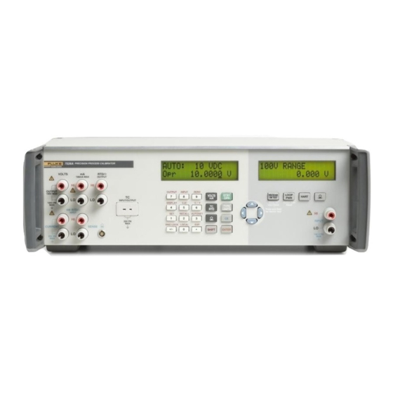
Introduction The Fluke 7526A Precision Process Calibrator (the “Product” or “Calibrator”) is an accurate, full-featured temperature, pressure, and DC calibrator. The Calibrator is meant for research and development, manufacturing, and calibration lab procedures. The Product operation is easy and you will quickly understand its operations and features. -
Page 10: Safety Information
7526A Getting Started Safety Information A Warning identifies conditions and procedures that are dangerous to the user; A Caution identifies conditions and procedures that could cause Product damage, equipment under test damage, or permanent loss of data. Warnings To prevent possible electrical shock, fire, or personal injury: •... -
Page 11: Unpack The Product
Precision Process Calibrator Unpack the Product Table 1 shows the symbols used on the Product and in this manual. Table 1. Symbols Symbol Definition Symbol Definition This product complies with the WEEE Directive (2002/96/EC) marking requirements. The affixed label indicates that you must not discard this electrical/electronic product in domestic household waste. -
Page 12: Standard Equipment
For more information about these accessories and their prices, contact your Fluke representative. • 5520A-525A Leads kit • Y7526A Rack Mount kit • Fluke 700 and 525A-P series pressure modules • MET/CAL with 7526A Function Select Code (FSC) • MET/CAL 7526A calibration procedure... -
Page 13: Product Description
This section is a general description of the Product. Front Panel Overview Figure 1 shows the layout of the front panel. Each of the three primary divisions is given in the subsequent sections. 7526A PRECISION PROCESS CALIBRATOR VOLTS RTD/ 100 mA MAX... -
Page 14: Primary Input/Output Terminals
7526A Getting Started Primary Input/Output Terminals Figure 2 shows the primary input/output terminals. 7526A PRECISION PROCESS CALIBRATOR VOLTS RTD/ 100 mA MAX OUTPUT OUTPUT 100 V MAX INPUT/OUTPUT 100V PK 4 W RTD/ INPUT 20 V PK CURRENT SENSE 20 V PK gwp002.eps... -
Page 15: Primary Input/Output Display And Controls
Precision Process Calibrator Product Description Primary Input/Output Display and Controls Figure 3 shows the primary input/output display and controls. OUTPUT INPUT ZERO VOLTS STBY DISPLAY C / F TYPE UNITS RECALL AUTOSET RNG LOCK LOCAL SHIFT ENTER gwp003.eps Item Description Display: A two-line, 16-character display that gives all visual user feedback for the primary output and input operations. - Page 16 7526A Getting Started Item Description Numeric and Secondary Function Keys: Output value data entry keys. Secondary function selection per the text printed above the numeric key. Push and then the numeric key to select the function. °C/°F Select Celsius or Fahrenheit units for RTD and Thermocouple ...
- Page 17 Precision Process Calibrator Product Description Function Keys For all but Thermocouple output modes, toggle between Standby and Operate modes. In Standby mode, changes to the output value in the display is not applied to the terminals until you select the Operate mode. In Operate mode, each change to the output value in the display is applied to the terminals immediately.
-
Page 18: Isolated Input Display, Controls, And Terminals
7526A Getting Started Isolated Input Display, Controls, and Terminals Figure 4 shows the isolated input display, controls, and terminals. LOOP VOLTS HART Press and Hold Switch Test for Switch Test Reset INPUT 100 V PK gwp004.eps Item Name Description A two-line, 16-character display gives all visual user feedback for the isolated input operations. -
Page 19: Rear Panel
Precision Process Calibrator Product Description Item Name Description Selects Pressure input mode. Subsequent pushes of this key cycle through the pressure units. Pressure input mode uses the pressure module connector on the primary input/output side. Each side can use pressure mode at the same time and can be set to show the same pressure measurement in different units if necessary. -
Page 20: Display Layouts
7526A Getting Started Display Layouts Figure 6 shows the primary voltage and current display. gwp006.eps Item Description Operation mode: Auto-range AUTO Range lock LOCK Remote operation Automatic stepping of preset setpoints SP # Current range and output mode ... - Page 21 Precision Process Calibrator Product Description Figure 7 shows the primary thermocouple and RTD display. gwp007.eps Item Description Output mode selection: RTD, TC, or rem for remote operation Input or output selection RTD or thermocouple type selection Output condition for RTD outputs: Standby, terminals inactive Stby Operating, terminals are active with output per the shown value...
- Page 22 7526A Getting Started Figure 8 shows the primary and isolated pressure display. gwp008.eps Item Description On the primary display, rem is shown to the left during remote operation. Input value Figure 8. Primary and Isolated Pressure Display Figure 9 shows the isolated voltage and current display.
-
Page 23: Error Messages
Precision Process Calibrator Getting Started Error Messages Table 2 shows the error messages that can appear on the displays. Table 2. Error Messages Message Description The numeric keypad value is larger than the range of the output mode OVER RANGE selected. -
Page 24: Specifications
7526A Getting Started Note If a correct power-up display does not occur in 30 seconds, turn off the power. Power on the unit after a few seconds. If the problem co n tin u e s, report the problem to Fluke immediately. -
Page 25: Dc Voltage Specifications, Output
Precision Process Calibrator Specifications DC Voltage Specifications, Output Absolute Uncertainty, tcal ±5°C, Stability ±(ppm of output +µV) Maximum Ranges Resolution 24 hours, ±1 °C Burden 90 Days 1 Year ±(ppm of output +μV) 0 mV to 100.000 mV 5 ppm + 2 μV 1 μV 10 mA 0 V to 1.00000 V... -
Page 26: Resistance Specifications, Output
7526A Getting Started Resistance Specifications, Output Absolute Uncertainty, tcal ±5 °C, ± Ohms Ranges Resolution Nominal Current 90 Days 1 Year 5 Ω to 400.000 Ω 0.012 0.015 0.001 Ω 1 to 3 mA 0.25 0.01 Ω 100 μA to 1 mA 5 kΩ... -
Page 27: Thermocouple Specification, Output And Input
Precision Process Calibrator Specifications Thermocouple Specification, Output and Input Absolute Uncertainty, tcal ±5 °C, ±(°C) Range (°C) TC Type Output/Input Minimum Maximum 90 days 1 Year 600 °C 800 °C 0.35 °C 0.35 °C 800 °C 1550 °C 0.28 °C 0.28 °C 1550 °C 1820 °C... -
Page 28: Rtd And Thermistor Specification, Output
7526A Getting Started Absolute Uncertainty, tcal ±5 °C, ±(°C) Range (°C) TC Type Output/Input Minimum Maximum 90 days 1 Year -250 °C -200 °C 0.34 °C 0.35 °C -200 °C -100 °C 0.14 °C 0.16 °C -100 °C 0 °C 0.09 °C... -
Page 29: Rtd And Thermistor Specification, Input
Precision Process Calibrator Specifications RTD and Thermistor Specification, Input Absolute Uncertainty, tcal ±5 °C, ±(°C) Range (°C) RTD Type Output/Input Minimum Maximum 90 Days 1 Year -200 °C -80 °C 0.012 °C 0.013 °C -80 °C 100 °C 0.018 °C 0.020 °C 100 °C 300 °C... -
Page 30: Pressure Measurement Specifications
7526A Getting Started Pressure Measurement Specifications The Calibrator can accept the Fluke 700 or 525A-P Series pressure modules. Pressure modules connect directly into the front panel Lemo connector with the Calibrator firmware auto-detecting the type and value of the module you connect.
Need help?
Do you have a question about the 7526A and is the answer not in the manual?
Questions and answers