
Related Manuals for Outback Power Systems FlexMax 60


Summary of Contents for Outback Power Systems FlexMax 60
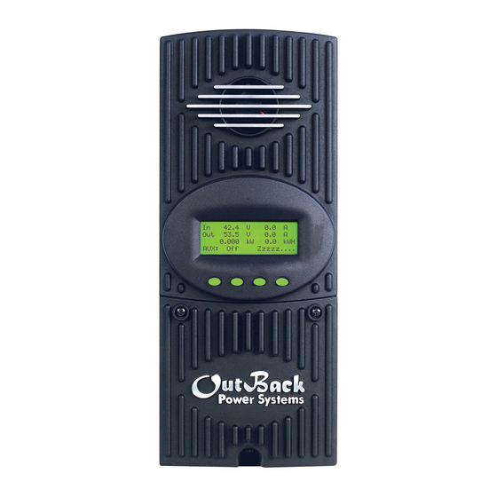
- Page 1 Maximum Power Point Tracking Charge Controller User’s Manual Installation and Programming...
- Page 2 Warranty Summary Dear OutBack Customer, Thank you for your purchase of OutBack products. We make every eff ort to assure our power conversion products will give you long and reliable service for your renewable energy system. As with any manufactured device, repairs might be needed due to damage, inappropriate use, or unintentional defect.
- Page 3 The OutBack Power Systems FLEXmax 80 and FLEXmax 60 Maximum Power Point Tracking Charge Controllers are ETL listed in North America to UL1741 (Inverters, Converters, Controllers, and Interconnection System Equipment for Use with Distributed Energy Resources). It is also in compliance with European Union standards EN 61000-6-1 and EN 61000-6-3 (see page 91).
-
Page 4: Table Of Contents
TABLE OF CONTENTS SCOPE ........................................5 INTRODUCTION ....................................5 INSTALLATION GUIDELINES AND SAFETY INSTRUCTIONS ..................6 Standards and Requirements ............................6 Battery Safety ....................................7 INSTALLING THE Charge Controller ON FLEXware ENCLOSURES ..............10 OPEN CIRCUIT VOLTAGE/WIRE AND DISCONNECT SIZING ................... 10 CHARGE CONTROLLER CONNECTIONS .......................... - Page 5 STANDARD vs. AUSTRALIAN DEFAULT SETTINGS .......................77 WIRE DISTANCE CHART FLEXMAX 80 ............................78 WIRE AND DISCONNECT SIZING FLEXMAX 80 ........................80 WIRE AND DISCONNECT SIZING FLEXMAX 60 ........................81 WIRING COMPARTMENT ..................................82 MULTI-STAGE BATTERY CHARGING .............................83 BATTERY TEMPERATURE COMPENSATED VOLTAGE SET POINT .................85 SUGGESTED BATTERY CHARGER SET POINTS ........................86...
-
Page 6: Scope
OutBack Power Systems MATE display (version 4.0.4 or greater). FIRMWARE This manual covers Charge Controller fi rmware version 001.009.001 *For simplicity’s sake, both the FLEXmax 60 and FLEXmax 80 will be referred to in this manual as “Charge Controller or by the abbreviation “CC. ”... -
Page 7: Installation Guidelines And Safety Instructions
OUTBACK CHARGE CONTROLLER INSTALLATION GUIDELINES AND SAFETY INSTRUCTIONS This product is intended to be installed as part of a permanently grounded electrical system as shown in the system confi guration sections (see pages 12-15) of this manual. The following important restrictions apply unless superseded by local or national codes: •... -
Page 8: Battery Safety
WARNING - WORKING IN THE VICINITY OF A LEAD ACID BATTERY IS DANGEROUS. BATTERIES GENERATE EXPLOSIVE GASES DURING NORMAL OPERATION. Design the battery enclosure to prevent accumulation and concentration of hydrogen gas in “pockets” at the top of the enclosure. Vent the battery compartment from the highest point to the outside. A sloped lid can also be used to direct the fl ow of hydrogen to the vent opening. - Page 10 1. Installing the Charge Controller The Charge Controller is designed to attach directly to OutBack’s FLEXware 500 DC and FLEXware 1000 DC enclosures (FLEXware 500 shown) or attach to its own charge control brackets (FW-CCB, FW-CCB2, and FW-CCB2T). NOTE: Install the Charge Controller in an upright position out of direct sunlight.
-
Page 11: Installing The Charge Controller On Flexware Enclosures
64 amps or less under STC (Standard Test Conditions). FLEXmax 60 • The output current limit of the FLEXmax 60 is 60 amps • Use a minimum of 6 AWG (13.3 mm wire for the output between the FLEXmax 60 and the battery bus bar conductors •... - Page 12 NOTE: Input conductors and circuit breakers must be rated at 1.56 times the short-circuit current of the PV array. OutBack 100% duty continuous breakers only need to be rated at 1.25 times the short- circuit current. • Please see the wire Distance Chart and complete Wire and Disconnect Sizing on pages 78-81 for other suitable conductor/wire sizing.
-
Page 13: Charge Controller Connections
3. Charge Controller Wiring Connections Figure 1 Charge Controller wiring compartment Use up to 2 AWG (33.6 mm ) wire and torque to 35-inch pounds at PV+ PV- BAT- BAT+ terminals. Wire Lugs MATE/HUB RJ45 jack Chassis/Equipment Ground Lug Battery Remote Temp Sensor (RTS) RJ11 jack Programmable AUX Output Jack... - Page 14 Figure 2 Single Charge Controller wiring diagram with 24 volt PV array...
- Page 15 Figure 3 Charge Controller Wiring Diagram with an FX, HUB 4, and an RTS...
- Page 16 Figure 4 Charge Controller with PV array ground fault protection wiring digram.
-
Page 17: How To Read The Charge Controller Screen Diagrams
How to Read the Charge Controller Screen Diagrams Soft keys: (#1) (#2) (#3) (#4) Solid black indicates key is to be pressed: Down arrow will lead to the next screen: Up arrow points to one or more keys that will change a value: The keys correspond to any text immediately above them. -
Page 18: Powering Up
4. Powering Up The Charge Controller power-up sequence fi rst activates the unit and the SELECT VERSION screen (to determine a choice of English, Espanola, or Australian settings). A SYSTEM VOLTAGE screen soon follows. However, when it auto-detects the system’s battery voltage, in some instances the Charge Controller might not refl ect the correct system voltage (e.g., if a 36VDC system falls to a voltage range that could be misread as a 24VDC system). - Page 19 Select Version The Charge Controller screens are off ered in English Elija la Version (standard screens) and Spanish. For Australian users, some English of the charging values are of diff erent voltages and the NEXT ENTER ENTRA SEL Charge Controller accommodates these. By pressing the <NEXT>...
- Page 20 Are you sure? Press the <YES> soft key to confi rm your choice or <NO> to return to the SELECT VERSION screen. English The Charge Controller auto detects the system’s battery voltage. To confi rm this voltage, press the <ENTER> soft System Voltage Screen key.
-
Page 21: Status Screen
5. Status Screen The STATUS Screen displays system information. See page 63 for detailed information of the diff erent Operational Modes. The optional OutBack MATE displays CC (Charge Controller) STATUS screens for convenient distant viewing from the installation location of the Charge Controller. Please see pages 66-68 to view the Charge Controller screens displayed on the MATE. -
Page 22: End Of Day Summary Screen
6. End of Day Summary Screen The End of Day summary screen appears after one hour of continuous sleeping. This screen can be opened anytime by pressing the second soft key while in the STATUS screen, providing a summary up to that point. -
Page 23: Accessing The Main Menu
8. Accessing the MAIN Menu The MAIN Menu allows the user to adjust and calibrate the Charge Controller for maximum perfor- mance. From the STATUS screen, press the fi rst soft key on the left to open the MAIN Menu screen. Press the <GO>... -
Page 24: Charger Setup
7. Charger Set-Up This screen allows changes to the Charge Controller’s recharging voltage set points—Current Limit, Absorb and Float (for an explanation of battery charging, see pages 83-84): • The presently selected numerical value will have an arrow “ ” to the left of it. •... -
Page 25: Aux Mode And Its Functions
8. AUX Mode and Its Functions The AUX is a secondary control circuit—essentially, a small power supply that provides a 12VDC (up to 200 milliamps) output current. It is either active (12VDC on) or inactive (0VDC). Most AUX modes or functions are designed for specialized applications and are infrequently used. -
Page 26: Aux Mode Path
AUX MODE Menu Path Charger Light Charger Light AUX MODE Misc Advance Misc Advance Vent Fan Logging Stats Logging Stats Output: Off EXIT EXIT EXIT NEXT SET MODE PASSWORD AUX MODE ***150*** Vent Fan Output: Off ENTER EXIT NEXT SET MODE To access the AUX Output Menu: •... -
Page 27: Aux Modes Described
AUX modes in order of appearance on the Charge Controller display: • Vent Fan • PV Trigger • Error Output • Night Light • Float • Diversion Relay • Diversion Solid State • Low Battery Disconnect • Remote NOTE: All AUX functions can be manually activated in On, Off , or Auto mode. In Auto mode, the function will automatically activate when a user-determined value is met and deactivate or shut down when other conditions described here, such as a certain amount of time passing, occur. -
Page 28: Programming The Aux Modes
9. Programming the AUX MODES VENT FAN AUX MODE Press the <MODE> soft key to manually activate Vent Fan or deactivate (On or Off ) the Vent Fan; if set to Auto, Output: Off the Vent Fan will turn on when a user-determined voltage is met. -
Page 29: Pv Trigger
AUX MODE Press the <EXIT> soft key return to the main Vent Vent Fan Fan screen. EXIT VOLT AUX MODE Press the <NEXT> sot key to view the PV Trigger Vent Fan screen Output: Off EXIT NEXT SET MODE PV TRIGGER AUX MODE When the PV input exceeds the user-determined PV Trigger... - Page 30 AUX MODE PV Trigger Press the <SET> soft key to open the PV Trigger’ s TIME Output: On and VOLT(age) set menus. EXIT NEXT SET MODE AUX MODE PV Trigger To adjust the voltage, press the <VOLT> soft key. EXIT TIME VOLT PV VOLTS Adjust the voltage within a range of 20V-145V by...
- Page 31 Press the < - > or < + > soft key to adjust the Hold Hold Time Sec Time, then press the <BACK> soft key to return to the 01.1 PV Trigger screen. In this example, the AUX MODE will remain active for 1.1 seconds after the PV voltage is BACK below the PV Trigger voltage before deactivating the PV...
-
Page 32: Error Output
ERROR OUTPUT The ERROR OUTPUT default state is On, meaning 12 AUX MODE VDC is present at the AUX terminal. If the Charge ERROR OUTPUT Controller has not charged the batteries for 26 Output: On hours or more continuously, the inaudible ERROR EXIT NEXT SET MODE OUTPUT goes into an Off state. -
Page 33: Night Light
NIGHT LIGHT AUX MODE The Night Light illuminates a user provided low-wattage Night Light light when the PV voltage falls below a user-determined Output: Off voltage. Off is the default value. Press the <MODE> soft EXIT NEXT SET MODE Auto key to change the Night Light MODE (Off , On, or Auto). - Page 34 Use the < - > and < + > soft keys to adjust the time Night Light required for the PV input voltage to be above the thresh- Off Hysteresis Time Minutes old voltage before the Night Light is disabled. Press the <BACK>...
-
Page 35: Float
AUX MODE Night Light Press the <EXIT> soft key to return to the Night Light AUX mode. EXIT HYST TIME VOLT AUX MODE Night Light Press the <NEXT> soft key ro view the AUX Float Output: Off Auto screen. EXIT NEXT SET MODE FLOAT AUX MODE... - Page 36 AUX MODE Press the <TIME> soft key to advance to the Time Diversion: Relay screen which allows the user to adjust the minimum time the AUX MODE is active after the battery voltage EXIT TIME VOLT falls below the Hysteresis voltage. Hold Time shows how long the AUX MODE stays active Hold Delay...
-
Page 37: Diversion: Solid State
AUX MODE Diversion: Relay Press the <EXIT> soft key. EXIT TIME VOLT AUX MODE Diversion: Relay If a Solid State Relay is used, press the <NEXT> soft key to Output: Off access the Diversion Solid St screen. EXIT NEXT SET MODE To adjust the time and voltage when a solid state relay is AUX MODE used, press the <TIME>... - Page 38 Figure 5 Diversion Load and AUX Wiring Set-Up Illustrated...
-
Page 39: Low Battery Disconnect
LOW BATTERY DISCONNECT When the battery voltage falls below the disconnect AUX MODE volts, the AUX connected loads only are disconnected; Low Batt Disconnect the AUX connected loads only are connected when Output: On the battery voltage rises above the reconnect volts. EXIT NEXT SET MODE To adjust these set points, press the <TIME>... - Page 40 AUX MODE In the Low Batt Disconnect screen, press the <VOLT> soft Low Batt Disconnect key to adjust the battery voltage disconnects set point. EXIT TIME VOLT DISCONNECT VOLTS Press either the < - > or the < + > soft key to adjust the <...
-
Page 41: Remote
AUX MODE Low Batt Disconnect Press the <EXIT> soft key. EXIT TIME VOLT AUX MODE Low Batt Disconnect Press the <NEXT> soft key to view the Remote screen. Output: Off EXIT NEXT SET MODE REMOTE AUX MODE Remote In Remote AUX MODE, the OutBack MATE can Output: Off control the Charge Controller’s AUX MODE. -
Page 42: Backlight
10. Backlight Auto (default) leaves backlight and soft keys on for BACKLIGHT CONTROL up to nine minutes whenever any soft key is pressed Auto Time 2 Minutes (pressing any soft key when the LCD is not lighted Auto Auto does not change any settings). Minutes are adjustable using the <... - Page 43 BATTERY EQUALIZE Press either the < –EQV> or <+EQV > soft key to change Volts the EQ voltage, following your battery manufacturer’s 15.0 recommendations. Note that the factory default EQ voltage is set low, the same as the factory default Absorb EXIT NEXT -EQV +EQV voltage.
- Page 44 AUTO MODE Use the <-DAY> and <+DAY> soft keys to preset the COUNT EQ INTERVAL interval day to initiate an automatic equalization cycle. The EQ INTERVAL displays the number of days in the interval between cycles and COUNT displays how many EXIT -DAY +DAY days of the interval have passed.
-
Page 45: Misc-Miscellaneous
12. MISC—Miscellaneous The MISCELLANEOUS screens display extra settings and technical information, some of which is useful for OutBack Power Systems Technical Services. The Grid Tie (GT) value is sent Each MPPT operation is This is the duty cycle of from G-series inverter through the a state. - Page 46 GT State PWM% ChgT 50.0 Press the <NEXT> soft key to view the FORCE FLOAT, or BULK screen. EXIT NEXT RSTRT Pressing the <FLOAT> or <BULK> soft key forces the Charge Controller to that specifi c recharging cycle and returns to the STATUS screen. Forcing a FLOAT or BULK FORCE recharge will end an EQ cycle.
-
Page 47: Advanced
13. Advanced The ADVANCED MENU allows fi ne-tuning of the Charge Controller operations including Snooze periods and Maximum Power Point limits. In order of appearance, the following modes occur in the ADVANCED Menu selections: • Snooze Mode • Wakeup • MPPT Mode • Park Mpp • Mpp Range Limit % Voc •... -
Page 48: Wakeup Mode
Wakeup Mode selects how often the Charge Controller ADVANCED MENU does a “Wakeup” during “Snoozing” periods. Since Wakeup Mode environmental conditions impact the open circuit 1.5V 05m voltage (Voc) of an array, a user selectable Voc rise in value will allow the controller to “wakeup” sooner or later EXIT NEXT +VOC +Min based on the last measured Voc value. -
Page 49: Park Mpp
ADVANCED MENU ADVANCED MENU Park Mpp Park Mpp 77 % Voc Watts 0251 77 % Voc EXIT NEXT -% +% EXIT NEXT -% +% As the user changes the %Voc value using the <-%> and <+%> soft keys, the displayed Watts value also changes. -
Page 50: Charging Related Screens
14. Charging-Related Screens In the Absorb Time Limits screen, the user can set the ADVANCED MENU duration the Charge Controller stays in the Absorb Absorb Time Limits recharge cycle. 01.0 hours • Absorb Time is adjustable from 0 to 24 hours (consult EXIT NEXT your battery manufacturer’s recommendations). -
Page 51: Rebulk Voltage
Charge Controller Multi-Stage Battery Charging Figure 6 NOTE: In BULK, the Charge Controller will charge as long as necessary to complete the cycle, regardless of the timer’s set points An Absorb charge cycle normally ends when a battery ADVANCED MENU voltage is maintained at the Absorb set point for the Absorb End Amps user-determined time period. -
Page 52: Vbatt Calibration
A quality calibrated voltmeter will provide even more ADVANCED MENU accurate Charge Controller battery readings if an undesir- Vbatt Calibration able voltage drop occurs. When measuring battery volt- 14.1 V 0.0 V age, ensure a good connection is made to the four wire lugs. -
Page 53: Auto Restart
ADVANCED MENU RTS Compensation Press the <NEXT> soft key to view the Auto Restart A 14.4 V F 13.8V screen. EXIT NEXT LIMIT SET AUTO RESTART ADVANCED MENU Pressing the fourth soft key selects among the three Auto ReStart Charge Controller Auto ReStart modes: 0 (default), 1, and MODE 2 2. -
Page 54: Aux Polarity
ADVANCED MENU Auto ReStart From the Auto Restart MODE 2 screen, press the <NEXT> MODE 2 soft key to view the Aux Polarity screen. EXIT NEXT MODE When the AUX function is ON, 12 volts is present at the AUX terminal; when it’s OFF, 0 volts are present ADVANCED MENU at the terminal. - Page 55 Are you sure? Pressing the <YES> soft key brings up a Reset to Defaults Reset to Defaults screen momentarily before returning to the Reset to Defaults? screen ADVANCED MENU Reset to Defaults? Press the <EXIT> key twice to return to the MAIN Menu screen.
-
Page 56: (Data) Logging
15. Logging A user can clear either the daily or accumulated statistics Today 0000Ah 00.0 KWH of the Charge Controller by pressing the second button 011Vp 00.0Ap 0.00kWp from the left in this screen. This will bring up the CLEAR MAX 14.7V ABS 01:00 LOG screen. -
Page 57: Stats
16. Stats Charger Light From the MAIN Menu, press the < > soft key to move Misc Advanced the arrow next to the Stats function and then press the Logging Stats <GO> soft key EXIT The STATS screen displays additional voltage and time information. -
Page 58: Secondary Stats Screen
Secondary STATS screen Total 0000 The Secondary Stats screen shows the total accumulated Total 000.0 DC and AC kilowatt hours and kiloamp hours of the Charge Controller. BACK DCkWH Pressing the <DCkWH> soft key switches the screen between DC kilowatt hours and AC kilowatt hours •... -
Page 59: Micro-Hydro, Wind Turbine, And Fuel Cell Applications
The Charge Controller is designed to work with solar arrays. Although it will work with micro-hydro turbines and fuel cell, OutBack Power Systems can only off er limited technical support for these applications because there is too much variance in micro-hydro and fuel cell generator specifi cations. -
Page 60: Advanced Menu (Micro-Hydro)
18. Advanced Menu (Micro-Hydro and Fuel Cell Applications) Mpp Range Limit % (Auto Track Mode only) The Charge Controller searches for the MPP voltage by tracking the input voltage up to one half (default) of the Voc, which is based on values appropriate for a solar array. Micro-hydro and fuel cell systems can require a broader range, normally on the lower end. -
Page 61: Charge Controller Abbreviated Menu Map
19. Abbreviated Menu Map Much of the Charge Controller activity takes place around the MAIN screen. From this screen, the user can access other screens to both observe system activiy and make adjustments to certain critical func- tions. Charger Aux Light The Light feature con- Misc Advanced trols the backlighing of... -
Page 62: Application Notes
20. Application Notes OutBack Power System GTFX/GVFX Grid-tie settings In a GTFX/GVFX Series Inverter/Charger, Charge Controller, HUB, and MATE installation set the Charge Controller to GT mode in the ADVANCED MENU. GT mode allows the GTFX/GVFX to manage the Charge Controller fl oat setting ensuring the Charge Controller is always keeping the battery above the sell voltage of the GTFX/GVFX. -
Page 63: Charge Controller Efficiency Vs. Input Power Graph
21. Charge Controller EFFICIENCY vs. INPUT POWER GRAPH Charge Controller Effi ciency vs Input Power INPUT= 17V, 34V, 51V, 68V, 85V, 100 V OUTPUT = 12V Nominal Figure 7 12V Battery System Effi ciency Curve Charge Controller Effi ciency vs Input Power INPUT= 34V, 51V, 68V, 85V, 100 V OUTPUT = 24V Nominal Figure 8 24V Battery System Effi ciency Curve... -
Page 64: Understanding The Various Operational Modes
22. Understanding the Various Operational Modes The Charge Controller modes of operation will change occasionally during the day based on the PV array output and the battery system state of charge. The Charge Controller operating modes are displayed at the bottom right hand corner of the STATUS screen. Absorbing The Charge Controller is in the Absorb (constant voltage) charge stage, regulating the battery voltage at the Absorb voltage set point (modifi ed by battery temperature compensation if installed). - Page 65 GT Mode In a system with an OutBack FX Grid-Tie Series Inverter(s), HUB and MATE, the Charge Controller will display GT Mode if and only if the inverter is in Sell mode and the Charge Controller is in Bulk (MPPT BULK) or Float (MPPT FLOAT) cycle. This is also a good indicator for establishing proper Grid-Tie mode communication between the FX G-Series Inverter(s) and Charge Controller.
- Page 66 Sleeping The PV voltage is two volts less than the battery voltage. This may also appear during the day when the Charge Controller is transitioning between certain states, or due to other conditions. SysError (Very rare) System Error indicates an internal non-volatile memory error. The unit will stop operating when this message is displayed.
-
Page 67: Mate-Displayed Charge Controller Status Mode Screens
23. MATE-Displayed Charge Controller Screens Status Mode Screens The Charge Controller STATUS MODE Screens displayed on the optional OutBack MATE (Rev 4.0.4 or greater) include MODE, METER, and SET (SETPOINT). In STATUS Mode, these functions can be viewed by the MATE, but not changed. Please see the MATE Installation and User Manual for more information. MAIN------------------------------ STATUS--------------------------- STATUS/CC/PAGE 1-----------... -
Page 68: Mate-Displayed Charge Controller Status Meter Screens
MATE-Displayed Charge Controller Status Meter Screens mode: Silent STATUS/CC/METER--------P02 STATUS/CC/METER-----P02 10.2 vdc 0 adc charger charger 0.0 kwh out: 13.4 vdc 0 adc watts kwhrs DOWN STATUS PORT DOWN PORT DOWN PORT STATUS/CC/METER-------P02 STATUS/CC/METER---------P02 STATUS/CC/METER--------P02 charger +000 adc battery 13.5 vdc panel 10.2 vdc amps dc... -
Page 69: Mate-Displayed Charge Controller Status Setp(Oint) Screens
MATE-Displayed Charge Controller STATUS SETPT (SET POINT) Screen STATUS/CC/SETPT---------P00 STATUS/CC/SETPT---------P00 Absorb 28.8 VDC Float 27.2 VDC DOWN STATUS PORT DOWN PORT STATUS/CC/METER------ Press the fi rst two soft keys simultaneously end of setpoint menu to return to the MAIN Menu. TOP STATUS CC SETP(OINT) Screens •... -
Page 70: Advanced Menu
24. Charge Controller Advanced Menu ADV/CC/ADVANCED--------P01 ADV/CC/ADVANCED--------P01 ADV/CC/ADVANCED--------P01 snooze now wakeup mode wakeup mode < 0.6 amp time 5 minutes VOC change 1.5 V DOWN PORT DOWN PORT DOWN PORT ADV/CC/ADVANCED--------P01 ADV/CC/ADVANCED--------P01 ADV/CC/ADVANCED--------P01 grid tie mode MPPT mode park MPP 77.0 non GT auto track DOWN... -
Page 71: Eq Screens
Charge Controller EQ Screens ADV/CC/EQ-----------------P01 ADV/CC/EQ-----------------P01 ADV/CC/EQ-----------------P01 auto eq interval eq voltage 14.4 vdc eq time 1 hrs 0 days DOWN PORT DOWN PORT DOWN PORT ADV/CC/EQ---------------------- end of CC eq menu MAIN Charge Controller AUX Screens ADV/CC/AUX/--------------P01 ADV/CC/AUX/MODE--------P01 ADV/CC/AUX/----------------- aux output Night Light end of menu... -
Page 72: Abbreviated Menu
25. ABBREVIATED CHARGER SET-UP Current Limit 80.0 A OutBack AUX MODE COUNT EQ INTERVAL Absorbing 14.4 V Power Diversion: Solid St Systems Float 13.8 V Output: Off Charge Controller EXIT NEXT SET MODE EXIT EXIT -DAY +DAY PRESS MODE KEY FOR PUSH THREE TIMES PUSH TWICE OFF, ON,and AUTO... - Page 73 ADVANCED MENU ADVANCED MENU REVISION Park Mpp Reset to Defaults? 77% VOC 001.008.009 EXIT NEXT +VOC +Min EXIT NEXT RESET PUSH TWICE EXTENDED PLAYMODE ADVANCED MENU Charger Light Mpp Range Limit %Voc Misc Advanced Logging Stats Min Max Charger Aux Light EXIT EXIT...
-
Page 74: Troubleshooting Guide
26. Troubleshooting Guide Be sure to check out the OutBack customer and user forum at www.outbackpower. Charge Controller does not boot/power-up (blank LCD) com/forum/ for more Charge Controller information. • Check the battery connection and polarity. - Reverse polarity or an improper connection will cause power-up issues. •... - Page 75 • Are the batteries charged? Is the Charge Controller in the Absorbing or Float stage? If either case is true, the Charge Controller will produce enough power to regulate the voltage at the ABSORB or FLOAT set point voltage, therefore, requiring less power in these modes. •...
- Page 76 Charge Controller Internal Fan • The internal fan will only run when the internal temperature has reached approximately 112°F. The fan will continue running until the internal temperature is less than 104°F. Charge Controller is beeping • When the Charge Controller is in Extended Play mode, the array is very hot, and the MPP is close to the battery voltage, or the nominal PV voltage is higher than the nominal battery voltage, beeping can occur.
-
Page 77: Typical Array Sizing Guide
27. Typical Array Sizing Guide Below is a list of recommended array sizing for the Charge Controller for various nominal voltage batteries: Nominal Battery Voltage Recommended Array Size (in watts, Standard Test Conditions) FLEXmax 80 FLEXmax 60 1250W 800W 2500W 1600W 3750W 2400W... -
Page 78: Standard Vs. Australian Default Settings
28. STANDARD vs. AUSTRALIAN DEFAULT SETTINGS The Australian version Charge Controller has a few default settings that diff er from the Standard ver- sion default settings. However, there are no diff erences in performance and effi ciency between the two versions. The Standard and Australian version can be identifi ed as follows: OutBack OutBack Power... -
Page 79: Wire Distance Chart Flexmax 80
To meet NEC compliance (North America), the largest PV array that can be connected to a FLEXmax 80 must have a rated short-circuit current of 64 amps or less and 48 amps or less for a FLEXmax 60. The following charts show the maximum distance of various gauge two-conductor copper wire from the PV array to the Charge Controller with a 1.5% maximum voltage drop. - Page 80 48V PV ARRAY (64v Vmp) #1/0 #2/0 #3/0 #4/0 WIRE GAUGE 60V PV ARRAY (80v Vmp) WIRE GAUGE #1/0 #2/0 #3/0 #4/0 72V PV ARRAY (96v Vmp) WIRE GAUGE #1/0 #2/0 #3/0 #4/0 1184 METRIC NOTE: Numbers in bold might not meet NEC requirements #8…8.37mm #6…13.30mm #4…21.15mm...
-
Page 81: Wire And Disconnect Sizing Flexmax 80
30. WIRE AND DISCONNECT SIZING FLEXmax 80 The Charge Controller is a buck type converter with the following properties: • 80 amp DC output current limit (default setting) • Listed to operate continuously at 80 amps (40°C/104° F) With an 80 amp Charge Controller output current limit and PV array output higher than 80 amps off ers little, if any, current boosting or Maximum Power Point Tracking advantage;... -
Page 82: Wire And Disconnect Sizing Flexmax 60
WIRE AND DISCONNECT SIZING FLEXmax60 The MX60 has a 60 amp current output limit (default) and is listed to operate continuously at 60 amps depending on the nominal PV array voltage and the nominal battery voltage. There is no 80% de-rating as required by the NEC* for fuses, conductors, and most circuit breakers. -
Page 83: Wiring Compartment
31. WIRING COMPARTMENT The wiring terminals and compartment of the Charge Controller Charge Controller are fully compli- ant with all NEC and UL requirements. The following summary is specifi c for North American applications where NEC and UL standards govern installations. Recommended Conductor and Breaker Sizes for the Charge Controller Output Rating at 80 amps If the output current of the Charge Controller is expected to reach the maximum output level of 80... -
Page 84: Multi-Stage Battery Charging
32. Charge Controller MULTI-STAGE BATTERY CHARGING The Charge Controller charge controller is a sophisticated, multi-stage battery charger that uses several regulation stages to allow fast recharging of the battery system while ensuring a long battery life. This process can be used with both sealed and non-sealed batteries. The Charge Controller has a preset recharging voltage set points (Absorb &... - Page 85 BULK cycle provides the maximum power to the battery –the voltage increases while recharging. A Bulk cycle is automatically initiated when the battery voltage is below the Absorb and Float* recharge voltage set points. The Bulk cycle will continue until the Absorb voltage set point is achieved. MPPT Bulk is displayed on the screen.
-
Page 86: Battery Temperature Compensated Voltage Set Point
33. BATTERY TEMPERATURE COMPENSATED VOLTAGE SET POINT The temperature of a battery has an impact on the recharging process—in higher ambient temperatures, the regulation set points (Absorb and Float) need to be reduced to prevent overcharging of the batteries. In lower ambient temperature conditions, the voltage regulation set points need to be increased to ensure complete recharging of the batteries. -
Page 87: Suggested Battery Charger Set Points
34. SUGGESTED BATTERY CHARGER SET POINTS The battery manufacturer should provide you with specifi c instructions on the following maintenance and voltage set point limits for the specifi c batteries. The following information can be used when the manufacturer’s information is not available. SEALED LEAD ACID –... -
Page 88: Calling The Factory For Assistance
Five years parts and labor Dimensions FLEXmax 80–16.25”H x 5.75”W x 4”D Boxed–21”H x 10.5”W x 9.75”D FLEXmax 60–13.5”H x 5.75” W x 4” D Boxed–18” H x 11” W x 8” D Weight FLEXmax 80–12.20 lbs; Boxed–15.75 lbs FLEXmax 60–11.6 lbs; Boxes–14 lbs... -
Page 89: Warranty Information
FIVE YEAR LIMITED WARRANTY INFORMATION FLEXmax Products OutBack Power Systems, Inc. (“OutBack”) provides a fi ve year (5) limited warranty (“Warranty”) against defects in materials and workmanship for its FLEXmax products (“Products”) if installed in fi xed location applications. For this Warranty to be valid, the Product purchaser must complete and submit the applicable Product registration card within ninety (90) days of the eligible Product’s fi rst retail sale. - Page 90 To request warranty service, you must contact OutBack Technical Services at (360) 435-6030 or support@outbackpower.com within the eff ective warranty period. If warranty service is required, OutBack will issue a Return Material Authorization (RMA) number. A request for an RMA number requires all of the following information: 1.
-
Page 91: Product Registration And Optional Extended Warranty
*Extended Warranty OutBack Power Systems off ers an optional fi ve(5) year extension to the standard fi ve(5) year Limited Warranty in North America for the Charge Controller product. To request a 5-year Limited Warranty extension for a total eff ective warranty coverage period of ten(10) years;... -
Page 92: Eu Declaration Of Conformity
EN 61000-6-3 (2001) EN 61000-6-1 (2001) EN 60335-1 Battery Chargers EN 60335-2-29Battery Chargers All associated technical fi les are located in the Engineering Department at OutBack Power Systems Inc., Arlington, Washington, USA. As the manufacturer, we declare under our sole responsibility that the above-mentioned product complies with the above-named directives. -
Page 93: Owner's System Information
OWNER’S SYSTEM INFORMATION Date of Purchase: __________________________________________________________________ Vendor: __________________________________________________________________________ Date of Installation: _________________________________________________________________ Installer: _________________________________________________________________________ Installer Contact Information: _________________________________________________________ Charge Controller Serial Number: ______________________________________________________ Battery Voltage: ____________________________________________________________________ PV Voltage: _______________________________________________________________________ PV Module Type and Manufacturer: ____________________________________________________ Array Wattage: _____________________________________________________________________ NOTES: __________________________________________________________________________ _________________________________________________________________________________... - Page 94 Corporate Offi ce European Sales Offi ce 19009 62nd Avenue NE C/ Castelló, 17 Arlington, WA USA 08830 - Sant Boi de Llobregat Phone: (+1) 360-435-6030 BARCELONA, España Phone: +34.93.654.9568 www.outbackpower.com 900-0009-01-00 REV A...
Need help?
Do you have a question about the FlexMax 60 and is the answer not in the manual?
Questions and answers