Outback Power Systems MX60 Installation And User Manual
Pv mppt charge controller
Hide thumbs
Also See for MX60:
- Installation, programming, and user's manual (92 pages) ,
- Quick manual (12 pages)
Advertisement
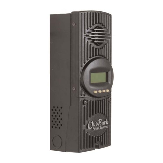
MX60
PV MPPT Charge Controller
I
N
S
T
A
L
L
A
T
I
O
N
A
N
D
U
S
E
R
'
S
M
A
N
U
A
L
I
N
S
T
A
L
L
A
T
I
O
N
A
N
D
U
S
E
R
'
S
M
A
N
U
A
L
Please read this entire manual prior to installing and using the MX60.
OutBack Power Systems, Inc 19009 62nd Ave NE Arlington WA 98223
360-435-6030
900-0028-1 Rev.-
Advertisement
Table of Contents

Related Manuals for Outback Power Systems MX60


Summary of Contents for Outback Power Systems MX60
- Page 1 MX60 PV MPPT Charge Controller ’ ’ Please read this entire manual prior to installing and using the MX60. OutBack Power Systems, Inc 19009 62nd Ave NE Arlington WA 98223 360-435-6030 900-0028-1 Rev.-...
-
Page 2: Important Safety Instructions
Rated for up to 60 amps of DC output current, your MX60 can be used with battery systems from 12 to 60 vdc with PV open circuit voltage as high as 125 vdc. The MX60's setpoints are fully adjustable to allow use with virtually any battery type, chemistry and charging profile. -
Page 3: Installation
Under the wiring compartment cover are holes through the mounting feet for attachment to the CCB . There is also a mounting tab at the top of the MX60. When mounted to the OutBack CCB the left side knockout will line up with knockouts in the PSDC. - Page 4 Mounting the MX60 Up to three MX60's can also be mounted on top of a PSDC. Below is a view from the top of the PSDC enclosure. The MX60 will mount using 1" TSC threaded nipples to the 2" spacings. One knockout is provided and one pilot hole for the second hole.
-
Page 5: Surge Protection
In terms of NEC compliance and the 60-amp output rating on the MX60, the largest PV array that can be connected to the MX60 should have a rated short-circuit current of 48 amps. This will meet NEC requirements and allow the MX60 to perform maximum power-point tracking functions. - Page 6 To the left of the PV+ terminal is an RJ45 jack marked MATE. The MATE is the OutBack remote display panel. Most of the status that is available on the MX60 is available at the Mate as well. Some triggered events can be accomplished at the MATE also.
-
Page 7: Operation Status
Operation Status The MX60 Charge Controller has a 4 line, 80 character LCD display and four “soft key” buttons to allow the user to adjust battery charging parameters and access other information. The MX60 has an adjustment screen lockout that requires an access code to make any changes. -
Page 8: Modes Of Operation
PV IV (Amps / Volts) sweep. At the end of the wake up period the MX60 closes its relays and produces power. At dusk and dawn this will happen many times until there is not enough power from the PV array to keep going. - Page 9 It can also directly drive a small piezo buzzer or a small 12V LED indi- cator. Manual Mode: You can turn on and off the AUX output manually from the MX60 keypad. Disabled: The AUX output terminals have no output.
- Page 10 Backlight Control: The back lighting of the LCD screen and the buttons consumes about ¾ watt. The user can control backlight options using the setup screen shown in Figure 9. Depending on your energy production, you may elect to leave the lighting off or on. There is also a third option called Auto. Tapping any key quickly while in Auto mode will turn the lights on for 30 seconds.
- Page 11 Voc: This is the open circuit voltage of the PV panels measured at the last wakeup cycle. State: The MX60 has thousands of lines of code. Each operation is called a State. This number is useful for troubleshooting. PWM%: This is the duty cycle of the buck converter.
- Page 12 (ChgT in Figure 13), the MX60 will switch to float charge mode. This is an optional setpoint and is not required to be adjusted in most installations.
-
Page 13: Specifications
Specifications: Output Current Rating: 60 Amps Nominal Battery Voltage: 12, 24, 36, 48 or 60VDC (programmable) PV open circuit voltage: 120VDC Maximum Standby power consumption: Less than 1 watt typical Charging regulation methods: Five stage: Bulk, Absorption, Float, Silent, Equalization Voltage regulation setpoints: 13-80VDC Equalization Voltage:... - Page 14 OutBack Power Systems’ liability for any defective product or any part thereof shall be limited to the repair or replace- ment of the product, at OutBack Power Systems’ discretion. OutBack Power Systems does not warrant or guarantee the workmanship performed by any person or firm installing its products.
- Page 15 REGISTER YOUR PRODUCTS Your purchase of an OutBack Power Systems product is an important investment. Registering your products will help us maintain the standard of excellence you expect from us in terms of performance, quality and reliability. Please take a moment to register and provide us with some important information.
- Page 16 FROM Postage Required OutBack Power Systems, Inc 19009 62nd Ave NE Arlington WA 98223...
Need help?
Do you have a question about the MX60 and is the answer not in the manual?
Questions and answers