Table of Contents
Advertisement
Quick Links
Highlighted copy for customers of
Miller Solar
805-438-5600
william@millersolar.com
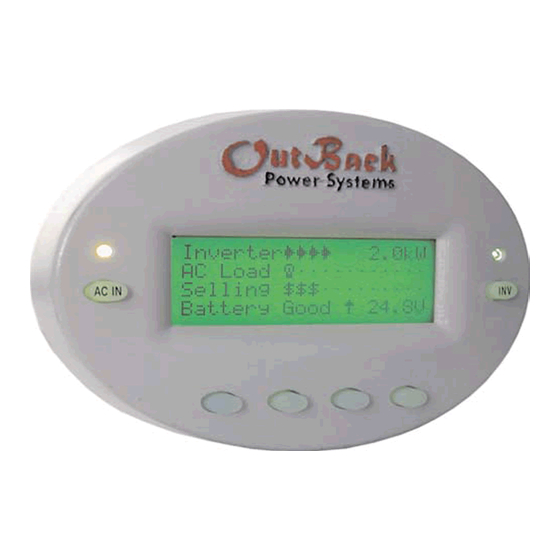
OutBack Power Systems
MATE
System Controller and Display
NOTE! This manual does not cover all functions of the MATE Controller. Rather, it is intended as a training aid for
new customers. It does cover all necessary functions for normal operation of this unit. The most important
information is highlighted in yellow. For complete function set, see the original manual.
Installation and User Manual for the OutBack MATE and MATE2
Please check our website at
www.outbackpower.com
for the latest product information
Copyright 2003 © OutBack Power Systems, Inc.
User Manual
MATE System Controller and Display
nd
19009 62
Ave NE, Arlington WA 98223 USA
Page 1
Tel 360 435 6030
Fax 360 435 6019
Rev 2.30 03/31/04
Advertisement
Table of Contents

Related Manuals for Outback Power Systems MATE


Summary of Contents for Outback Power Systems MATE
- Page 1 System Controller and Display NOTE! This manual does not cover all functions of the MATE Controller. Rather, it is intended as a training aid for new customers. It does cover all necessary functions for normal operation of this unit. The most important information is highlighted in yellow.
-
Page 2: Table Of Contents
4.3.6 Exercise ___________________________22 5.0 MENU MAP _____________________________________23 6.0 MENU MAP OVERVIEW__________________________37 7.0 TROUBLESHOOTING ________________________39 REGISTER YOUR PRODUCTS!_______________________41 Copyright 2003 © OutBack Power Systems, Inc User Manual MATE System Controller and Display 19009 62 Ave NE, Arlington WA 98223 USA Page 3 Tel 360 435 6030 Fax 360 435 6019 Rev 2.30... -
Page 3: Introduction
MX60 PV MPPT charge controllers and any other OutBack products offered in the future. A maximum of ten OutBack products will be able to be connected to a single MATE via a HUB using CAT 5 type Ethernet cabling with 8 wire RJ45 modular connectors. -
Page 4: Installation
By bending the wiring at a 90 degree angle just after the connector, no wiring will be visible. The RS-232 port for the PC computer is accessible from the bottom of the MATE when it is wall mounted. It also can be removed from the wall for connection of the serial cable. -
Page 5: Navigation
Two buttons are dedicated for the FX inverters and are labeled ACIN and INV. These buttons are special in that they can be pressed at any time anywhere in the MATE menu structure, and they take you to the same screens. For this reason they are referred to as ‘hot’... -
Page 6: Soft' Keys
In this example, there are multiple operating modes for the aux output function. function Pressing <INC> or <DEC> will cycle through the available modes. DOWN PORT Copyright 2003 © OutBack Power Systems, Inc User Manual MATE System Controller and Display 19009 62 Ave NE, Arlington WA 98223 USA... -
Page 7: The 'Inv' Hot Key
The OutBack MATE includes an INV “hot” key to allow direct control of the inverter from anywhere in the menu system. The INV key is located on the right side of the MATE LCD display. Pressing the INV key will take you to the INVERTER CONTROL menu section as shown below. - Page 8 Pressing the AC IN key a fourth time brings up the CHARGER MODE CONTROL AC IN AC IN AC IN AC IN screen. This screen allows the MATE to issue system wide (global) charger commands. Both OutBack MX and FX products will respond to global charger CHARGER MODE CONTROL commands. Global charger mode Pressing <BULK>...
-
Page 9: Common Screens
500 watts per MX (ex. With 3 MXs, each arrow would represent 1500 watts). Battery 25.6V NOTE: A MATE connected to a HUB with both FXs and MXs connected to it will switch between both types of summary screens every 20 seconds. Copyright 2003 © OutBack Power Systems, Inc. -
Page 10: Status Screens
The Setup screens allow the user to adjust basic setpoints for the MATE and FX inverters. Changing Setpoints in the MX60 is not supported via the MATE at this time. Pressing <SETUP> from the Main screen allows the user to choose the FX or the MATE SUM STATUS SETUP ADV setup menu. - Page 11 2.3.5 Advanced Screens cont. The Advanced menus allow the user to set most of the initial system setpoints for the FX, MX, and MATE. After entering the password choose the product you would like to change the Advanced settings for.
-
Page 12: Using The Mate With Ahub
<PORT> button is pressed in an MX menu. NOTE: Any time a new device is plugged into a HUB or an existing device is moved to a different Port, the MATE must be either unplugged and plugged back into the HUB or the REPOLL command described in the MATE Setup section must be used to force the MATE to rediscover all devices.
Need help?
Do you have a question about the MATE and is the answer not in the manual?
Questions and answers