Table of Contents
Advertisement
Quick Links
Advertisement
Table of Contents

Subscribe to Our Youtube Channel
Related Manuals for COBHAM EXPLORER 6075LX


Summary of Contents for COBHAM EXPLORER 6075LX
- Page 1 EXPLORER 6075LX User & installation manual Cobham Public...
- Page 2 Manuals issued by Thrane & Thrane A/S are periodically revised and updated. Anyone relying on this information should acquire the most current version e.g. from www.cobham.com/satcom, Cobham SYNC Partner Portal, or from the distributor.
- Page 3 This equipment is not suitable for use in locations where children are likely to be present. Power supply The voltage range for the EXPLORER 6075LX is 24-48 VDC nominal. We recommend to use the EXPLORER 6000 Series power Supply (403160P) from Cobham SATCOM WARNING! Before disassembling or performing any maintenance or upgrades, unplug the unit from the power source.
- Page 4 Microwave radiation hazards During transmission the antenna radiates Microwave Power.This radiation may be hazardous to humans close to the antenna. During transmission, make sure that nobody gets closer than the recommended minimum safety distance. WARNING! This device emits radio frequency energy. Do not place your head or other body parts in front of the feed horn and reflector when the system is operational.
- Page 5 FCC §15.105: Information to the User NOTE: This equipment has been tested and found to comply with the limits for a Class B digital device, pursuant to part 15 of the FCC Rules. These limits are designed to provide reasonable protection against harmful interference in a residential installation.
-
Page 6: Table Of Contents
About this manual Manual overview ........................1-1 Precautions ..........................1-2 Chapter 2 Introduction EXPLORER 6075LX Stabilized Auto-Acquire Antenna System for Inmarsat Global Xpress ....................2-1 Description of the system components ............. 2-4 Part numbers ..........................2-7 Chapter 3 Assembly & start up What’s in the box ......................... - Page 7 Table of contents Appendix A Technical specifications General specifications ......................A-2 Outline drawings ........................A-3 Appendix B System messages Event messages – overview ..................B-1 List of events ........................... B-2 Appendix C Approvals CE ..............................C-1 FCC ..............................C-1 IC ..............................C-2 Glossary ................................Glossary-1 Index ..................................Index-1 98-165591-B...
- Page 8 List of figures Figure 2-1: Major system components........................... 2-2 Figure 2-2: GX coverage map .............................. 2-3 Figure 2-3: GX RF assembly ..............................2-4 Figure 2-4: Assembled 75 cm reflector with center hub and 4 petals............. 2-5 Figure 2-5: Base Unit and support legs ........................... 2-5 Figure 2-6: Keypad and display (example) ........................
- Page 9 Manual pointing, elevation adjustment....................5-16 Figure 5-17: Display, confirm manual pointing direction ..................5-16 Figure 5-18: Manual stow, elevation adjustment ...................... 5-18 Figure A-1: Rear view, EXPLORER 6075LX........................A-3 Figure A-2: Side view, EXPLORER 6075LX........................A-4 Figure A-3: Top view, EXPLORER 6075LX........................A-5 98-165591-B...
-
Page 10: About This Manual
1.1.1 Intended readers This is a user and installation manual for the EXPLORER 6075LX, intended for users of the system and service personnel. It is important that you observe all safety requirements listed in the beginning of this manual, and install the system according to the guidelines in this manual. -
Page 11: Precautions
Some materials can be dangerous. CAUTION! Do not use materials that are not equivalent to materials specified by Cobham SATCOM. Materials that are not equivalent can cause damage to the equipment. 98-165591-B Chapter 1: About this manual... -
Page 12: Chapter 2 Introduction
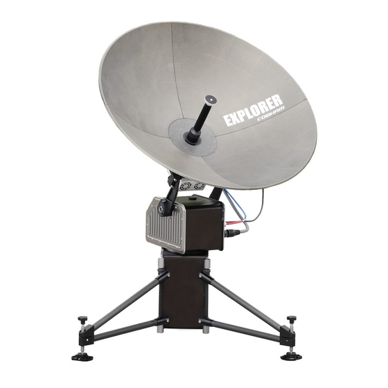
Antenna System for Inmarsat Global Xpress 2.1.1 Overview The EXPLORER 6075LX is a stabilized auto-acquire fly-away VSAT antenna system, designed for operation in Ka-band. The terminal includes a fully integrated iDirect Core Module, and is configured specifically for operation on the Inmarsat Global Xpress Ka-band network. -
Page 13: Figure 2-1: Major System Components
EXPLORER 6075LX Stabilized Auto-Acquire Antenna System for Inmarsat Global Xpress System units The system has the following system units: 1. One 2-axis motorized antenna positioner with Inter-Facility Link and cabling interface ports for BUC power. 2. Reflector and RF assembly including filter/polarizer, BUC, and LNB (Low Noise Block Down-converter). -
Page 14: Figure 2-2: Gx Coverage Map
EXPLORER 6075LX Stabilized Auto-Acquire Antenna System for Inmarsat Global Xpress 2.1.2 Satellite service The EXPLORER 6075LX operates in the Ka-band (19.2 to 30 GHz) and uses the Inmarsat Global Xpress service, see below. Global Xpress (GX) service The Global Xpress service from Inmarsat delivers consistent high-performance download speeds of up to 50 Mbps and 5 Mbps over the uplink. -
Page 15: Description Of The System Components
2.2.2 RF assembly The RF assembly for EXPLORER 6075LX includes the BUC, LNB, reflector hub, filter/polarizer, and Ka feed horn. It also contains brackets that are attached to mounting blocks on the elevation arms. Once the RF assembly is mounted, the thumb screws beneath the blocks hold the brackets securely in place. -
Page 16: Figure 2-4: Assembled 75 Cm Reflector With Center Hub And 4 Petals
Description of the system components 2.2.3 Reflector The reflector is a 75 cm reflector, consisting of a center hub and 4 interchangeable petals. The petals are made entirely of carbon-fiber composite with the exception of the metallic latches. The aluminum latches are used to secure the petals to the hub. Two smaller latches along the edge of the petals attach the reflector petals to each other. -
Page 17: Figure 2-6: Keypad And Display (Example)
2.2.5 Web interface for setup and troubleshooting The EXPLORER 6075LX has a built-in web interface, which has two levels: • Mobile web interface, used for basic operations and status. Accessed from a smartphone or tablet via WLAN. For details see Mobile web interface on page 4-1... -
Page 18: Part Numbers
Port 4 is configured as DHCP client by default. The EXPLORER 6075LX has a WLAN module. Access to one of the Local IP ports using WLAN must be set up in the web interface, see To configure the LAN network on page 4-6. - Page 19 Part numbers 2.3.2 Accessories The following accessories are available from Cobham SATCOM: Part number Description 403160P EXPLORER 6000 Series Power Supply 403160P-010 EXPLORER 6000 Series Power Supply Extension cable (10 m) 406616C-070 EXPLORER 6075LX Feed Horn 2.3.3 Spare parts For information on available spare parts, log into https://sync.cobham.com/...
-
Page 20: Assembly & Start Up
• To disassemble and pack the antenna What’s in the box 3.1.1 To unpack Two transit cases contain the EXPLORER 6075LX: • Case with RF assembly and reflector petals (left) • Case with Base Unit and antenna positioner (right) Figure 3-1: Transit cases CAUTION! Be careful when handling the feed horn and the RF assembly. - Page 21 What’s in the box The cases contain the following items: • Base Unit with antenna positioner • RF package • Ka feed horn • One set of reflector petals (4 pcs.) for 75 cm reflector • DC input cable 2.5 m w. open leads •...
-
Page 22: To Assemble The Explorer 6075Lx
3.2.2 Assembly The EXPLORER 6075LX ships from the factory calibrated and ready for use. To be fully operational, you must deploy the Base Unit, install the RF assembly and the reflector, and connect the IFL and power cables. After power-up, the system will auto-acquire the network within typically five minutes. -
Page 23: Figure 3-3: Brackets With Thumb Screws For Mounting Rf Assembly
To assemble the EXPLORER 6075LX 5. Retract the thumb screws on the mounting blocks, located on the elevation arms on the antenna positioner. Figure 3-3: Brackets with thumb screws for mounting RF assembly 6. Insert the brackets of the RF assembly down into the mounting blocks on the elevation arms. -
Page 24: Figure 3-6: Locking Mechanisms For The Petals
To assemble the EXPLORER 6075LX 9. Release the four locking mechanisms on the reflector hub on the RF assembly. Figure 3-6: Locking mechanisms for the petals 10.Insert the bottom petals and latch them along the edge of each petal to carefully secure the reflector petals into place. -
Page 25: Figure 3-10: Connectors On Antenna Positioner
To assemble the EXPLORER 6075LX 3.2.3 Cable connections Connector overview The EXPLORER 6075LX has the following connectors: (connects to BUC) (connects to LNB) BUC M&C (connects to BUC) Figure 3-10: Connectors on antenna positioner DC power Port 2-3, User data... -
Page 26: Figure 3-12: Tx, Rx And Buc Cables
To assemble the EXPLORER 6075LX Connect cables 1. Connect the RF cables: (1) BUC power cable between the circular connector on the BUC and the MIL connector marked BUC M&C on the antenna positioner. (2) Transmit (Red, Tx) cable between the N connector on the BUC and the N-connector marked Tx on the antenna positioner. - Page 27 1. Connect the circular connector from the EXPLORER 6000 Series Power Supply to the DC Power connector on the Base Unit. If you need a longer cable, an extension cable (10 m) is available from Cobham Note SATCOM (part number 403160P-010).
-
Page 28: Figure 3-14: Dc Power, Cable Connector Pinout
• Connect pin 2- (Enable) to GND (pin 2+). This means you can only switch the EXPLORER 6075LX on and off using the Power switch on the Base Unit. • Connect a remote on/off switch between pin 2- (Enable) and pin 2+ (GND). -
Page 29: Power On And Auto-Pointing
Power on and auto-pointing Power on and auto-pointing The system is set to automatically point and acquire a connection (default), when a satellite profile is activated. However, for best results select a satellite profile with the current satellite region, see To select and activate a satellite profile on page 4-2. -
Page 30: Figure 3-15: On/Off Button
Note temperature. Wait for the heating event in the display to disappear. Auto-acquisition overview The following points describe the typical auto-pointing algorithm. The EXPLORER 6075LX performs the following actions: 1. Detects mechanical home position for azimuth and elevation. 2. Calculates the azimuth/elevation look angles using the inputs from GNSS (GPS, Glonass etc.), compass, accelerometer and gyroscope. -
Page 31: Figure 3-16: To Stow The Antenna Using The Web Interface
To stow the antenna using the web interface 1. Connect a PC to the connector marked Port 1, Service (or Port 4, Management). 2. Open your Internet browser and enter the IP address of the EXPLORER 6075LX. The default IP address is http://192.168.0.1. -
Page 32: To Disassemble And Pack The Antenna
To disassemble and pack the antenna To stow the antenna manually See To stow the antenna manually on page 5-18. To disassemble and pack the antenna 1. Press the ON/OFF button on the unit to power it off. WARNING! The Base Unit may get very hot in sunny and hot weather conditions. -
Page 33: Setup And Operation
Chapter 4 Setup and operation This chapter has the following sections: • The web interface • Antenna mode • Local IP and WLAN • To deploy, stow or stop the antenna • Reporting • To jog the antenna • Navigation •... - Page 34 • Eventlist shows a list of currently active events (if any). • Desktop gives access to the full version of the web interface. • Help opens the user & installation manual for the EXPLORER 6075LX VSAT system. To select and activate a satellite profile 1.
-
Page 35: Figure 4-1: Web Interface > Dashboard
The web interface 4.1.2 Configuration web interface Use the built-in web interface of the Base Unit to make a full configuration of the VSAT system. You can use a standard Internet browser. The settings specifically related to service are described in Chapter 5, Service. Note To access the configuration web interface To access the web interface of the Base Unit do as follows:... - Page 36 IP network on page 4-8. New installation or forgotten password To get temporary administrator access to the EXPLORER 6075LX, do as follows: 1. On the ACU keypad, push and hold the left arrow key for 5 seconds. 2. Wait for the very short display of Local administration, followed by the event text: 0807F-0 WARNING Local administration enabled.
-
Page 37: Figure 4-2: Top Bar In Dashboard, Example
The web interface Information and controls in the top bar of the web interface The top bar, which is independent of the selected page, shows the signal strength, the deployed status, the system status, and, if an event is active, a warning icon. The buttons Deploy, Stow and Stop are also available from the top bar. - Page 38 The web interface Information fields on the Dashboard DASHBOARD Description GNSS position Position reported by the GNSS module or entered manually Base orientation Orientation of the mounting base relative to estimated North Satellite profile Name of the currently active satellite profile Satellite position Position of the satellite selected in Satellite profile RX polarization...
-
Page 39: Antenna Mode
3. If you want to leave the antenna in a fixed installation, select Fixed installation and click Apply. This means the EXPLORER 6075LX automatically logs on to the network after reboot in case of a temporary power loss. No user action is required. Fixed installation is allowed after the EXPLORER 6075LX has been pointed to the satellite. -
Page 40: Local Ip And Wlan
Local IP and WLAN Local IP and WLAN 4.3.1 To configure the local IP network On this page you can set up the local IP ports and enter a host name. The host name helps identifying the VSAT system. To configure the local IP ports, do as follows: 1. - Page 41 Local IP and WLAN Make sure that the networks do not use IP address ranges that overlap. Important Do not connect units with the IP address 192.168.1.3 to the Base Unit. This IP address is reserved. Sections Preferred use NETWORK The host name is used for identifying the VSAT system, and is displayed in Host name the web interface (right side of top line, next to the product name).
- Page 42 Enabled: WLAN access point is shown to other users. Disabled: WLAN access point is hidden. 7. Type in the SSID of your choice or accept the default SSID, which is Cobham. The SSID is the name of the wireless local area network. It is maximum 32 characters.
-
Page 43: To Deploy, Stow Or Stop The Antenna
To deploy, stow or stop the antenna • WPA-PSK, enter the encryption key in hexadecimal or text format. • WPA2-PSK, enter the encryption key in hexadecimal or text format. We strongly recommend adding encryption to the WLAN connection, in Important order to protect your network! 9. -
Page 44: Reporting
Reporting Reporting 4.5.1 E-mail setup To be able to send diagnostics reports and other system information using e-mail you must set up a couple of parameters. Contact your IT department for the specific data. To configure the e-mail setup, do as follows: 1. - Page 45 Reporting Remote syslog You can set up the antenna to send each syslog message to a syslog server to advise the system administrator of the current status of the antenna. To set up sending syslog messages to a syslog server, do as follows: 1.
-
Page 46: To Jog The Antenna
To jog the antenna To jog the antenna You can use the Jog function to deliberately offset the antenna position. This is useful for testing and troubleshooting and sometimes also during commissioning. 1. Connect a PC to the Port 1 connector at the Base Unit. You may also use WLAN, if it is configured. -
Page 47: Navigation
Manual Enter a value for the direction of the EXPLORER 6075LX as an alternative to the magnetic heading (0 to 360 degrees, precision ±20°). 0 degrees points North, 180 degrees points South. - Page 48 Navigation 3. Set the Position mode: Position mode Description GNSS GNSS module is used for current position (default). At GNSS, select one of the following from the drop-down list: • GPS (default) • BEIDOU • GPS + BEIDOU • GLONASS •...
-
Page 49: Administration
Administration Administration In this section of the web interface you can configure the following administrative settings: • Administrator access to the web interface (user name, password) • User permissions (for guest user) • To import and export a system configuration 4.8.1 Administrator access to the web interface (user name, password) - Page 50 To change the guest login password (User administration) The administrator must create a user password before the user can access the Note EXPLORER 6075LX the first time. When you are logged in as administrator you can create or change the guest login password as follows: 1.
- Page 51 • Changes in the network setup • User permissions • Base Unit display: brightness setting 2. Click Reset to factory default. You can also power cycle the EXPLORER 6075LX, see Power cycle on page 5-3. 98-165591-B Chapter 4: Setup and operation 4-19...
-
Page 52: Keypad And Display Menus
Keypad and display menus Keypad and display menus 4.9.1 Keypad and display With the display menu you can do basic operations such as deploy, stow and stop the antenna. You can also select which satellite profile to use and see the current status of the system. - Page 53 Keypad and display menus • <Modem TX> = [m,M], M (valid TX signal on modem) or m (no valid TX signal on modem) • <ODU TX> = [a,A] A (valid TX signal on antenna) or a (no valid TX signal on antenna) •...
-
Page 54: Figure 4-8: Menu Tree In The Display
Keypad and display menus 4.9.4 The menu tree The menu tree below shows the available menus in the Base Unit display menu system. OPERATION DEPLOY STOW STOP START MANUAL POINTING AZI ELE SIG ENALBLE/DISABLE POINTING PROFILE ANTENNA STATE MAIN <profile 1> ELEVATION OPERATION <profile 2>... - Page 55 Keypad and display menus Top-level menu Top-level menu Description MAIN View with current status of the VSAT system. The status screen is displayed again after a time out of 10 minutes. New events are shown in this display. If an event is displayed, press OK to jump directly to EVENTS for viewing the currently active events.
- Page 56 Keypad and display menus PROFILE Description Lists the available satellite profiles. Use and to go through the <PROFILE> profiles and press OK to select the profile you want to activate. ANTENNA Description POINTING ANTENNA STATE: Current state of the antenna, e.g. TRACKING ELEVATION: Current elevation angle of the antenna AZIMUTH: Current azimuth of the antenna, with reference to North GNSS...
- Page 57 Keypad and display menus NETWORK Description HOST NAME Define a name for the VSAT system PORT 1 IP Current IP address for Port 1 (service port) PORT 1 MASK Current netmask for Port 1 PORT 4 IP Current IP address for Port 4 PORT 4 MASK Current netmask for Port 4 DEFAULT GATEWAY...
-
Page 58: Snmp Support
SNMP is always enabled on all Ethernet interfaces. The SNMP community string is public. The EXPLORER 6075LX offers via SNMP most of the data that are available from the DASHBOARD web pages. Detailed documentation about supported OIDs can be found in the MIB file for your VSAT system. -
Page 59: Service
If this manual does not provide the remedies to solve your problem, contact your service provider. 5.1.1 Preventative maintenance The EXPLORER 6075LX is constructed to require a minimum amount of regular maintenance. WARNING! Potentially hot surface when the system is operated in hot environments without the possibility for ventilation. Contact may cause burn. -
Page 60: Figure 5-1: Web Interface: Helpdesk
5. Click Legal notices to display the license text for the source code of the parts of the EXPLORER 6075LX software that fall under free and open source software. 6. In the section Download Reports click the button Download. The diagnostics report (txt file) is downloaded to your computer. -
Page 61: Figure 5-2: To Reset The System
General support • Satellites - Satellite profiles • Operation - Current modem and navigation parameters. • POST - results of the Power-On-Self-Test • Active Events - lists the currently active events • Events - List of all cleared events. • System log 7. -
Page 62: Figure 5-3: Web Interface: Settings - List Of Satellite Profiles (Example)
General support 5.1.4 Satellite profiles and modem profiles 5 satellite profiles with the GX Modem are already set up at the factory (1 for each satellite and one Auto). You may add a satellite profile with the generic modem for troubleshooting purposes. -
Page 63: Figure 5-4: Web Interface: Settings, Vsat Modem Profile - Supported Modems
During the P1dB compression the antenna will point away from the satellite and transmit on 29 GHz to 30 GHz. The EXPLORER 6075LX will show BUC Calibration on the DASHBOARD and the Base Unit display. This may take up to 10 minutes. -
Page 64: Figure 5-6: Web Interface: Service > Modem (Example)
General support Use the Internet browser Firefox to access the iDirect Modem web interface. Important 1. Connect a PC to Port 1 on the Base Unit. 2. Open Firefox and enter the web interface. 3. Select SERVICE > Modem. Figure 5-6: Web interface: SERVICE > Modem (example) 4. -
Page 65: Figure 5-8: Web Interface: Service > Modem Access Configuration
General support Modem access configuration For the built-in GX modem, the section Modem access configuration is pre filled. If you want to use a different access type instead of the default HTTPS tunnel to access the web interface of the built-in modem, you can change it here. Figure 5-8: Web interface: SERVICE >... -
Page 66: Figure 5-9: Web Interface: Service > Antenna Data
5.1.7 Self test You can start a self test of the antenna alone or of the complete VSAT system. The EXPLORER 6075LX will reboot to perform the self test. Rebooting the Important Base Unit will terminate all existing connections. 1. Select SERVICE > Self test. - Page 67 General support 5.1.8 Proxy server settings in your browser If you are connecting your computer using a LAN or WLAN interface, the Proxy server settings in your browser must be disabled before accessing the web interface. Most browsers support disabling of the Proxy server settings for one specific IP address, so you can disable Proxy server settings for the web interface only, if you wish.
-
Page 68: Software Update
1. Power up the EXPLORER 6075LX. 2. Connect a PC to Port 1 (Service port, standard). 3. Open your Internet browser and enter the IP address of the EXPLORER 6075LX. The default IP address is http://192.168.0.1. 4. Type in the user name admin and the admin password press and hold the left arrow key for 5 seconds and enter the user name admin. -
Page 69: Figure 5-11: Verifying Software Update
To verify the software update 1. The software version can be viewed in the DASHBOARD window of the web interface. 2. After completing the software update procedure, the EXPLORER 6075LX will perform a POST (Power On Self Test). 3. When the POST has finished, the green Pass/Fail LED on the keypad must become steadily green. - Page 70 Touch Commissioning (OTC) on page 5-5 for information how to connect to the web interface of the GX modem. Software recovery (safe mode) If the EXPLORER 6075LX has become inoperative, a software recovery update may bring it back into an operational state. To make a software recovery, do as follows: 1.
-
Page 71: Status Signaling With Leds And Status Messages
Status signaling with LEDs and status messages Built-In Test Equipment The EXPLORER 6075LX has a Built-In Test Equipment (BITE) function in order to make fault diagnostics easy during service and installation. The BITE test is performed during: • Power On Self Test (POST), which is automatically performed each time the system is powered on. -
Page 72: Figure 5-12: Modem Information
5.3.2 Status information of the modem The modem status is shown in the display of the EXPLORER 6075LX in the menu Modem (see The menu tree on page 4-19). The current status is communicated by a text string: Steady green, red or yellow, or flashing green, red or yellow: NET LED, STAT LED, TX LED, RX1 LED, RX2 LED, PWR LED, TEMP LED, FAN LED. -
Page 73: Manual Pointing
Manual pointing Manual pointing 5.4.1 To point the antenna manually If auto-acquisition is not possible you can manually bring the antenna into the correct position. Before manually pointing the antenna make sure it is placed on level ground Important and with secured support legs as described in Assembly on page 3-3. Do as follows: 1. -
Page 74: Figure 5-16: Manual Pointing, Elevation Adjustment
The value for current elevation (third number from the left) is only valid if the Note EXPLORER 6075LX is level. 12.Observe the display for appearing signal strength bars. When the signal is detected, slowly scan the azimuth angle back and forth to maximize the signal strength (the number SIG in the display). - Page 75 Manual pointing 17.Remount the cover for the elevation adjustment port Leave the adjustment tool inserted in the azimuth adjustment port until you Important have finished using the antenna with manual pointing. It keeps the antenna positioner in place (holds the current azimuth) and protects the azimuth adjustment port against rain and dust.
-
Page 76: To Return Units For Repair
Your dealer, installer or Cobham SATCOM partner will assist you whether the need is user training, technical support, arranging on-site repair or sending the product for repair. Your dealer, installer or Cobham SATCOM partner will also take care of any warranty issue. -
Page 77: Appendix A Technical Specifications
Appendix A Technical specifications This appendix has the following sections: • General specifications • Outline drawings 98-165591-B... -
Page 78: General Specifications
General specifications General specifications EXPLORER 6075LX 0.75m Stabilized Auto-Acquire Fly-Away Antenna System for Inmarsat Global Xpress® Antenna Characteristics Mechanical Feed 2 Port Circular Axis Drive System 2-Axis Positioner 19.2 - 20.2 Mount Geometry Elevation over Azimuth Frequency (GHz) Travel 29 - 30 - Azimuth ±... -
Page 79: Outline Drawings
Outline drawings Outline drawings Figure A-1: Rear view, EXPLORER 6075LX 98-165591-B Appendix A: Technical specifications... -
Page 80: Figure A-2: Side View, Explorer 6075Lx
Outline drawings Figure A-2: Side view, EXPLORER 6075LX 98-165591-B Appendix A: Technical specifications... -
Page 81: Figure A-3: Top View, Explorer 6075Lx
Outline drawings Figure A-3: Top view, EXPLORER 6075LX 98-165591-B Appendix A: Technical specifications... -
Page 82: Appendix B System Messages
• CM (Continuous Monitoring) – automatically performed while the system is in operation. When the EXPLORER 6075LX detects an event that requires your action, it issues an event message and the red Fail/Pass LED in the LED panel of the Base Unit is lit. As long as an event is active, it is shown in the Base Unit display and in the web interface (in HELPDESK >... -
Page 83: List Of Events
List of events List of events B.2.1 Events from Base Unit Event ID Severity Description Explanation 08060-0 WARNING Antenna modem ACU/Antenna communication error detected (framing and parity). If the situation is persistent, check if cable specifications comply (length and attenuation). 08063-0 ERROR Antenna... - Page 84 List of events Event ID Severity Description Explanation 08073-0 WARNING Slave connection The system is configured as a dual antenna master, but no dual antenna slave is connected to it. Either disable the dual antenna master in the web interface or configure a another system as a dual antenna slave.
- Page 85 List of events Event ID Severity Description Explanation 0807E-0 WARNING Keyline signal The keyline signal on the dual antenna master does not match the keyline signal on the slave. Check that the keyline splitter cable is connected to the RS422 connectors.
- Page 86 List of events Event ID Severity Description Explanation 08109-0 ERROR Antenna XIM There is a mismatch in the antenna configuration data. data Either the PCM or the VIM in the antenna are malfunctioning or one of them has been replaced. In the latter case, select which is the original device in the web interface and restart the system.
- Page 87 List of events Event ID Severity Description Explanation 08880-0 ERROR WLAN Configuration of WLAN module failed. configuration error 08A00-0 WARNING GX Core Module There is a problem with the Core Module fan. Check/clean and replace if necessary. 08A01-0 WARNING GX Core Module There is a problem with the Core Module heater.
- Page 88 List of events Event ID Severity Description Explanation 0B010-0 ERROR PSM link/SW Link to the PSM module could not be established. Either the version PSM board is malfunctioning, or - if the system software has just been updated - the software is too old and is not compatible with the PSM hardware.
- Page 89 List of events B.2.2 Events from antenna Event ID Severity Description Explanation 0A001-0 ERROR Production data Production data is invalid. 0A002-0 ERROR XIM internal Antenna configuration data stored in the PCM module is invalid. 0A003-0 ERROR XIM external Antenna configuration data stored in the VIM module is invalid.
- Page 90 List of events Event ID Severity Description Explanation 0A021-0 ERROR Azi axis Azimuth axis zero reference not found. Check belt and zero calibration reference module. Info: 0x00000001: Timeout (operation did not complete in time) 0x00000010: Encoder or mechanical problem 0x00000020: Zero reference not found 0x00000040: End stop not found.
- Page 91 List of events Event ID Severity Description Explanation 0A03B-0 ERROR Azi DDM The azimuth motor control has detected one of the following shutdown situations: Extreme temperature, voltage, current or velocity. The motor was then shut down. This is usually a temporary situation and is probably fixed by a restart of the system.
- Page 92 List of events Event ID Severity Description Explanation 0A050-0 ERROR Azi DDM Communication error between PCM and azimuth communication DDM/DMD/FDM. Check SUB-D connectors and cables. 0A051-0 ERROR Xel DDM Communication error between PCM and cross-elevation communication DDM/DMD/FDM. Check SUB-D connectors and cables. 0A052-0 ERROR Ele DDM Communication error between PCM and elevation...
- Page 93 List of events Event ID Severity Description Explanation 0A05D-0 WARNING ISM warning The ISM has temporarily observed an unusual situation for temperature or voltage. No user interaction required. If repeated after cooldown and reboot, check if the ISM or cables around it are defective. 0A05E-0 WARNING Low elevation The antenna is not allowed to transmit because the elevation is too low.
-
Page 94: Appendix C Approvals
EXPLORER 6075LX system. Note that the simplified EU Declaration of Conformity covers a series of EXPLORER 6000 products. The full Declarations of Conformity can be found on the Cobham SATCOM web site as described in the simplified EU Declaration of Conformity. - Page 95 This device complies with Industry Canada license-exempt RSS standard(s). Operation is subject to the following two conditions: (1) this device may not cause interference, and (2) this device must accept any interference, including interference that may cause undesired operation of the device. Le présent appareil est conforme aux CNR d'Industrie Canada applicables aux appareils radio exempts de licence.
-
Page 96: Glossary
Glossary Glossary Antenna Control Unit. Another name for the Base Unit in the VSAT system. Above Deck Unit. Another name for antenna. BeiDou Chinese satellite navigation system. BITE Built-In Test Equipment Continuous Monitoring DHCP Dynamic Host Configuration Protocol. A protocol for assigning dynamic IP addresses to devices on a network. - Page 97 Glossary Inter-Facility Link IMSO International Mobile Satellite Organisation. An intergovernmental organisation that oversees certain public satellite safety and security communication services provided via the Inmarsat satellites. Ingress Protection. An international classification system for the sealing effectiveness of enclosures of electrical equipment against the intrusion into the equipment of foreign bodies (i.e.
- Page 98 Glossary Receive SMTP Simple Mail Transfer Protocol SNMP Simple Network Management Protocol. An Internet-standard protocol for managing devices on IP networks. It is used mostly in network management systems to monitor network-attached devices for conditions that warrant administrative attention. Secure SHell. A network protocol for secure data communication, remote shell services or command execution and other secure network services between two networked computers that it connects via a secure channel over an insecure network.
-
Page 99: Index
Index Index access deploy , 4-18 , 5-15 limit manually , 4-9 activate satellite profile DHCP client , 4-24 , 4-9 with display and keypad DHCP server , 4-2 , 5-2 with smartphone or tablet diagnostic report activation display , 2-3 , 4-20 service ACU, description... - Page 100 Index position , 4-15 fixed keypad position mode , 5-15, 5-16 description , 4-16 GNSS , 4-16 manual , 5-13 POST LAN cable , 5-13 Power On Self Test , 3-7 shielded , 2-7 power supply LAN configuration , 4-18 protect access to settings , 4-9 DHCP client...
- Page 101 Index system , 5-3 ACU reset, keys to press system configuration , 4-19 copy , B-1 System messages tablet , 4-2 mobile web interface , A-1 technical data troubleshooting , 5-2 diagnostic report , 5-10 updating software , 4-19 upload configuration user permissions , 4-18 setup...
- Page 102 98-165591-B www.cobham.com/satcom Cobham Public...
Need help?
Do you have a question about the EXPLORER 6075LX and is the answer not in the manual?
Questions and answers