
Related Manuals for COBHAM EXPLORER 7100GX


Summary of Contents for COBHAM EXPLORER 7100GX
- Page 1 EXPLORER 7100GX 1.0 m Drive-Away VSAT System for Inmarsat GX® Installation and user manual...
- Page 3 EXPLORER 7100GX 1.0 m Drive-Away VSAT System for Inmarsat GX Installation and user manual Document number: 98-147366-A Release date: 2 September 2015...
- Page 4 In the event of any discrepancies, the English version shall be the governing text. Thrane & Thrane A/S is trading as Cobham SATCOM. Copyright © 2015 Thrane & Thrane A/S. All rights reserved.
-
Page 5: Safety Summary
Cobham SATCOM may perform service - failure to comply with this rule will void the warranty. Power supply The voltage range for the EXPLORER 7100GX is 100 – 240 VAC (nominal), 4 A, 50/60 Hz. WARNING! Before disassembling or performing any maintenance or upgrades, unplug the unit from power source. - Page 6 FCC §15.105: Information to the User NOTE: This equipment has been tested and found to comply with the limits for a Class B digital device, pursuant to part 15 of the FCC Rules. These limits are designed to provide reasonable protection against harmful interference in a residential installation.
-
Page 7: Table Of Contents
Chapter 3 Installation & start up What’s in the box ......................3-1 3.1.1 To unpack ..........................3-1 3.1.2 Initial inspection ........................3-2 To install the EXPLORER 7100GX .................3-2 3.2.1 Prerequisites ..........................3-2 3.2.2 Vehicle installation ......................3-3 3.2.3 Installation of the ACU and GMU ................3-3 3.2.4... - Page 8 5.2.2 Software update procedure ...................5-9 Status signalling with LEDs and status messages ........ 5-12 5.3.1 LEDs on the keypad of the EXPLORER 7100GX ..........5-12 5.3.2 Status information of the modem ................5-13 To return units for repair ..................5-14...
-
Page 9: About This Manual
1.1.1 Intended readers This is an installation and service manual for the EXPLORER 7100GX system, intended for users of the system and service personnel. It is important that you observe all safety requirements listed in the beginning of this manual, and install the system according to the guidelines in this manual. -
Page 10: Precautions
Some materials can be dangerous. CAUTION! Do not use materials that are not equivalent to materials specified by Cobham SATCOM. Materials that are not equivalent can cause damage to the equipment. Chapter 1: About this manual 98-147366-A... -
Page 11: Chapter 2 Introduction
2.1.1 Overview The EXPLORER 7100GX is a 1.0 m drive-away antenna system, designed for operation in the Ka-band. The GX modem, also known as the iDirect Core Module, commands the system to automatically acquire an operational satellite within five minutes based on the terminal's GPS location. -
Page 12: Global Express Service
2.1.2 Global Express service The EXPLORER 7100GX is a unique GX antenna system operating in the K/Ka-band (19.2 to 30 GHz). It is used with the Global Xpress service from Inmarsat, delivering consistent high- performance download speeds of up to 50 Mbps and 5 Mbps over the uplink. The following figure shows the coverage map of the GX service at global service introduction. -
Page 13: Description Of The System Components
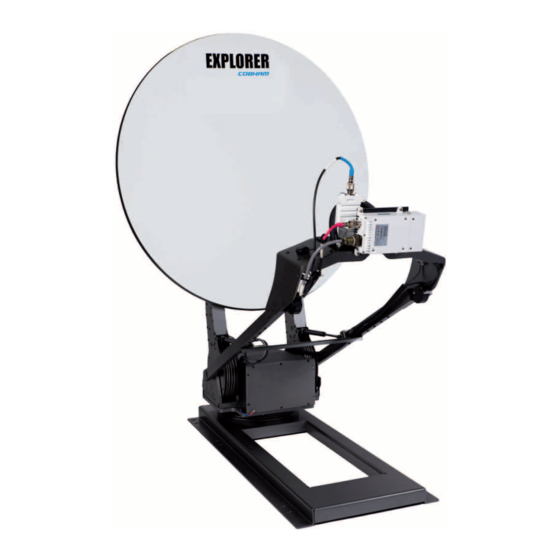
Antenna positioner Figure 2-3: EXPLORER 7100GX antenna with antenna positioner Cable drive system The cable drive system uses highly reliable aircraft control cables in a redundant configuration to achieve a lightweight, very stiff drive system with zero backlash. This high- tech performance is achieved using low-tech components, by simply wrapping the cable around the drive capstan several times before wrapping the larger drive drum. - Page 14 Description of the system components RF assembly Figure 2-4: Cable drive system Secondary drive system The cable drive system for azimuth is driven by a low backlash worm gear, set with a 15:1 ratio. The cable drive system for elevation is set at 40:1. The low backlash of the worm gear drive is reduced further by the cable drive ratio.
-
Page 15: Reflector And Rf Assembly
2.2.2 Reflector and RF assembly The EXPLORER 7100GX has a prime focus, offset parabolic, single piece 1.0 m composite resin/fibre reflector. The RF assembly includes the BUC, LNB, filter/polarizer, and feed horn. It also contains brackets that are attached to mounting blocks on the elevation arms. The BUC and LNB are mounted closely to the filter/polarizer to reduce the need for wave guides. -
Page 16: Keypad And Display
The display has a two line menu system. The display also supports two status lines (Upper and Lower) for compact satellite and antenna information. For a description of the LED light indicators see LEDs on the keypad of the EXPLORER 7100GX on page 5-12. 2.2.5 Web interface for setup and troubleshooting To fully configure the EXPLORER 7100GX, use the built-in web interface. -
Page 17: Lan Ports And Wlan
• LAN 5 is used to control the GMU. The EXPLORER 7100GX has a WLAN module. Access to one of the LAN ports using WLAN must be set up in the web interface, see To configure the LAN network on page 4-5. -
Page 18: Part Numbers
Part numbers Part numbers The EXPLORER 7100GX has the following part numbers: Part number Description 407140B-50001 EXPLORER Antenna Control Unit 407023-B-00500 EXPLORER GX Modem Unit 300224 Antenna Table 2-1: Part numbers for the EXPLORER 7100GX Chapter 2: Introduction 98-147366-A... -
Page 19: Installation & Start Up
Chapter 3 Installation & start up This chapter has the following sections: • What’s in the box • To install the EXPLORER 7100GX • Start up and daily use • To stow the antenna What’s in the box 3.1.1 To unpack Unpack the antenna, ACU and GMU and check that the following items are present: •... -
Page 20: Initial Inspection
To install the EXPLORER 7100GX 3.1.2 Initial inspection Inspect the cases immediately upon receipt for evidence of damage during transport. If the shipping material is severely damaged or water stained, request that the carrier's agent be present when opening the cases. Save all packing material for future use. -
Page 21: Vehicle Installation
To install the EXPLORER 7100GX 3.2.2 Vehicle installation To install the antenna to the transport vehicle or trailer do as follows: 1. Ensure the rear of the antenna positioner faces towards the front of the vehicle. This side towards the... - Page 22 To install the EXPLORER 7100GX Figure 3-2: Connection between antenna, ACU and GMU Connect the cables as described below: 1. Connect LAN port 1 Control on the GMU to the LAN 5 control port on the ACU. 2. Connect the GMU's Tx Out port to the ACU's Tx In port.
-
Page 23: Start Up And Daily Use
Start up and daily use wired directly from an internal stow switch with both normally-connect (NC) and normally- open (NC) connections, see the following figure. Figure 3-3: Stow connector (female) Start up and daily use After power on you must deploy the antenna. During commissioning you might need to manually jog the antenna. -
Page 24: To Jog The Antenna
2. After power up wait until the ACU display shows READY TO MOVE 3. Connect a PC to the LAN1 connector at the ACU. 4. Open your Internet browser and enter the IP address of the EXPLORER 7100GX. The default IP address is http://192.168.0.1. -
Page 25: To Stow The Antenna
Start up and daily use 2. Open your Internet browser and enter the IP address of the EXPLORER 7100GX. The default IP address is http://192.168.0.1. 3. Type in the user name admin and the password 1234 (default) to access the Dashboard as an administrator. - Page 26 Start up and daily use 3. Type in the user name admin and the password 1234 to access the Dashboard as an administrator. 4. Go to the page SERVICE > ANTENNA and click the button Stow. Figure 3-7: To stow the antenna using the web interface 5.
-
Page 27: To Drive With The Antenna Installed
Start up and daily use 4. Manually decrease the elevation angle, until the antenna is completely folded to the stow position. Figure 3-10: Elevation manual drive 3.3.4 To drive with the antenna installed The antenna must be stowed when you drive the vehicle. The maximum speed depends on your installation, but it must never exceed 100 mph or 161 km/h. - Page 28 Start up and daily use 3-10 Chapter 3: Installation & start up 98-147366-A...
-
Page 29: Setup And Operation
Connection to the web interface To connect to the web interface of the ACU do as follows: 1. Switch on the EXPLORER 7100GX system. Wait until the LEDs on the front plate of the ACU show that the system is ready to be configured. - Page 30 Setup using the web interface When the login screen is displayed you have verified that the connection to the EXPLORER 7100GX can be established. The web interface is ready for use. You can continue to configure the system. Figure 4-1: Logon screen If you cannot establish a connection there might be problems with the Proxy server settings of your PC.
- Page 31 The DASHBOARD is the first screen that is displayed when the user or administrator enters the IP address of the web interface of the ACU. It shows the properties and status of the EXPLORER 7100GX. The web interface has the following sections: Figure 4-4: Web interface: DASHBOARD...
- Page 32 For information see User permissions (guest login) on page 4- Information fields on the Dashboard DASHBOARD Description System status Current status of the EXPLORER 7100GX Examples: Antenna software upload Antenna POST (Power-On Self Test) Ready (waiting for data from the modem or no satellite profile...
-
Page 33: To Configure The Lan Network
Important the Internet. It must be located behind a dedicated network security device such as a firewall. If any ports of the EXPLORER 7100GX are exposed to the Internet you must change the default passwords as anyone with access and malicious intent can render the EXPLORER 7100GX inoperable. - Page 34 Important Sections Preferred use NETWORK The host name is used for identifying the EXPLORER 7100GX. The default Host host name is acu. You can change the name. Letters (a-z), digits (0-9) and name hyphen (-) are allowed as legal characters.
- Page 35 Setup using the web interface Sections Preferred use LAN Port 2, 3 User data ports, configured automatically by the modem. The Virtual LAN and 4 (VLAN) table shows this configuration. LAN Port 5 No connector, only internal connection.This network is connected to the modem (iDirect GX Modem).
-
Page 36: Wlan Settings
Disabled: WLAN access point is hidden. 6. Type in the SSID of your choice or accept the default SSID, which is Cobham. The SSID is the name of the wireless local area network. It is a text with maximum 32 characters. -
Page 37: Navigation
You can logon as an administrator or as guest (user name: guest, password: guest). The Administration settings require an Administration user name and password. To log on as administrator, do as follows: 1. Open your Internet browser and enter the IP address of the EXPLORER 7100GX: http://192.168.0.1. 98-147366-A... - Page 38 Setup using the web interface 2. Enter the Administration user name admin and password 1234 (default). Figure 4-7: Web interface: Logon 3. Click Logon. 4. Select ADMINISTRATION. The Administration page is now updated to let you change the user name and password or log off Administration.
-
Page 39: User Permissions (Guest Login)
4.1.7 User permissions (guest login) You can manage user access to certain functions of the EXPLORER 7100GX system. You can allow or deny users that are not administrators (user name: guest, password: guest) access to certain functions and make these pages read-only. This is useful if you want to protect the system against unintended changes or tampering of the system. -
Page 40: Reset To Factory Default
1. Reset to factory default, see the following section for details. 2. Import a configuration from file, see section above. 4.1.9 Reset to factory default When resetting EXPLORER 7100GX to factory default, the following settings are deleted or reset to factory default: • Navigation settings • All added satellite profiles •... - Page 41 Setup using the web interface To reset the ACU to factory default settings, do as follows: 1. Select ADMINISTRATION > Factory default. Figure 4-11: Web interface: ADMINISTRATION > Factory default 2. Click Reset to factory default. Reset to factory default - GX modem CAUTION! Administrators only.
-
Page 42: Keypad And Display Menus
Signal strength Figure 4-13: Display and keypad of the ACU (example) 1. Current status of the EXPLORER 7100GX (examples): ANTENNA SOFTWARE UPLOAD ANTENNA POST (Power-On Self Test) READY (waiting for data from the modem or no satellite profile selected) -
Page 43: Navigating The Menus
Keypad and display menus After 1 hour the display is dimmed to lowest intensity. Press any key to light up the display. 4.2.2 Navigating the menus Use the keypad to navigate the menus. • Use the arrow keys and to go through the menu items or enter a number, digit by digit. - Page 44 Description MANUAL POINTING MAIN View with current status of the EXPLORER 7100GX. Example when logged on to the satellite: This view is displayed after a time out of 10 minutes. Press any key (except left arrow) to enter the menu at MAIN.
- Page 45 Keypad and display menus ANTENNA Description VERSIONS Current software version. SERIAL NUMBERS Serial number of the EXPLORER 7100GX and an Inmarsat serial number. Table 4-7: ANTENNA menu (Continued) MODEM Description MODEM TYPE Current modem type. TX ENABLE On or off, information delivered by the connected GX modem.
-
Page 46: Brightness Of The Display
Keypad and display menus EVENT Description In this menu all active events are listed. Use and to go through the <EVENT> active events. Events can be of the type WARNING or ERROR. If a new event occurs or there is a change in the event list while you are in the EVENTS menu, a * is shown in the upper left corner of the display, next to the menu name. -
Page 47: Chapter 5 Service
If this manual does not provide the remedies to solve your problem, contact your service provider. 5.1.1 Preventative maintenance The EXPLORER 7100GX is constructed to require a minimum amount of regular maintenance. Make the following checks on a regular basis: • Inspect the reflector front surface for physical damage including chips and cracks. Any substantial damage can affect antenna performance and may require the reflector to be replaced. -
Page 48: Help Desk And Diagnostics Report
3. Click Legal notice to display the licence text for the source code of the parts of the EXPLORER 7100GX software that fall under free and open source software. 4. In the section Download Reports click the button Download. The report (txt file) is downloaded to your computer. -
Page 49: Reset
To reset the GX modem to factory defaults use the web interface. See Reset to factory default - GX modem on page 4-13. Reset to factory defaults using the web interface To reset the EXPLORER 7100GX to factory defaults via the web interface see Reset to factory default on page 4-12. 98-147366-A... -
Page 50: Satellite Profiles And Vsat Modem Profiles
General support 5.1.4 Satellite profiles and VSAT modem profiles A satellite profile with the GX Modem is already set up at the factory. You may add a satellite profile with the generic modem for troubleshooting purposes. Satellite profiles – New entry and Edit Figure 5-3: Web interface: SETTINGS - list of satellite profiles (example) Each satellite profile has one assigned VSAT modem profile. - Page 51 General support VSAT modem profile – New entry and Edit To add or edit a VSAT modem profile, do as follows: 1. Go to SETTINGS > VSAT modem profiles and click New entry or Edit. The supported VSAT modem profiles are listed in the drop-down list VSAT modem. Figure 5-5: Web interface: SETTINGS, VSAT modem profile –...
-
Page 52: Gx Modem: One Touch Commissioning
General support 5.1.5 GX Modem: One Touch Commissioning You may have to make the One Touch Commissioning (OTC) for the modem. WARNING! For your safety: Active RF transmission may occur during an OTC procedure. Software updates may also occur, yet the system is in receive- only mode during such auto-updates. -
Page 53: Lnb Data Update
General support 8. The Unified Web Interface of the Core Module will indicate the modem in the network as well as the modem status in the display in the menu MODEM. 9. When commissioning is completed, test all subscribed services. 5.1.6 LNB data update If the RF assembly or the LNB has been replaced you must update the LNB data. -
Page 54: Proxy Server Settings In Your Browser
General support 5.1.7 Proxy server settings in your browser If you are connecting your computer using a LAN or WLAN interface, the Proxy server settings in your browser must be disabled before accessing the web interface. Most browsers support disabling of the Proxy server settings for one specific IP address, so you can disable Proxy server settings for the web interface only, if you wish. -
Page 55: Software Update
See To configure the LAN network on page 4- 5 for more information. 3. Open your Internet browser and enter the IP address of the EXPLORER 7100GX. The default IP address is http://192.168.0.1. 4. Type in the user name admin and the password 1234 (default) to access the Dashboard. -
Page 56: To Verify The Software Update
To verify the software update 1. The software version can be viewed in the DASHBOARD window of the web interface. 2. After completing the software update procedure, the EXPLORER 7100GX will perform a POST (Power On Self Test). 3. When the POST has finished, the green Pass/Fail LED on the keypad must become steadily green. - Page 57 GX modem (Core Module). Software recovery (safe mode) If the EXPLORER 7100GX has become inoperative, a software recovery update may bring it back into an operational state. To make a software recovery, do as follows: 1.
-
Page 58: Status Signalling With Leds And Status Messages
Status signalling with LEDs and status messages Built-In Test Equipment The EXPLORER 7100GX has a Built-In Test Equipment (BITE) function in order to make fault diagnostics easy during service and installation. The BITE test is performed during: • Power On Self Test (POST), which is automatically performed each time the system is powered on. -
Page 59: Status Information Of The Modem
5.3.2 Status information of the modem The modem status is shown in the display of the EXPLORER 7100GX in the menu Modem and also in short form in the upper status line. The current status is communicated by a text string: Steady green, red or yellow, or flashing green, red or yellow. -
Page 60: To Return Units For Repair
Cobham SATCOM Self Service Center web-portal, which may help you solve the problem. Your dealer, installer or Cobham SATCOM partner will assist you whether the need is user training, technical support, arranging on-site repair or sending the product for repair. Your dealer, installer or Cobham SATCOM partner will also take care of any warranty issue. -
Page 61: Appendix A Technical Specifications
Appendix A Technical specifications This appendix has the following sections: • Specifications • Product Dimensions Specifications Ka-Band Receive Transmit Feed 2 Port Circular Frequency range (GHz) 19.2 - 20.2 29 - 30 Gain (dBi ± 0.2) 41.0 44.5 1.5 ... - Page 62 Specifications Weights and measures Antenna, approx. weight 45 kg (100 lbs) without BUC / LNB Antenna, approx. length 156 cm (61.5") Antenna, stowed height 34.3 cm (13.5") Antenna, deployed height 151.4 cm (60") (*with load frame) GX modem unit, approx. weight 4.5 kg (10 lbs) GX modem unit, approx.
-
Page 63: Product Dimensions
Product Dimensions Product Dimensions The dimensions shown here are in centimetres, with inches shown in brackets. A.2.1 Side view (stowed) Figure A-1: Side view (stowed) A.2.2 Top view (stowed) Figure A-2: Top view (stowed) 98-147366-A Appendix A: Technical specifications... -
Page 64: Side View (Deployed
Product Dimensions A.2.3 Side view (deployed) Figure A-3: Side view (deployed) Appendix A: Technical specifications 98-147366-A... -
Page 65: Measures For Antenna Installation
Product Dimensions A.2.4 Measures for antenna installation Figure A-4: Measures for antenna installation 98-147366-A Appendix A: Technical specifications... - Page 66 Product Dimensions Appendix A: Technical specifications 98-147366-A...
-
Page 67: Appendix B System Messages
• CM (Continuous Monitoring) – automatically performed while the system is in operation. When the EXPLORER 7100GX detects an event that requires your action, it issues an event message and the red Fail/Pass LED in the LED panel of the ACU is lit. As long as an event is active, it is shown in the ACU display and in the web interface (in HELPDESK >... -
Page 68: List Of Events
List of events List of events Error code Severity Description Explanation (ID) 08065-0 ADM WARNING GNSS data Missing GPS data (fix). 08067-0 ADM ERROR PCB temperature ADM temperature too high. The ACU is not equipped with a fan, so make sure there is compliance with the environmental specifications. - Page 69 List of events Error code Severity Description Explanation (ID) 0810D-0 ADM ERROR Antenna communication Link to the ACU could not be established. Either the ACU is malfunctioning, or - if the system software has just been updated - the software is too old and is not compatible with the ACU hardware.
- Page 70 List of events Error code Severity Description Explanation (ID) 09000-0 KDM ERROR KDM 3V3 supply Internal 3V3 voltage supply error in the KDM. 09001-0 KDM ERROR KDM 12V supply Internal 12V voltage supply error in the KDM. 09002-0 KDM ERROR KDM display Display hardware error in the KDM.
-
Page 71: Appendix C Approvals
Appendix C Approvals This appendix lists the approvals for EXPLORER 7100GX. 98-147366-A... - Page 72 Appendix C: Approvals 98-147366-A...
-
Page 73: Glossary
Glossary Glossary ADU Bus Slave ACU Digital Module. A main processor board in the ACU. Antenna Module Bus Block Up Converter. The BUC can be thought of the “transmitter”, and its actions are effectively the direct opposite to the LNB. The BUC consists of the Up Converter and HPA. Continuous Monitoring Digital Video Broadcasting, a set of standards relating to digital television. - Page 74 Glossary Keyboard and Display Module of the ACU Local Area Network Light Emitting Diode Low Noise Blockdown Converter. A device used to amplify or boost the weak received signal without amplifying the noise signals (hence the “low noise” part of LNB) and to convert the high frequencies of the signal into lower frequencies, a process called down converting, for conveyance to the indoor equipment (demodulator) for processing.
-
Page 75: Index
Index Index configuration , 4-11 copy access , 4-11 export , 4-11 limit , 4-11 import acquisition , 4-5 LAN network , 4-16 manual , 4-3 site map , 4-2 search pattern , 4-1 step-by-step activation , 4-1 Configuration program , 2-2 service connect... - Page 76 Index log off , 4-11 administrator GMU web interface login GX modem , 4-11 guest , 5-6 web interface , 4-2 web interface guest logon , 4-2 password , 4-9 administrator, web interface , 4-11 permissions , 4-2 user name , 4-2, 4-11 guest login GX modem...
- Page 77 Index , 5-3 reset , 4-12 factory default , A-1 technical data , 4-10 password troubleshooting , 4-10 reset administrator password , 5-2 diagnostic report , 5-3 reset keys on ACU , 2-5 RF assembly , 5-9 updating software upload , 5-11 safe mode , 4-11...
- Page 78 98-147366-A www.cobham.com/satcom...
Need help?
Do you have a question about the EXPLORER 7100GX and is the answer not in the manual?
Questions and answers