Table of Contents
Advertisement
Quick Links
Advertisement
Table of Contents

Related Manuals for COBHAM EXPLORER 3075GX


Summary of Contents for COBHAM EXPLORER 3075GX
- Page 1 EXPLORER 3075GX Manual-Deploy Antenna System Installation and user manual...
- Page 3 EXPLORER 3075GX Installation and user manual Document number: 98-144390-A Release date: 6 March 2015...
- Page 4 In the event of any discrepancies, the English version shall be the governing text. Thrane & Thrane A/S is trading as Cobham SATCOM. Copyright © 2015 Thrane & Thrane A/S. All rights reserved.
-
Page 5: Safety Summary
Cobham SATCOM may perform service - failure to comply with this rule will void the warranty. Power supply The voltage range for the EXPLORER 3075GX is 100 – 240 VAC (nominal), 4 A, 50/60 Hz. WARNING! Before disassembling or performing any maintenance or upgrades, unplug the unit from power source. - Page 6 FCC §15.105: Information to the User NOTE: This equipment has been tested and found to comply with the limits for a Class B digital device, pursuant to part 15 of the FCC Rules. These limits are designed to provide reasonable protection against harmful interference in a residential installation.
-
Page 7: Table Of Contents
Assembly & start up What’s in the box ......................3-1 3.1.1 To unpack ..........................3-1 3.1.2 Initial inspection ........................3-2 To assemble the EXPLORER 3075GX ..............3-2 3.2.1 Prerequisites ..........................3-2 3.2.2 Assembly ..........................3-3 Start up with manual acquisition ................3-6 To stow the antenna .....................3-8 To disassemble and pack the antenna ............3-8... - Page 8 5.2.2 Software update procedure ...................5-9 Status signalling with LEDs and status messages ........ 5-12 5.3.1 LEDs on the keypad of the EXPLORER 3075GX ..........5-12 5.3.2 Status information of the modem ................5-13 To return units for repair ..................5-14...
-
Page 9: About This Manual
1.1.1 Intended readers This is an installation and service manual for the EXPLORER 3075GX system, intended for users of the system and service personnel. It is important that you observe all safety requirements listed in the beginning of this manual, and install the system according to the guidelines in this manual. -
Page 10: Precautions
Some materials can be dangerous. CAUTION! Do not use materials that are not equivalent to materials specified by Cobham SATCOM. Materials that are not equivalent can cause damage to the equipment. Chapter 1: About this manual 98-144390-A... -
Page 11: Chapter 2 Introduction
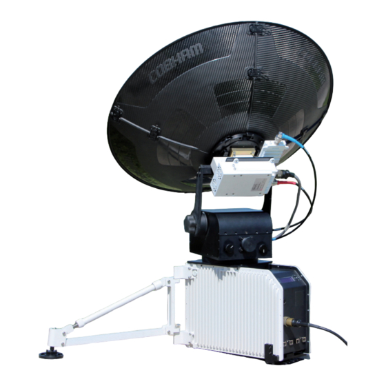
2.1.1 Overview The EXPLORER 3075GX is a manual-deploy 75 cm fly-away antenna system, designed for operation in the Ka-band. The integrated GX modem, also known as the iDirect Core Module, facilitates the acquisition of an operational satellite within five minutes based on the terminal's GPS location. -
Page 12: Global Express Service
The following figure shows the coverage map of the GX service at global service introduction. Figure 2-2: GX coverage map 2.1.3 Service activation The EXPLORER 3075GX should be activated from the start. If there are problems with the GX service contact your service provider for activation. Chapter 2: Introduction 98-144390-A... -
Page 13: Description Of The System Components
Description of the system components Description of the system components 2.2.1 Antenna positioner The manual-deploy antenna positioner can accommodate -5° to 105° of angular movement in the elevation axis and ± 90° in the azimuth axis. The mechanical assemblies rely on two independent axes to allow for precise antenna pointing. -
Page 14: Rf Assembly
Description of the system components 2.2.2 RF assembly The RF assembly includes the BUC, LNB, reflector hub, filter/polarizer, and feed horn. It also contains brackets that are attached to mounting blocks on the elevation arms. Once the RF assembly is mounted, the thumbscrews beneath the blocks hold the brackets securely in place. -
Page 15: Electronics Enclosure And Support Legs
The display has a two line menu system. The display also supports two status lines (Upper and Lower) for compact satellite and antenna information. For a description of the LED light indicators see LEDs on the keypad of the EXPLORER 3075GX on page 5-12. 98-144390-A... -
Page 16: Web Interface For Setup And Troubleshooting
• Three connectors (LAN 2 to LAN 4) for user ports for Internet etc., configured by the GX modem. The EXPLORER 3075GX has a WLAN module. Access to one of the LAN ports using WLAN must be set up in the web interface, see To configure the LAN network on page 4-6. -
Page 17: Assembly & Start Up
What’s in the box 3.1.1 To unpack The EXPLORER 3075GX antenna system is packaged into two transit cases. • Case with RF assembly and reflector (left) • Case with Electronics enclosure and antenna positioner (right) Figure 3-1: 2 transit cases Take care when moving the RF feed assembly. -
Page 18: Initial Inspection
To assemble the EXPLORER 3075GX • Antenna positioner and electronics enclosure • Feed assembly • Transmit (Red, Tx) & Receive (Blue, Rx) RF cables • BUC power cable (Gray) • Power cable • CD with user documentation 3.1.2 Initial inspection Inspect the cases immediately upon receipt for evidence of damage during transport. -
Page 19: Assembly
3.2.2 Assembly The EXPLORER 3075GX antenna ships from the factory with pre-set and calibrated position feedback. To be fully operational, you must only deploy the antenna positioner, install the reflector, and connect the IFL and power cables between the RF assembly and the electronics enclosure. - Page 20 To assemble the EXPLORER 3075GX The two support legs and support feet provide additional stability and prevent movement of the system. 2. Rotate the fine-tuning rotating adjustment tube on the support legs to move the feet up and down to level the base and achieve stability.
- Page 21 To assemble the EXPLORER 3075GX 10.Latch the two bottom panels using the two smaller latches along the edge of each panel to carefully secure the reflector panels into place. Figure 3-7: Latches to interconnect the four panels 11.Insert and latch the two upper panels.
-
Page 22: Start Up With Manual Acquisition
Start up with manual acquisition Start up with manual acquisition To bring the EXPLORER 3075GX into the network, you simply point the antenna toward the Global Xpress satellite and follow the signal-strength indications to peak on the signal. The manual pointing takes typically five minutes. Hand-cranks are provided for axis movement. - Page 23 Start up with manual acquisition To acquire a satellite signal 1. When the status screen is displayed press on the keypad to go to the page MANUAL POINTING. The Power and Fail/Pass LEDs are steady green, and the LED Logon is off. Make sure no hardware failures or error codes are present, check the display for events.
-
Page 24: To Stow The Antenna
To stow the antenna 10.Press the OK button. This sends a command to the modem to allow the transmission of data. Solid green Figure 3-14: LED after start up (detailed, example) 11.When the connection is established, the display shows ACQUISITION OK. 12.For first-time setup connect a PC to LAN port 1 and continue with the section Connection to the web interface on page 4-1. -
Page 25: Setup And Operation
Setup using the web interface 4.1.1 Introduction Use the built-in web interface of the EXPLORER 3075GX to set up the antenna, WLAN and for service and troubleshooting. You can use a standard Internet browser. A satellite profile with the GX Modem is already set up at the factory. No further profiles are needed. - Page 26 Setup using the web interface When the login screen is displayed you have verified that the connection to the EXPLORER 3075GX can be established. The web interface is ready for use. You can continue to configure the system. Figure 4-1: Logon screen If you cannot establish a connection there might be problems with the Proxy server settings of your PC.
- Page 27 Setup using the web interface Topics in the web interface The site map shows the existing menus and submenus. You can click on each menu in the site map to go directly to the page or display the respective submenu. Figure 4-3: Topics in the web interface (SITE MAP) The DASHBOARD is the first screen that is displayed when the user or administrator enters the IP address of the web interface.
- Page 28 For information see User permissions (guest login) on page 4- To connect a PC To connect a PC to the EXPLORER 3075GX do as follows: 1. Connect a PC to LAN1 port (Service port, standard, leftmost). Use shielded LAN cables. You can configure the network according to your requirements.
- Page 29 Setup using the web interface Information fields on the Dashboard DASHBOARD Description System status Current status of the EXPLORER 3075GX Examples: Antenna software upload Antenna POST (Power-On Self Test) Ready (waiting for data from the modem or no satellite profile...
-
Page 30: To Configure The Lan Network
Important the Internet. It must be located behind a dedicated network security device such as a firewall. If any ports of the EXPLORER 3075GX are exposed to the Internet you must change the default passwords as anyone with access and malicious intent can render the EXPLORER 3075GX inoperable. - Page 31 Setup using the web interface Sections Preferred use NETWORK The host name is used for identifying the EXPLORER 3075GX. The default Host host name is acu. You can change the name. Letters (a-z), digits (0-9) and name hyphen (-) are allowed as legal characters.
-
Page 32: Wlan Settings
Disabled: WLAN access point is hidden. 6. Type in the SSID of your choice or accept the default SSID, which is Cobham. The SSID is the name of the wireless local area network. It is a text with maximum 32 characters. -
Page 33: Navigation
You can logon as an administrator or as guest (user name: guest, password: guest). The Administration settings require an Administration user name and password. To log on as administrator, do as follows: 1. Enter the IP address of the EXPLORER 3075GX. 2. Enter the Administration user name and password. 98-144390-A... - Page 34 Setup using the web interface The default user name is admin and the default password is 1234. Figure 4-8: Web interface: Logon 3. Click Logon. 4. Select ADMINISTRATION. The Administration page is now updated to let you change the user name and password or log off Administration.
-
Page 35: User Permissions (Guest Login)
4.1.7 User permissions (guest login) You can manage user access to certain functions of the EXPLORER 3075GX system. You can allow or deny users that are not administrators (user name: guest, password: guest) access to certain functions and make these pages read-only. This is useful if you want to protect the system against unintended changes or tampering of the system. -
Page 36: Import And Export Of A System Configuration
VSAT modem profiles, LAN setup, user permissions etc. If you need to reuse a configuration in another EXPLORER 3075GX, you can save the current configuration to a file, which can then be loaded into another EXPLORER 3075GX. You can also use this feature for backup purposes. -
Page 37: Reset To Factory Default
1. Reset to factory default, see the following section for details. 2. Import a configuration from file, see section above. 4.1.9 Reset to factory default When resetting EXPLORER 3075GX to factory default, the following settings are deleted or reset to factory default: • Navigation settings • All added satellite profiles •... - Page 38 Setup using the web interface Reset to factory default - integrated GX modem CAUTION! Administrators only. Close this page for guest users, see User permissions (guest login) on page 4-11. To reset the integrated modem to factory default, do as follows: 1.
-
Page 39: Keypad And Display Menus
Signal strength Figure 4-15: Display and keypad of the ACU (example) 1. Current status of the EXPLORER 3075GX (examples): ANTENNA SOFTWARE UPLOAD ANTENNA POST (Power-On Self Test) READY (waiting for data from the modem or no satellite profile selected) -
Page 40: Navigating The Menus
Keypad and display menus 4.2.2 Navigating the menus Use the keypad to navigate the menus. • Use the arrow keys and to go through the menu items or enter a number, digit by digit. • Press OK or to select a menu item. •... - Page 41 Description MANUAL POINTING Shows current azimuth, elevation and signal strength. MAIN View with current status of the EXPLORER 3075GX. Example when logged on to the satellite: This view is displayed after a time out of 10 minutes. Press any key (except left arrow) to enter the menu at MAIN.
- Page 42 Keypad and display menus MODEM Description MODEM TYPE Current modem type. TX ENABLE On or off, information delivered by the connected GX modem. RX LOCK On or off, information delivered by the connected GX modem. SIGNAL LEVEL Current input signal level from the GX modem, in dB. NET LED Modem status.
-
Page 43: Brightness Of The Display
Keypad and display menus Example: EVENT 1/4*: This is the first event out of a list of 4 and there has been a change in the list. EVENT 1/4 will always be shown, the * indicates that there has been a change. 4.2.4 Brightness of the display To adjust the brightness do the following:... - Page 44 Keypad and display menus 4-20 Chapter 4: Setup and operation 98-144390-A...
-
Page 45: Chapter 5 Service
If this manual does not provide the remedies to solve your problem, contact your service provider. 5.1.1 Preventative maintenance The EXPLORER 3075GX is constructed to require a minimum amount of regular maintenance. WARNING! Potentially hot surface when the system is operated in hot environments without the possibility for ventilation. Contact may cause burn. -
Page 46: Help Desk And Diagnostics Report
2. Click the link, enter support contact information and click Apply. 3. Click Legal notice to display the licence text for the source code of the parts of the EXPLORER 3075GX software that fall under free and open source software can be displayed. -
Page 47: Reset
To reset the GX modem to factory defaults use the web interface. See Reset to factory default - integrated GX modem on page 4-14. Reset to factory defaults using the web interface To reset the EXPLORER 3075GX to factory defaults via the web interface see Reset to factory default on page 4-13. 98-144390-A... -
Page 48: Satellite Profiles And Vsat Modem Profiles
General support 5.1.4 Satellite profiles and VSAT modem profiles A satellite profile with the GX Modem is already set up at the factory. You may add a satellite profile with the generic modem for troubleshooting purposes. Satellite profiles – New entry and Edit Figure 5-3: Web interface: SETTINGS - list of satellite profiles (example) Each satellite profile has one assigned VSAT modem profile. - Page 49 General support VSAT modem profile – New entry and Edit To add or edit a VSAT modem profile, do as follows: 1. Go to SETTINGS > VSAT modem profiles and click New entry or Edit. The supported VSAT modem profiles are listed in the drop-down list VSAT modem. Figure 5-5: Web interface: SETTINGS, VSAT modem profile –...
-
Page 50: Gx Modem: One Touch Commissioning
General support 5.1.5 GX Modem: One Touch Commissioning You may have to make the One Touch Commissioning (OTC) for the modem. WARNING! For your safety: Active RF transmission may occur during an OTC procedure. Software updates may also occur, yet the system is in receive- only mode during such auto-updates. -
Page 51: Lnb Data Update
General support 8. The Unified Web Interface of the Core Module will indicate the modem in the network as well as the modem status in the display in the menu MODEM. 9. When commissioning is completed, test all subscribed services. 5.1.6 LNB data update If the RF assembly or the LNB has been replaced you must update the LNB data. -
Page 52: Proxy Server Settings In Your Browser
General support 5.1.7 Proxy server settings in your browser If you are connecting your computer using a LAN or WLAN interface, the Proxy server settings in your browser must be disabled before accessing the web interface. Most browsers support disabling of the Proxy server settings for one specific IP address, so you can disable Proxy server settings for the web interface only, if you wish. -
Page 53: Software Update
See To configure the LAN network on page 4- 6 for more information. 3. Open your Internet browser and enter the IP address of the EXPLORER 3075GX. The default IP address is http://192.168.0.1. 4. Type in the user name admin and the password 1234 to access the Dashboard. -
Page 54: To Verify The Software Update
To verify the software update 1. The software version can be viewed in the DASHBOARD window of the web interface. 2. After completing the software update procedure, the EXPLORER 3075GX will perform a POST (Power On Self Test). 3. When the POST has finished, the green Pass/Fail LED on the keypad must become steadily green. - Page 55 GX modem (Core Module). Software recovery (safe mode) If the EXPLORER 3075GX has become inoperative, a software recovery update may bring it back into an operational state. To make a software recovery, do as follows: 1.
-
Page 56: Status Signalling With Leds And Status Messages
Status signalling with LEDs and status messages Built-In Test Equipment The EXPLORER 3075GX has a Built-In Test Equipment (BITE) function in order to make fault diagnostics easy during service and installation. The BITE test is performed during: • Power On Self Test (POST), which is automatically performed each time the system is powered on. -
Page 57: Status Information Of The Modem
5.3.2 Status information of the modem The modem status is shown in the display of the EXPLORER 3075GX in the menu Modem and also in short form in the upper status line. The current status is communicated by a text string: Steady green, red or yellow, or flashing green, red or yellow. -
Page 58: To Return Units For Repair
Cobham SATCOM Self Service Center web-portal, which may help you solve the problem. Your dealer, installer or Cobham SATCOM partner will assist you whether the need is user training, technical support, arranging on-site repair or sending the product for repair. -
Page 59: Appendix A Technical Specifications
Appendix A Technical specifications This appendix has the following sections: • Antenna characteristics • Product Dimensions Antenna characteristics Ka-Band Receive Transmit Feed 2 Port Circular Frequency range (GHz) 19.2 - 20.2 29 - 30 Gain (dBi ± 0.2) 41.0 44.5 ... - Page 60 Antenna characteristics Power requirement 100-240VAC, 4A, 50/60Hz 150W (max) Weights and measures Terminal 28.6 kg (63 lbs) Transport inside 2 cases <31.7 kg (<70 lbs) per case, Airline checkable Environmental characteristics Wind Speed - Operational 48 km/h (30 mph) gusts up to 72 km/h (45 mph) (anchored) Temperature - Operational -25°...
-
Page 61: Product Dimensions
Product Dimensions Product Dimensions The dimensions shown below reflect the space needed to accommodate the full range of motion in elevation and azimuth. A.2.1 Side view 30” / 76 cm Figure A-1: EXPLORER 3075GX side view 98-144390-A Appendix A: Technical specifications... -
Page 62: Top View
Product Dimensions A.2.2 Top view 30” / 76 cm Figure A-2: EXPLORER 3075GX top view Appendix A: Technical specifications 98-144390-A... -
Page 63: Rear View
Product Dimensions A.2.3 Rear view 42” / 107 cm Figure A-3: EXPLORER 3075GX rear view 98-144390-A Appendix A: Technical specifications... - Page 64 Product Dimensions Appendix A: Technical specifications 98-144390-A...
-
Page 65: Appendix B System Messages
• CM (Continuous Monitoring) – automatically performed while the system is in operation. When the EXPLORER 3075GX detects an event that requires your action, it issues an event message and the red Fail/Pass LED in the LED panel of the ACU is lit. As long as an event is active, it is shown in the ACU displayControl Panel the web interface (in HELPDESK >... -
Page 66: List Of Events
List of events List of events Error code Severity Description Explanation (ID) 08065-0 ADM WARNING GNSS data Missing GPS data (fix). 08067-0 ADM ERROR PCB temperature ADM temperature too high. The ACU is not equipped with a fan, so make sure there is compliance with the environmental specifications. - Page 67 List of events Error code Severity Description Explanation (ID) 0810D-0 ADM ERROR Antenna communication Link to the ACU could not be established. Either the ACU is malfunctioning, or - if the system software has just been updated - the software is too old and is not compatible with the ACU hardware.
- Page 68 List of events Error code Severity Description Explanation (ID) 09000-0 KDM ERROR KDM 3V3 supply Internal 3V3 voltage supply error in the KDM. 09001-0 KDM ERROR KDM 12V supply Internal 12V voltage supply error in the KDM. 09002-0 KDM ERROR KDM display Display hardware error in the KDM.
-
Page 69: Appendix C Approvals
Appendix C Approvals This appendix lists the approvals for EXPLORER 3075GX. 98-144390-A... -
Page 70: En 301 489-1 V1.9.2 (2011-09
EN 301 489-1 V1.9.2 (2011-09) EN 301 489-1 V1.9.2 (2011-09) Appendix C: Approvals 98-144390-A... -
Page 71: As/Nzs 22:2009 + A1:20110
AS/NZS 22:2009 + A1:20110 AS/NZS 22:2009 + A1:20110 98-144390-A Appendix C: Approvals... -
Page 72: Fcc Part 15 And Ices-003
FCC Part 15 and ICES-003 FCC Part 15 and ICES-003 Appendix C: Approvals 98-144390-A... -
Page 73: Part 15 Of The Fcc Rules
Part 15 of the FCC Rules Part 15 of the FCC Rules 98-144390-A Appendix C: Approvals... -
Page 74: Declaration Of Similarity
Dear Sir/ Madam, We TracStar System Inc (dba Cobham SATCOM Land) hereby declare that product model Explorer 3075GX is electrically identical to product model Explorer 5075GX, the results of which are featured in BACL test reports, R1408202, R1408202-12, R1408202-360 and R1408202-978 available on request. -
Page 75: Glossary
Glossary Glossary ADU Bus Slave ACU Digital Module. A main processor board in the ACU. Antenna Module Bus Block Up Converter. The BUC can be thought of the “transmitter”, and its actions are effectively the direct opposite to the LNB. The BUC consists of the Up Converter and HPA. Continuous Monitoring Digital Video Broadcasting, a set of standards relating to digital television. - Page 76 Glossary Internet Protocol. The method or protocol by which data is sent from one computer to another on the Internet. Keyboard and Display Module of the ACU Local Area Network Light Emitting Diode Low Noise Blockdown Converter. A device used to amplify or boost the weak received signal without amplifying the noise signals (hence the “low noise”...
-
Page 77: Index
Index Index center hub , 3-4 panels access , 4-10 change administrator password , 4-11 limit , 4-12 change network setting acquisition clone , 4-17 manual , 4-13 system , 4-2 search pattern , 4-13 clonesystem activation configuration , 2-2 service , 4-12 copy... - Page 78 Index LAN cable , 4-1 shielded factory default LAN configuration , 4-13 reset , 4-7 DHCP client factory defaults LAN network , 5-3 reset to , 4-6 configuration , 4-6 firewall , 5-12 , 4-9 fixed position , 4-11 limit access to web interface , 5-7 exchange , 4-15...
- Page 79 Index , 5-12 PAST shielded , 4-4 permissions LAN cable , 4-11 , 4-3 user site map , 5-12 , 5-11 Person Activated Self Test software recovery , 5-9 pointing software update , 4-17 , 5-10 manual recover , 1-1 position software version , 4-9...
- Page 80 Index , 5-3, B-2 warnings , B-4 antenna , 5-14 warranty web interface , 5-6 browser settings , 4-1 connect , 3-5 connection , 4-2 login , 4-4 navigating , 2-6 overview Wifi , 4-8 encryption key , 4-8 name wireless local area network , 4-8 name...
- Page 82 98-144390-A www.cobham.com/satcom...
Need help?
Do you have a question about the EXPLORER 3075GX and is the answer not in the manual?
Questions and answers