Siemens SIMATIC ET 200M Manual
Distributed i/o device
Hide thumbs
Also See for SIMATIC ET 200M:
- Workshop manual (14 pages) ,
- Operating instructions manual (274 pages) ,
- Operating instructions manual (271 pages)
Table of Contents
Advertisement
Advertisement
Table of Contents

Related Manuals for Siemens SIMATIC ET 200M


Summary of Contents for Siemens SIMATIC ET 200M
- Page 1 Artisan Technology Group is your source for quality new and certified-used/pre-owned equipment SERVICE CENTER REPAIRS WE BUY USED EQUIPMENT • FAST SHIPPING AND DELIVERY Experienced engineers and technicians on staff Sell your excess, underutilized, and idle used equipment at our full-service, in-house repair center We also offer credit for buy-backs and trade-ins •...
- Page 2 Preface, Contents Product Overview Getting Started SIMATIC Configuration Options with the ET 200M Installation Distributed I/O Device ET 200M Wiring Commissioning and Diagnostics Manual Maintenance Technical Specifications The following supplement is part of this documentation: Compatibility Between the IM 153-x Modules Designation Drawing number Edition...
- Page 3 Trademarks SIMATIC, SIMATIC HMI and SIMATIC NET are registered trademarks of SIEMENS AG. Copyright W Siemens AG 1999–2002 All rights reserved Third parties using for their own purposes any other names in this document which refer to trademarks Disclaim of Liability might infringe upon the rights of the trademark owners.
- Page 4 Preface Purpose of the Manual The information in this manual enables you to operate an IM 153 slave interface with the modules of the S7-300 range in the ET 200 distributed I/O device as a DP slave. Required Basic Knowledge You will need general knowledge of automation technology to understand the content of this manual.
- Page 5 Preface Changes Since the Previous Version The following changes have been made since the previous version of this manual, ET 200M Distributed I/O Device (order number 6ES7 153-1AA00-8BA0, edition 05): The IM 153-2Bx00 as of the above mentioned versions has the following new functions: S DPV1 operation (with IM 153-1/153-2/153-2 FO) S Clock synchronism...
- Page 6 S7 and the ET 200 distributed I/O device. A description of the parameter assignment and configuration frames is not included in this manual. You can find the description on the Internet at http://www.ad.siemens.de/simatic-cs Distributed I/O Device ET 200M EWA-4NEB780600602-06 Artisan Technology Group - Quality Instrumentation ... Guaranteed | (888) 88-SOURCE | www.artisantg.com...
- Page 7 Additional Support Please contact your local Siemens representative if you have any queries about the products described in this manual. You will find an overview on the Internet at http://www.siemens.com/automation/partner.
- Page 8 Technical Support Loc. time: 0:00 to 24:00 / 365 days Tel.: +49 (0) 180 5050-222 Fax: +49 (0) 180 5050-223 E-Mail: adsupport@ siemens.com GMT: +1:00 Europe / Africa (Nuremberg) United States (Johnson City) Asia / Australia (Beijing) Authorization Technical Support and...
- Page 9 In addition to our range of printed documentation, our complete knowledge and knowhow is also available online on the Internet. http://www.siemens.com/automation/service&support There you will find the following: S the newsletter which provides you with the very latest information on your products S the documents you need by using the search function under Service &...
-
Page 10: Table Of Contents
Contents Preface Product Overview What Are Distributed I/O Devices? ....... . . What Is the ET 200M Distributed I/O Device? . - Page 11 Contents Clock Synchronism ..........3-15 Identification Data .
- Page 12 Contents 6.4.3 Master PROFIBUS Address ........6-21 6.4.4 Manufacturer ID...
- Page 13 Contents Figures Typical PROFIBUS-DP network structure ......Structure of the ET 200M distributed I/O device (example) .
- Page 14 Contents Structure of the H status of the IM 153-2 (only for S7-400H) ... 6-28 6-10 Structure of the interrupt status of the interrupt section ....6-31 6-11 Structure of bytes x+4 to x+7 for diagnostic interrupt (digital...
- Page 15 Contents Installing new modules ......... . . Putting new modules into service .
-
Page 16: Product Overview
Product Overview In This Chapter The product overview tells you: S How to incorporate the ET 200M distributed I/O device into the Siemens programmable controller landscape. S The components that make up the ET 200M distributed I/O device Chapter Overview... - Page 17 Product Overview What Is PROFIBUS-DP? PROFIBUS-DP is an open bus system based on the IEC 61784-1:2002 Ed1 CP 3/1 standard with the ”DP” transmission protocol (DP being the German abbreviation for distributed I/O). Physically, PROFIBUS-DP is either an electrical network based on a shielded two-wire line or an optical network based on a fiber-optic cable.
-
Page 18: Typical Profibus-Dp Network Structure
Product Overview Structure of a PROFIBUS-DP Network The figure below shows you a typical PROFIBUS-DP network configuration. The DP masters are integrated in the relevant device – for example, the S7-400 has a PROFIBUS-DP interface, and the IM 308-C master interface module is inserted in the S5-115U. -
Page 19: What Is The Et 200M Distributed I/O Device
You can find a list of modules you can use with the ET 200M in the STEP 7 module catalog or in the device master file. You will find the current device master file on the Internet at http://www.ad.siemens.de/csi_e/gsd. Distributed I/O Device ET 200M EWA-4NEB780600602-06... - Page 20 Product Overview ”SIMATIC S7-DP Slave” The ET 200M distributed I/O system is part of the SIMATIC S7 programmable controller. This means STEP 7 supports you when you configure, program and assign parameters to the ET 200M in the DP master system and during commissioning and diagnostics.
-
Page 21: Components Of An Et 200M
Product Overview Components There are a number of components available for the setup and commissioning of the ET 200M. Table 1-1 lists the major components and their functions: Table 1-1 Components of an ET 200M Component Function Drawing DIN rail ... - Page 22 Product Overview Table 1-1 Components of an ET 200M, continued Component Function Drawing Signal modules (SM) ... adapt different process signal levels. Accessory: Front connector Bus connector Function modules (FM) ... for time-critical and memory-intensive process signal Accessory: processing tasks, such as Front connector positioning or closed-loop control Bus connector...
-
Page 23: Im 153-X: Variants And Features
Product Overview IM 153-x: Variants and Features Brief Overview of the Different IM 153-x The IM 153-x modules are I/O interfaces for signal modules (SM), function modules (FM) and communication processors (CP). They have an RS 485 interface (IM 153-2 also available with fibre-optic cable interface) and provide a graduated range of functions. -
Page 24: Im 153-X: Features And Variants
Product Overview Table 1-2 IM 153-x: features and variants Functions/ Interface Module and Order Number 6ES7 ... Features 153-1AA.. 153-2Ax.. 153-2Bx.. Module change during operation Direct communication (see Section 3.10) Enhanced diagnostics (see Section 6.4) SYNC, FREEZE – Forwarding – of parameterization data from PG/PC (see Section 3.2) Parameterizable FM in an... -
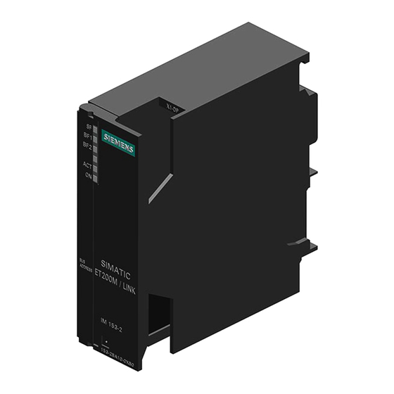
Page 25: Front View Of The Im 153-1 And Im 153-2Aa02/-2Ab01
... with fiber-optic ... with RS 48 cable interface 5 interface (IM 153-2 FO only) PROFI- PROFI- Status and fault Status and fault BUS-DP BUS-DP SIEMENS LEDs LEDs PROFIBUS-DP interface: Door 9-pin socket fiber-optic cable connection SIMATIC Cable pit ET 200M... -
Page 26: Front View Of The Im 153-2Bx00
Front View of the IM 153-2Bx00 Front door closed Front door open ... with fiber-optic ... with RS 48 cable interface(IM 5 interface 153-2 FO only) Status and fault LEDs SIEMENS PROFIBUS-DP interface: 9-pin socket fiber-optic cable connection Firmware version Door Cable pit compartment... - Page 27 Product Overview Distributed I/O Device ET 200M 1-12 EWA-4NEB780600602-06 Artisan Technology Group - Quality Instrumentation ... Guaranteed | (888) 88-SOURCE | www.artisantg.com...
-
Page 28: Getting Started
Getting Started Chapter Overview Section Subject Page Introduction Order Numbers for the Sample Configuration Prerequisites Installation Wiring Putting Hardware into Service Configuration Integration into the User Program 2-10 Switching On 2-10 2.10 Diagnostics 2-11 Distributed I/O Device ET 200M EWA-4NEB780600602-06 Artisan Technology Group - Quality Instrumentation ... -
Page 29: Introduction
Getting Started Introduction In this chapter the following simple sample configuration will show you step by step how to put the ET 200M into service. S Installation and wiring of the ET 200M S Configuration with STEP 7 S Integration into the user program S Switching on the ET 200M S Evaluation of the diagnostics: –... -
Page 30: Order Numbers For The Sample Configuration
Getting Started Order Numbers for the Sample Configuration Quan- Article Order number tity (Siemens) Rail e. g. 6ES7 390-1AE80-0AA0 Power supply PS 307 with jumper e. g. 6ES7 307-1BA00-0AA0 Interface module IM 153-2 6ES7 153-2BA00-0XB0 DI module SM 321 e. g. -
Page 31: Prerequisites
Getting Started Prerequisites S You have set up an S7 station consisting of a power supply module and a DP master (e.g. CPU 315-2 DP). In this sample configuration a CPU 315-2 DP is used as the DP master. It is, of course, possible to use a different DP master (IEC 61784-1:2002 Ed1 CP 3/1 standard). -
Page 32: Wiring
Getting Started Wiring Rail 1. Connect the rail to the protective conductor. An M6 screw is provided for this purpose on the rail. Minimum cross-section from the conductor to the protective conductor: 10 mm Warning: You could touch live wires if the power supply module PS 307 is switched on or the supply cable of the power supply is connected to the mains supply. -
Page 33: Wiring Of The Et 200M
Getting Started 4. Wire the front connector of the DI in the following way: Terminal 1: L+ of PS; Terminal 20: M of PS; Terminal 3: button 1; Terminal 4: button 2; Terminal 10: free cable ends of button (see Figure 2-3) 5. -
Page 34: Putting Hardware Into Service
Getting Started Putting Hardware into Service Step Activity Result Connect the programming device to the DP master (MPI interface) using the programming device cable. Make sure that the terminating resistors in the connectors are switched on. Set the mode switch to STOP. Connect the power supply cable to the The 24 V DC LED lights up on the PS. -
Page 35: Configuration
Getting Started Configuration 1. Start the SIMATIC Manager and create a new project with a DP master (e.g. CPU 315-2 DP). In addition to OB 1 also create OB 82 for the project. 2. Add the IM 153-2 from the hardware catalog to the PROFIBUS. 3. -
Page 36: Dp Slave Properties Dialog Box For Sm
Getting Started 5. Set the following parameters: – in the DP slave properties dialog box for ET 200M, accept the default settings – in the DP slave properties dialog box for SM 321, slot 4 in the configuration table Diagnostics: No load voltage yes Diagnostic alarm: yes –... -
Page 37: Integration Into The User Program
Getting Started Integration into the User Program 1. Create the user program in the LAD/STL/FBD editor in OB 1. Example: Reading in the inputs and activating an output Description U E 0.1 If input E 0.1 is set and U E 0.2 input E 0.2 is set, then = A 4.0 assign the RLO to output A 4.0... -
Page 38: Diagnostics
Getting Started 2.10 Diagnostics 1. If a fault occurs, the OB 82 is started. Evaluate the start information in the OB 82. Tip: Call SFC 13 within OB 82 and evaluate the diagnostic frame. (See Section 6.3) SM 321: Short Circuit of Sensor Power Supply to M 1. - Page 39 Getting Started SM 322: Short Circuit to L+ 1. Open the front door of the DO module and use a wire to short-circuit the digital output 0 (terminal 3) to L+ (terminal 1). 2. Watch the status LEDs. IM 153-2: –...
-
Page 40: Configuration Options With The Et 200M
Configuration Options with the ET 200M This chapter shows you when to use which IM 153-x for what purpose, and provides examples. Chapter Overview Section Subject Page Distributed I/Os with the IM 153-1 Forwarding Parameterization Data from the PG/PC with the IM 153-2 Parameterizable FM in a Configuration with an IM 153-2 Time Stamping with the IM 153-2 Redundancy with the IM 153-2... -
Page 41: Distributed I/Os With The Im
Configuration Options with the ET 200M Distributed I/Os with the IM 153-1 The IM 153-1 is the slave interface module of the ET 200M for standard applications. Figure 3-1 shows an example of an ET 200M with an IM 153-1 and 4 I/O modules of the S7-300 as distributed I/Os on a CPU 315-2 DP as S7-DP master. -
Page 42: Forwarding Parameterization Data From The Pg/Pc With The Im
Configuration Options with the ET 200M Forwarding Parameterization Data from the PG/PC with the IM 153-2 Sample Configuration with an IM 153-2 and a HART Module You can use HART modules in the ET 200M. In this application, the ET 200M is the HART master for HART slaves (intelligent field devices) in the explosion-proof area. -
Page 43: Parameterizable Fm In A Configuration With An Im 153-2
Configuration Options with the ET 200M Parameterizable FM in a Configuration with an IM 153-2 Sample Configuration with an IM 153-2 and FM Figure 3-3 shows an example of an ET 200M with an IM 153-2 and two SMs and two FMs of the S7-300 I/O modules. - Page 44 Configuration Options with the ET 200M Time Stamping with the IM153-2 Time stamping with IM 153-2 is possible S in customer applications which use FB 62 (FB TIMESTMP) (see online help for STEP 7) S with the PCS 7 system solution with accuracy of 10 ms A detailed description of time stamping with 10 ms accuracy and time synchronization can be found in the PCS 7 function manual ”10 ms Time Stamping”.
-
Page 45: Time Stamping With 10 Ms Accuracy
Configuration Options with the ET 200M 3.4.1 Time Stamping with 10 ms Accuracy The time stamping of signal changes is supported throughout the PCS 7 system by all the hardware and software components: from the IM 153-2 via an S7-400 to the Prerequisite The synchronization interval must be set to 10 seconds. -
Page 46: Sample Configuraton With 2 Im 153-2 For Redundancy In A
Configuration Options with the ET 200M In the Redundant System The IM 153-2 also supports the time stamp function in the redundant S7-400H system. Time Stamping Signal Changes in a S7-400H The two IM 153-2 modules store the messages of the time-stamped signals. This makes it possible, after a switchover operation from the active to passive IM 153-2, for the “new”... -
Page 47: Time Stamping With 3 Ms Accuracy
Configuration Options with the ET 200M 3.4.2 Time Stamping with 3 ms Accuracy Prerequisites The following configuration is permitted for time stamping with 3 ms accuracy: S IM 153-2 (as of 6ES7 153-2Bx00-0XB0) S DI modules – SM 321; DI 16 x 24 V DC; with diagnostics 6ES7 321-7BHx0-0AB0 The synchronization interval must be set to 10 seconds. -
Page 48: Redundancy With The Im 153-2
Configuration Options with the ET 200M Redundancy with the IM 153-2 You can operate the IM 153-2 with redundancy S on S7 DP masters (e.g. S7-400H) S on S5 DP masters (e.g. S5-115H) S with software redundancy S in accordance with the relevant standard (Specification System Redundancy (SR) V1.0, Dec. -
Page 49: Redundancy With 2 Im 153-2 Modules In An H System
Configuration Options with the ET 200M Sample Configuration of a Redundant DP Master System and the IM 153-2 Figure 3-6 shows an example of a configuration on an S7-400H. For the S7-400H, the ET 200M is a single-channel switched (distributed) I/O module. You will find a detailed description of H systems in the S7-400H Programmable Controller, Introduction to the System Manual. -
Page 50: Configuration Modification In Run
Configuration Options with the ET 200M S5-115H/155H as DP Master If you use the IM 153-2 on an S5-H system, you must configure two DP master systems in COM PROFIBUS. Power Supply of the IM 153-2 To safeguard availability in redundancy mode with 2 IM 153-2, we recommend you use a dedicated power supply module for each IM 153-2. - Page 51 Configuration Options with the ET 200M Configuration with Device Master File Principle With the IM 153-2Bx00, a configuration modification in RUN is also possible when configuring with device master file. In this case, modules are added to or removed from an ET 200M during operation. Existing modules and modules which are not to be modified are unaffected.
- Page 52 Configuration Options with the ET 200M Configuration modification procedure Reconfiguration is performed in the following way (example): 1. Make the appropriate modifications to the configuration offline (remove or add module). Note The parameters of a module can only be changed by making two configuration modifications in RUN: 1.
-
Page 53: Configuration Modification In Run In Non-Redundant System
Configuration Options with the ET 200M Attention It is the user’s responsibility to ensure that the configuration within the master system is uniform. The system does not indicate whether the two IM 153-2 modules are operating with different configurations. If the two masters in the redundant system have different configurations, a configuration modification in RUN is carried out whenever a switchover is performed. -
Page 54: Clock Synchronism
Configuration Options with the ET 200M Clock Synchronism Reproducible response times (i.e. response times with identical length) are implemented in the SIMATIC using the equidistant DP bus cycle, synchronization of the user program with the DP bus cycle, and clock-synchronized transmission of the I/O data to the I/O modules. - Page 55 Configuration Options with the ET 200M Prerequisites S Interface module IM 153-2; Order number 6ES7 153-2Bx00-0XB0 as of E01 S STEP 7 V5.2 or higher S PROFIBUS-DP must have a data transfer rate of at least 1.5 Mbaud (low equidistance times can be achieved using high baud rates). S The maximum equidistance cycle is 32 ms.
-
Page 56: Clock-Synchronized Interrupts" Dialog Box
Configuration Options with the ET 200M Procedure for Parameterizing Clock Synchronism 1. Settings at the CPU: ”Object Properties” of the CPU > ”Clock-Synchronized Interrupts” tab – Set CPU clock-synchronized interrupt. – Select the used DP master system. – Select the desired subprocess image. –... -
Page 57: Option" Dialog Box
Configuration Options with the ET 200M 2. Settings at the DP master system: ”Object Properties” of the DP master > ”General” tab > ”Properties” button > ”Parameters” tab > ”Properties” button > ”Network Settings” tab > ”Options” button – Activate the equidistance at the DP master system. –... -
Page 58: Dp Slave Properties" Dialog Box
Configuration Options with the ET 200M 3. Settings at the DP slave: ”Object Properties” of the DP slave> ”Clock Synchronization” tab – Activate ”Synchronize DP slave with equidistant DP cycle”. – Enter the times Ti and To (if not set at the master system under ”Times Ti and To identical for all DP slaves”). - Page 59 Configuration Options with the ET 200M Time Calculation Only the processes in the IM 153-2 interface module are taken into consideration in the formulae below. Times for data exchange and processes in the I/O modules are not taken into consideration. The values only apply to the system without active bus modules.
- Page 60 Configuration Options with the ET 200M Internal Processes of the IM 153-2 K [ms] + = 100 µs = 100 µs = 1, if time synchronization is active = 0 otherwise = 400 µs = 1, if parameterizable modules are used = 0 otherwise = 500 µs = 1, if I&C/HART modules or...
-
Page 61: Identification Data
Configuration Options with the ET 200M Identification Data Identification data is information stored in a module and supports the user when S eliminating faults in a system S checking the system configuration S locating hardware modifications in a system The identification data allows modules to be clearly and unambiguously identified online. -
Page 62: Structure Of Data Records With Identification Data
Configuration Options with the ET 200M 2. The item of identification data assigned to the respective index can be found under the associated data record number (see Table 3-3). – All data records with identification data have a length of 64 bytes. –... - Page 63 Index 1 Manufacturer Read 2A hex (= 42 dec) The name of the manufacturer is (2 bytes) stored here. (42 dec = Siemens AG) Device designation Read 6ES7 153-2Bx00-0XB0 Order number of the module (20 bytes) Device serial number Read...
-
Page 64: Fiber-Optic Network With The Im 153-2 Fo
Configuration Options with the ET 200M Fiber-Optic Network with the IM 153-2 FO In this section we show you a sample configuration of a fiber-optic network without considering the function performed by the IM 153-2 FO. Sample Configuration Figure 3-10 shows an example of how a fiber-optic network is configured with the ET 200M and the IM 153-2 FO as the slave interface. -
Page 65: Direct Communication
Configuration Options with the ET 200M 3.10 Direct Communication As of STEP 7 V 5.0 you can configure direct communication for the PROFIBUS nodes. The IM 153-x can participate in direct communication as the sender (publisher). Principle Direct communication is characterized by the fact that the PROFIBUS-DP nodes listen in to find out which data a DP slave is sending back to its DP master. -
Page 66: Installation
Installation Introduction In this chapter we will show you how to carry out the mechanical configuration, and prepare and install the ET 200M components. To set up an ET 200M, you must take into account the configuration of the electrical installation. Make sure you also read Chapter 5, entitled ”Wiring”. Chapter Overview Section Contents... -
Page 67: Mechanical Configuration
Installation Mechanical Configuration In This Section Section Subject Page 4.1.1 Horizontal and Vertical Installation 4.1.2 Clearance Measurements 4.1.3 Arrangement of the Modules in an ET 200M Configuration 4.1.4 Rules for Configuring the ”Module Change During Operation” and ”Redundancy” Functions 4.1.1 Horizontal and Vertical Installation You can install the ET 200M horizontally or vertically. -
Page 68: Clearance Measurements For An Et 200M Installation On A
Installation 4.1.2 Clearance Measurements Rules If you adhere to the minimum clearance measurements: S You will ensure that the S7-300 modules do not get too hot. S You will have adequate space for inserting and removing the S7-300 modules. S You will have sufficient space for running cables. S If you use a shield contact element, you can connect shielded cables directly with the rail (see Section 5.2.4). -
Page 69: Arrangement Of The Modules Of An Et 200M
Installation Length of the Rails Depending on the ET 200M installation you have, you can use the following rails: Rail for ... Usable length for Remarks modules ”Standard” Module change during operation 160 mm – 120 m Comes with fixing holes 482.6 mm 482.6 mm 450 mm... -
Page 70: Rules For Configuring The "Module Change During Operation" And "Redundancy" Functions
Installation Installation in an Intrinsically Safe Area If you use the ET 200M in intrinsically safe areas, you must insert a DM 370 dummy module between the IM 153-x and the modules in the intrinsically safe area. This is the only way to adhere to the required thread length (see also the Intrinsically Safe I/O Modules) Reference Manual. - Page 71 Installation S Use the rails for ”module change during operation” (only these can take the active bus modules). S Close unused slots with the backplane bus cover. Close the last bus module with the bus module cover. The bus module cover is included with the BM PS/IM and IM/IM bus modules.
-
Page 72: Installation Setup With Active Bus Modules
Installation Installation Options You can install up to 9 active bus modules depending on the length of the rail: You can use the following bus modules depending on functionality and installation setup: Redundancy with IM 153-x for ”module 2 IM 153-2 change during operation”... -
Page 73: Installation
Installation Installation There are two configuration types for the ET 200M: S Standard configuration with rail and bus connectors between the modules S Configuration with active bus modules for the ”Module Change During Operation” and/or ”Redundancy” functions You should read the sections which are relevant to your needs: Installing the Rail Standard Configuration Configuration with Active Bus Modules... -
Page 74: Fixing Holes Of The 2 M Rail
Installation Are you Installing a 2-Meter Rail? If not, you can skip this section and read on from the section entitled Dimensioned Drawing for Fixing Holes. If so, the 2-meter rail has to be prepared for installation. Proceed as follows: 1. -
Page 75: Fixing Holes For Rails
Installation Dimensioned Drawing for Fixing Holes The fixing-hole dimensions for the rail are shown in Table4-1. Table 4-1 Fixing holes for rails Din Rail 2 m Rail 32.5 32.5 mm 57.2 57.2 mm approx. approx. 500 mm 500 mm 15 mm Length of Rail Dimension a Dimension b... -
Page 76: Connecting The Protective Conductor To The Rail
Installation Installing the Rail To install the rail, proceed as follows: 1. Choose a position for the rail that leaves enough room to install it properly and enough space to cope with the temperature rise of the modules (leave at least 40 mm free above and below the rail;... -
Page 77: Standard Configuration (Installing Modules On The Rail)
Installation 4.2.2 Standard Configuration (Installing Modules on the Rail) Accessories The accessories you need for installation are included with the modules. Appendix A contains a list of accessories and spare parts with the corresponding order numbers. Table 4-2 Module accessories Module Accessories Included Description... -
Page 78: Installing The Modules On The Rail
Installation Sequence for Installation The individual steps to be followed when installing the modules are described below. Table 4-3 Installing the modules on the rail Steps Figure Attach and secure the PS 307 power supply. Each signal module comes with a bus connector, but not the IM 153-x. -
Page 79: Configuration With Active Bus Modules (Installing Active Bus Modules And Modules)
Installation 4.2.3 Configuration with Active Bus Modules (Installing Active Bus Modules and Modules) Installing Bus Modules and Modules To install the active bus modules and modules, proceed as follows: Only install the active bus modules in a de-energized state. 1. Hook the lower edge of the BM PS/IM or BM IM/IM bus module onto the rail, press it into the rail (a), and push it to the left until it engages (b). -
Page 80: After Installation
Installation Plugging in Output Modules During Operation of an ET 200M Installation Warning When you insert output modules, uncontrolled system states may occur. This is also the case when you plug in input/output modules at an angle onto the bus module. When you plug in an output module, the outputs set by the user program immediately become active! We recommend that you set the outputs in the user program to ”0”... -
Page 81: Applying Slot Numbers To The Modules
Installation Applying Slot Numbers Figure 4-7 shows you how to apply the slot numbers. The slot number labels are included with the IM 153-x. Figure 4-7 Applying slot numbers to the modules Distributed I/O Device ET 200M 4-16 EWA-4NEB780600602-06 Artisan Technology Group - Quality Instrumentation ... Guaranteed | (888) 88-SOURCE | www.artisantg.com... -
Page 82: Connecting The Bus Connector
Installation Connecting the Bus Connector The following bus connectors are available: S Up to 12 Mbaud – Without programming device socket (6ES7 972-0BA11-0XA0) – With programming device socket (6ES7 972-0BB11-0XA0) S Up to 12 Mbaud, angular outgoing cable – Without programming device socket (6ES7 972-0BA40-0XA0) –... -
Page 83: Connecting The Fiber-Optic Cable To The Im 153-2 Fo
Installation Connecting the Fiber-Optic Cable to the IM 153-2 FO Accessories Required: S Pack of Simplex connectors and polishing sets (6GK1 901-0FB00-0AA0) S Pack of plug-in adapters (6ES7 195-1BE00-0XA0) S Tool for removing the cable sheath (6GK1 905-6PA10) Installing Connectors 1. -
Page 84: Inserting The Fiber-Optic Cables Into The Im 153-2 Fo
Installation Reusing Fiber-Optic Cables Note If you insert used fiber-optic cables in the plug-in adapter again, you must cut off the bent lengths of both fiber-optic cable cores and install the Simplex connectors again. This avoids any attenuation losses due to parts of the cores of the fiber-optic duplex cables being bent again and overstressed. -
Page 85: Setting The Profibus Address
Installation Bending Radius for the Fiber-Optic Cable Make sure when you wire the fiber-optic duplex cable cores and insert them into the plug-in adapter, that the permissible bending radius of 30 mm is not exceeded. See also the installation guidelines on fiber-optic cables in the ET 200M Distributed I/O Device manual or the SIMATICNETPROFIBUSNetworks manual. - Page 86 Installation Setting the PROFIBUS Address Set the PROFIBUS address using a screwdriver and with the door open. The PROFIBUS address is the addition of the switches that are on the right (”ON” position). Note To allow the PROFIBUS address to be set, the IM 153-2Bx00 has an 8-pin DIP switch instead of the previously used 7-pin switch.
- Page 87 Installation Distributed I/O Device ET 200M 4-22 EWA-4NEB780600602-06 Artisan Technology Group - Quality Instrumentation ... Guaranteed | (888) 88-SOURCE | www.artisantg.com...
-
Page 88: Wiring
Wiring Introduction In this chapter we show you how to configure the electrical installation and how to wire an ET 200M. To set up an ET 200M, you must take into account the mechanical configuration. Make sure you also read Section 4.1. Basic Rules In view of the many and varied applications of an ET 200M, this chapter can only describe a few basic rules on its electrical configuration. -
Page 89: Electrical Configuration
Wiring Electrical Configuration Section Subject Page 5.1.1 General Rules and Regulations on Operating an ET 200M 5.1.2 Operating the ET 200M with Process I/O Modules on a Grounded Supply 5.1.3 Configuring the ET 200M with Ungrounded Reference Potential 5.1.4 Configuring the ET 200M with Galvanically Isolated Modules 5-10 5.1.5 Configuring the ET 200M with Non-Isolated Modules... - Page 90 Wiring Note on Radio Interference When several electronic components are used within a switch cabinet, the radio interference can overlap. As a result, the permissible level of radio interference intensity in the overall configuration may be exceeded. Tip: Space these modules out as much as possible and, if necessary, use shielded cables or filters in the supply lines or switch cabinets with greater resistance to radio frequency.
- Page 91 Wiring Protection From External Electrical Exposure The following table shows you what to remember about protection from electrical exposure and faults. With ... Make Sure That ... All plants or systems in ... the plant or system is connected to the protective which the ET 200M is conductor for diverting electromagnetic interference.
-
Page 92: Operating The Et 200M With Process I/O Modules On A Grounded Supply
Wiring 5.1.2 Operating the ET 200M with Process I/O Modules on a Grounded Supply This section contains information concerning the overall configuration of an ET 200M system with a grounded incoming supply (TN-S system). The specific subjects discussed are: S Circuit-breaking devices, short-circuit and overload protection in accordance with DIN VDE 0100 and DIN VDE 0113 S Load power supplies and load circuits. - Page 93 Safe (electrical) isola- Modules that have to be The PS 307 power supplies and the supplied with v60V DC tion Siemens load power supplies of the or v25V AC 6EP1 series have this feature. 24V DC load circuits Output voltage toleran-...
-
Page 94: S7-300 Modules Operated On A Grounded Incoming Supply
Wiring ET 200M in the Overall Configuration Figure 5-1 shows you the position of the ET 200M in the overall configuration (load power supply and grounding concept) with power infeed from a TN-S system. Note: The illustration of the power supply connections does not reflect the actual physical arrangement;... -
Page 95: S7-300 Modules Operated From The Ps
Wiring ET 200M with Load Power Supply from the PS 307 Figure 5-2 shows the ET 200M in the overall configuration (load power supply and grounding concept) in a TN-S system. In addition to supplying the IM 153-x, the PS 307 also supplies the load circuit for the 24V DC modules. -
Page 96: Configuring The Et 200M With Ungrounded Reference Potential
Wiring 5.1.3 Configuring the ET 200M with Ungrounded Reference Potential When the ET 200M is configured with ungrounded reference potential, any interference current is diverted to the protective conductor via an RC network integrated in the IM 153-x (see Figure 5-3). See also Section 9.3 for older IM 153-x versions. -
Page 97: Configuring The Et 200M With Galvanically Isolated Modules
If you supply the IM 153-x from a battery without grounding the reference potential, you must suppress interference on the 24 V DC supply. Use an interference suppression device from Siemens such as B84102-K40. Insulation Monitoring If dangerous plant conditions can arise as a result of double faults, you must provide some form of insulation monitoring. -
Page 98: Simplified Illustration Of The Configuration With Isolated Modules
Wiring Configuration with Isolated Modules Figure 5-4 shows the potentials of an ET 200M configuration with isolated input/output modules. IM 153-x Data Ground bus in cabinet 230V AC load 24V DC load current supply current supply Figure 5-4 Simplified illustration of the configuration with isolated modules Distributed I/O Device ET 200M 5-11 EWA-4NEB780600602-06... -
Page 99: Configuring The Et 200M With Non-Isolated Modules
Wiring 5.1.5 Configuring the ET 200M with Non-Isolated Modules Potentials in a Configuration with Non-Isolated Modules Figure 5-5 shows the potentials of an ET 200M configuration with grounded reference potential with the non-isolated analog input/output module SM 334; AI 4/AO 2 8/8Bit. -
Page 100: Wiring
Wiring Wiring In This Chapter Section Subject Page 5.2.1 Wiring Rules 5-13 5.2.2 Wiring the Power Supply Module and IM 153-x 5-15 5.2.3 Wiring the Front Connectors of the Signal Modules 5-17 5.2.4 Connecting Shielded Cables via a Shield Contact Element 5-21 5.2.1 Wiring Rules... -
Page 101: Wiring Rules For Module Front Connectors
Wiring Table 5-3 Wiring rules for module front connectors Wiring Rules for ... Wiring Rules for ... Module Front Connectors (Screw-Type Module Front Connectors (Screw-Type Terminal and Spring Terminal) 20-pin 40-pin Connectable wire cross-sections for rigid lines Connectable wire Without wire end 0.25 to 1.5 mm 0.14 to 0.75 mm cross-sections for... -
Page 102: Wiring The Power Supply And Im 153-X
Wiring 5.2.2 Wiring the Power Supply and IM 153-x Power Cables To wire the power supply, use flexible cables (see Table 5-2 on page5-13). If you use only one cable per connection, you don’t need an end ferrule. Jumper Use the jumper when wiring the PS 307 power supply module to the IM 153-x. The jumper comes with the power supply module. -
Page 103: Wiring The Ps 307 Power Supply Module And The Im 153-X With
Wiring Wiring with the Jumper To wire the power supply module and IM 153-x, proceed as follows (see Figure 5-6). Warning Make sure the ET 200M is de-energized before doing any wiring! 1. Open the front doors of the PS 307 and IM 153-x. 2. -
Page 104: Wiring The Front Connectors Of The Signal Modules
Wiring 5.2.3 Wiring the Front Connectors of the Signal Modules S7 Explosion-Proof Modules You can find out how to wire the S7 explosion-proof modules and what to look out for when wiring modules in an intrinsically safe area in the Intrinsically Safe I/O Modules Reference Manual. -
Page 105: Bringing The Front Connector Into The Wiring Position
Wiring Preparing the Connector for Wiring To prepare for wiring, proceed as follows: Warning Accidental contact with live conductors is possible, if the power supply module and any additional load power supplies are switched on. Make sure the ET 200M is de-energized before doing any wiring! 1. -
Page 106: Wiring The Front Connector
Wiring Wiring the Front Connector Table 5-4 Wiring the front connector Step 20-Pin Front Connector 40-Pin Front Connector Thread the cable strain-relief assembly – into the front connector. Do you want to bring the cables out at the bottom of the module? If so: Start with terminal 20, and wire the Starting at terminal 40 or 20, wire the... -
Page 107: Preparing The Signal Module For Operation
Wiring Preparing the Signal Module for Operation Table 5-5 Preparing the signal module for operation Step 20-Pin Front Connector 40-Pin Front Connector Press down the unlocking button on the Tighten screws to bring front connector top of the module and, at the same time, to its operating position. -
Page 108: Connecting Shielded Cables Via A Shield Contact Element
Wiring 5.2.4 Connecting Shielded Cables via a Shield Contact Element Introduction This section tells you how to connect the shield of shielded signal lines to ground via a shield contact element. The connection to ground is achieved by direct contact between the shield contact element and the rail. Application You can do the following easily with the shield contact element: S Connect all S7-300 module shielded cables to ground... -
Page 109: Attaching Shielded 2-Wire Cables To A Shield Contact Element
Wiring Installing the Shield Contact Element Install the shield contact element as follows: 1. Push the two bolts of the fixing bracket into the guide on the underside of the rail. Position the fixing bracket under the modules to be wired. 2. -
Page 110: Commissioning And Diagnostics
Commissioning and Diagnostics Chapter Overview Section Subject Page Commissioning and Startup of the DP Slave Diagnostics Using LEDs 6-10 Diagnostics Using STEP 7 and STEP 5 6-13 Structure of the Diagnosis 6-16 Commissioning and Startup of the DP Slave This section describes the prerequisites for commissioning and the few steps that need to be taken to commission the ET 200M. -
Page 111: Prerequisites For Commissioning
DP master used 1 The functions which can be operated with the individual device master file revisions are listed in Table 6-4. You can find the current device master file on the Internet at http://www.ad.siemens.de/csi_e/gsd. Distributed I/O Device ET 200M EWA-4NEB780600602-06... -
Page 112: Commissioning Prerequisites For The Dp Slave
Commissioning and Diagnostics Prerequisites for Commissioning Table 6-2 Commissioning prerequisites for the DP slave Required Activity DP Interface See ... RS 485 1. DP slave installed Section 4.2 2. PROFIBUS address set on the DP slave Section 4.5 3. Bus connector and fiber-optic cable connected Section 4.3 and 4.4 4. -
Page 113: Startup Of The Im
Commissioning and Diagnostics 6.1.2 Startup of the IM 153-1 Switch on the supply voltage for the DP slave The ”ON” and ”BF” LEDs come on DP slave sets outputs to ”0” and accepts the set PROFIBUS address DP slave receives configuration data from the DP master Does the configuration Desired... -
Page 114: Startup Of The Im 153-2/153-2 Fo
Commissioning and Diagnostics 6.1.3 Startup of the IM 153-2/153-2 FO The designation IM 153-2 in this section applies to both the IM 153-2 and the IM 153-2 FO. Agreement in the case of Redundancy: In the case of redundancy, the two inserted IM 153-2 modules operate independently of one another. - Page 115 Commissioning and Diagnostics Switch on the supply voltage for the IM 153-2 (a) IM 153-2Bx00 only: All LEDs light up for a few seconds during internal tests The ”ON” and ”BF” LEDs come on IM 153-2 (a) checks Startup as in No configuration whether it is inserted Figure 6-1 on...
-
Page 116: Startup For Time Synchronization/Time Stamping
Commissioning and Diagnostics Startup for Time Synchronization/Time Stamping of Signal Changes Startup is completed as in Figure 6-3. The IM 153-2 is ready for data transfer with the DP master. Clock in the IM 153-2 Read time frame Are suitable time stamping parameters Set the IM 153-2 clock available... -
Page 117: Profibus-Dpv1 Mode
Commissioning and Diagnostics 6.1.4 PROFIBUS-DPV1 Mode The ET 200M fulfills the requirements of DPV1. If you want to use the DPV1 functions, the DP master must of course also fulfill the requirements of DPV1 (see the documentation for the DP master). The table below shows you the new functions of the PROFIBUS-DPV1 slave compared to a PROFIBUS-DPV0 slave: Table 6-4... - Page 118 Commissioning and Diagnostics Actions Following Diagnostic Message in S7 or DPV1 Mode Every diagnostic message triggers the following actions: S In S7 or DPV1 mode, diagnoses are reported as diagnostic interrupts. S In DPV1 mode, diagnoses are also reported when the master CPU is in STOP mode.
-
Page 119: Diagnostics Using Leds
Check the SM/FM with the diagnosis. There is an error or diagnosis in an Change the S7-300 module or the IM S7-300 module 153-1 or contact your Siemens partner. If not: The IM 153-1 is defective. Data transfer is taking place between the –... -
Page 120: Status And Error Messages Of The Im
Commissioning and Diagnostics IM 153-2 Table 6-6 Status and error messages of the IM 153-2 IM 153-2AA02/-2AB01 IM 153-2Bx00 SF (group fault): BF (fault at PROFIBUS): ACT (active module in redundancy mode): yellow ON (supply voltage available): green LEDs Meaning What to Do ACT ON There is no voltage applied to the... - Page 121 Is the SF LED of an SM/FM also on? Change the S7-300 module or the IM If so: There is an error or a diagnosis 153-2 or contact your Siemens in an S7-300 module partner. If not: The IM 153-2 is defective.
-
Page 122: Diagnostics Using Step 7 And Step
Commissioning and Diagnostics Diagnostics Using STEP 7 and STEP 5 Slave Diagnostics The slave diagnostics performs to the standard IEC 61784-1:2002 Ed1 CP 3/1. Depending on the DP master, the diagnostics can be displayed for all DP slaves which perform to standard, using STEP 7 or STEP 5. Displaying and structuring the slave diagnostics is described in the following sections. - Page 123 Commissioning and Diagnostics Example of Displaying the S7 Diagnosis Using SFC 13 ”DPNRM_DG” Here you will find an example of how to use SFC 13 to display the slave diagnosis for a DP slave in the STEP 7 user program. Assumptions The following assumptions apply to this STEP 7 user program: S The diagnostic address of the ET 200M is 1022 (3FE...
- Page 124 Commissioning and Diagnostics Example of Displaying the Slave Diagnosis with FB 192 ”IM308C” Here you will find an example of how to use the FB 192 to display the slave diagnosis for a DP slave in the STEP 5 user program. Assumptions The following assumptions apply to this STEP 5 user program: S The IM 308-C is assigned pages 0 to 15 (number 0 of the IM 308-C) as the DP...
- Page 125 Commissioning and Diagnostics Structure of the Diagnosis Introduction The IM 153-x makes the standard slave diagnosis available to you. Note the differences in the diagnostic frame depending on which version of IM 153-x and which release you have. Depending on the DP master and parameter assignment, the following can provide an enhanced diagnosis: IM 153-1 as of 153-1AA03, version 02, DDB version V1.18;...
-
Page 126: Structure Of The Slave Diagnosis
Commissioning and Diagnostics 6.4.1 Structure of the Slave Diagnosis Notes on Enhanced Diagnosis To use channel-specific diagnosis, you must enable the diagnostic interrupt in each I/O module using parameter assignment. When you parameterize the IM 153-x, you can enable or disable the diagnostic, process and insert/remove module interrupts regardless of whether or not the enhanced diagnosis is enabled. -
Page 127: Structure Of The Slave Diagnosis
Commissioning and Diagnostics Structure of the Slave Diagnosis Byte 0 Byte 1 Station statuses 1 to 3 Byte 2 Byte 3 Master PROFIBUS address High byte Byte 4 Manufacturer ID Byte 5 Low byte Enhanced diagnostics Byte 6 Module diagnosis Byte 8 Byte x IM 153-1AAx3... -
Page 128: Station Statuses 1 To
Commissioning and Diagnostics 6.4.2 Station Statuses 1 to 3 Definition Station statuses 1 to 3 provide an overview of the status of a DP slave. Station Status 1 Table 6-8 Structure of station status 1 (Byte 0) Meaning Cause/Remedy 1: The DP slave cannot be addressed Correct PROFIBUS address set on the DP by the DP master. -
Page 129: Structure Of Station Status 2 (Byte 1)
Commissioning and Diagnostics Table 6-8 Structure of station status 1 (Byte 0), continued Meaning Cause/Remedy 1: The DP slave type does not corres- Compare the desired configuration with the pond to the software configuration. actual configuration. 1: Parameters have been assigned to The bit is always 1 when you are accessing the DP slave by a different DP ma- the DP slave using the programming device... -
Page 130: Master Profibus Address
Commissioning and Diagnostics 6.4.3 Master PROFIBUS Address Definition The master PROFIBUS address diagnostic byte contains the PROFIBUS address of the DP master that: S Assigned parameters to the DP slave and S Has read and write access to the DP slave The master PROFIBUS address is in byte 3 of the slave diagnostics. -
Page 131: Structure Of The Module Diagnosis
Commissioning and Diagnostics 6.4.5 Module Diagnosis Definition The module diagnosis indicates whether or not modules of the ET 200M have errors/faults. The module diagnosis begins as of byte 6 and comprises 3 bytes. Module Diagnosis The module diagnosis for the ET 200M is structured as follows: Bit no. -
Page 132: Structure Of The Module Status For The Et 200M
Commissioning and Diagnostics 6.4.6 Module Status Definition The module status indicates the status of the configured modules and expands on the module diagnosis as regards the configuration. The module status begins after the module diagnosis and comprises 7 bytes. The module status is only contained in the diagnostic frame if you have enabled enhanced diagnosis during parameter assignment. -
Page 133: Channel-Specific Diagnosis
Commissioning and Diagnostics 6.4.7 Channel-Specific Diagnosis Definition The channel-specific diagnosis gives information on channel errors of modules and expands on the module diagnosis. The channel-specific diagnosis begins after the module status or after the H status. (see Section 6.4.8) The channel-specific diagnosis does not affect the module status. Important: The diagnostic interrupt must be switched on for each module! Channel-Specific Diagnosis The channel-specific diagnosis is only contained in the diagnostic frame if you... -
Page 134: Structure Of The Channel-Specific Diagnosis
Commissioning and Diagnostics 6 5 4 Bit no. as of Byte 16 000001 to 001010 : ID number of the module that delivers the channel-specific diagnosis. (Example: Slot 4 has ID no. 3; Slot 5 has ID no. 4) Code for channel-specific diagnosis 6 5 4 Bit no. -
Page 135: Channel-Specific Error Messages To Profibus Standard
Commissioning and Diagnostics Channel-Specific Error Messages Table 6-12 Channel-specific error messages to PROFIBUS standard Error Type Error Text Meaning What to Do 00001 Short circuit Short circuit because, for example: Correct the process wiring Sensor wiring to P potential short-circuited Sensor wiring to M potential short-circuited Output wiring to P potential short-circuited Output wiring to ground short-circuited... -
Page 136: Channel-Specific Error Messages - Manufacturer-Specific
Commissioning and Diagnostics Table 6-13 Channel-specific error messages – manufacturer-specific Error Type Error Text Meaning What to Do 10000 Parameter Parameter assignment error, for example, because: Correct the assignment parameter The module cannot use the parameter error assignment (unknown, impermissible combination...) Module is not parameterized 10001 Sensor or... -
Page 137: H Status (With S7-400H And Standard Redundancy Only)
Commissioning and Diagnostics 6.4.8 H Status (with S7-400H and Standard Redundancy Only) The IM 153-2 only delivers the H status if it is running on an S7-400H-DP master or is operating with redundancy to standard. 0 0 1 Byte z Length of the H status incl. -
Page 138: Interrupts
Commissioning and Diagnostics 6.4.9 Interrupts Definition The interrupts section of the slave diagnosis provides information on the type of interrupt and the cause that triggered the interrupt. The interrupt section has a maximum of 29 bytes. A maximum of one interrupt can be used per slave diagnosis. Position in the Diagnostic Frame The position of the interrupt section in the slave diagnosis depends on the structure of the diagnostic frame and on the number of channel-specific diagnoses... - Page 139 Commissioning and Diagnostics Removal and Insertion Interrupts To remove and insert modules during operation, you must configure the ET 200M with active bus modules (see Section 4.1.4 in the manual). Use the switch for the removal/insertion interrupt to parameterize whether removal/insertion events are to be reported as interrupts in the diagnostic frame.
-
Page 140: Structure Of The Interrupt Status Of The Interrupt Section
Commissioning and Diagnostics Interrupts The interrupt section for the ET 200M is structured as follows (in the IM 153-x without module status and channel-specific diagnosis, byte x = byte 9): Bit no. Byte x Length of the interrupt section including byte x Code for station diagnosis Byte x+1 Type of interrupt:... -
Page 141: Structure Of Bytes X+4 To X+7 For Diagnostic Interrupt
Commissioning and Diagnostics Diagnostic Interrupt, Bytes x+4 to x+7 Bytes x+4 to x+7 correspond to the diagnostic data record 0 in STEP 7.The bytes as of byte x+8 to byte x+19 correspond to diagnostic data record 1 in STEP 7. Byte x+4 Module malfunction, i. -
Page 142: Structure As Of Byte X+8 For Diagnostic Interrupt (Digital Inputs)
Commissioning and Diagnostics Diagnostic Interrupt of Modules with Digital Inputs Byte x+4 See Figure 6-11 on page 6-32 Byte x+7 : Module with digital inputs Byte x+8 Byte x+9 Length of the channel-specific diagnosis Byte x+10 Number of channels per module Byte x+11 Diagnostic event on the channel/channel group 0 of the module Diagnostic event on the channel/channel group 1 of the module... -
Page 143: Structure As Of Byte X+8 For Diagnostic Interrupt (Digital Outputs)
Commissioning and Diagnostics Diagnostic Interrupt of Modules with Digital Outputs Byte x+4 See Figure 6-11 on page 6-32 Byte x+7 : Module with digital outputs Byte x+8 Length of the channel-specific diagnosis Byte x+9 Number of channels per module Byte x+10 Byte x+11 Diagnostic event on the channel/channel group 0 of the module Diagnostic event on the channel/channel group 1 of the module... -
Page 144: Structure As Of Byte X+8 For Diagnostic Interrupt (Analog Inputs)
Commissioning and Diagnostics Diagnostic Interrupt of Modules with Analog Inputs Byte x+4 See Figure 6-11 on page 6-32 Byte x+7 : Module with analog inputs Byte x+8 : Module with HART analog inputs Length of the channel-specific diagnosis Byte x+9 Byte x+10 Number of channels per module Byte x+11... -
Page 145: Structure As Of Byte X+8 For Diagnostic Interrupt (Analog Outputs)
Commissioning and Diagnostics Diagnostic Interrupt of Modules with Analog Outputs Byte x+4 See Figure 6-11 on page 6-32 Byte x+7 : Module with analog outputs Byte x+8 Length of the channel-specific diagnosis Byte x+9 Byte x+10 Number of channels per module Byte x+11 Diagnostic event on the channel/channel group 0 of the module Diagnostic event on the channel/channel group 1 of the module... -
Page 146: Structure As Of Byte X+4 For Process Interrupt (Analog Inputs)
Commissioning and Diagnostics Process Interrupt of Analog Input Modules Byte x+4 Upper limit violation on channel 0 of the module Upper limit violation on channel 1 of the module Upper limit violation on channel 7 of the module Byte x+5 Lower limit violation on channel 0 of the module Lower limit violation on channel 1 of the module Lower limit violation on channel 7 of the module... -
Page 147: Evaluating Interrupts From The Station Diagnosis
Commissioning and Diagnostics Module Removal/Insertion Interrupt The module ID that was removed or inserted is in byte x+4 to x+8. You can find the IDs for the individual modules in the device master file. You can tell whether the module was removed or inserted by the type of interrupt in byte x+1 (see Figure 6-11, on page 6-32). - Page 148 Commissioning and Diagnostics Removal/Insertion Interrupt with S7/M7-DP Master or DPV1 Master If you use the ET 200M with ”module change during operation” on an S7/M7-DP master or a DPV1 master, the system behaves as follows: S When a module is removed, the IM 153-x reports a module removal interrupt on the DP master that executes OB 83.
- Page 149 Commissioning and Diagnostics Interrupts with Another DP Master If you operate the ET 200M with another DP master, these interrupts are simulated as a device-specific diagnosis of the ET 200M. You must postprocess the relevant diagnostic events in the DP master’s user program. Saving the Diagnosis Depending on byte x+1, transfer the contents of the station diagnosis to a data block because:...
-
Page 150: Maintenance
Maintenance Maintenance The ET 200M is a maintenance-free DP slave. Chapter Overview In this chapter you will find out how to replace modules or components. Section Subject Page Replacing the Power Supply Module Replacing the IM 153-1 Replacing the IM 153-2 or IM 153-2 FO Replacing Modules without the ”Module Change During Operation”... - Page 151 Maintenance Removing the Power Supply Module To remove the power supply module, proceed as follows: 1. Operate the supply isolating switch in order to de-energize the power supply module. 2. Remove the cover. 3. Disconnect all the wiring. 4. Undo the fixing screws of the power supply module. 5.
-
Page 152: Replacing The Im
Maintenance Replacing the IM 153-1 Initial Situation The IM 153-1 is installed. You want to install a new IM 153-1 of the same type. Slot Numbering If you have given slot numbers to the modules in your system, you must remove the numbering from the old module when you replace the module and use it on the new module. -
Page 153: Replacing The Im 153-2 Or Im 153-2 Fo
Maintenance Installing a New Module Install the new module as follows: 1. Set the same DP address on this IM 153-1 as for the old IM 153-1. 2. Hook the new IM 153-1 onto the rail and swing it down into place. 3. - Page 154 Maintenance IM 153-2: Unplugging the Bus Connector With a looped-through interconnecting cable you can unplug the bus connector from the PROFIBUS-DP interface without interrupting data traffic on the network. Note A data communication error may occur on the network. A network segment must always be terminated at both ends with the terminating resistor.
- Page 155 Maintenance In the Case of Redundancy Note Only replace the IM 153-2/-2 FO in a de-energized state! If you carry out a replacement in an energized state, the specified switchover times cannot be guaranteed and the I/O modules could fail for a certain time and output “0”.
- Page 156 If after replacement, the replaced IM 153-2/-2 FO goes into STOP (all the LEDs flash), the releases are not compatible. In this case you must switch off the ET 200M and upgrade the two IM 153-2/-2 FO or use a compatible version. Contact your Siemens partner. Distributed I/O Device ET 200M EWA-4NEB780600602-06...
-
Page 157: Replacing Modules Without The "Module Change During Operation" Function
Maintenance Replacing Modules without the ”Module Change During Operation” Function Removing a Module Table 7-1 Removing modules without ”module change during operation” Step 20-Pin Front Connector 40-Pin Front Connector Switch off the load voltage to the module. Switch off the power supply for the IM 153-x. Remove the labeling strip from the module. -
Page 158: Removing The Front Connector Coding Key
Maintenance Removing the Front Connector Coding Key Prior to installing the new module, you must remove the front connector coding key from the new module. Reason: This part is already in the wired front connector (see Figure 7-1). Figure 7-1 Removing the front connector coding key Installing a New Module Table 7-2... - Page 159 Maintenance Putting a New Module into Service Table 7-3 Putting new modules into service Step Putting a Module into Service Open the front door. Bring the front connector back into its operating position. Close the front door. Switch on the power supply for the IM 153-x. Switch the load voltage back on.
-
Page 160: Replacing Modules With The "Module Change During Operation" Function
Maintenance Replacing Modules with the ”Module Change During Operation” Function Prerequisites You can replace the modules during operation of the ET 200M once you have done the following: S Installed the ET 200M on the rail with active bus modules for the ”module change during operation”... - Page 161 Maintenance Removing the Front Connector Coding Key Prior to installing the new module, you must remove the front connector coding key from the new module. Reason: This part is already in the wired front connector (see Figure 7-17-9). Installing a New Module Table 7-5 Installing new modules Step...
-
Page 162: Replacing The Bus Module
Maintenance Replacing the Bus Module Removing the Bus Module Only remove bus modules if they are de-energized! Table 7-7 Removing the bus module Step Removing the Bus Module Put the on/off switch of the power supply module into the 0 position ( : output voltage 0 V). -
Page 163: Changing Fuses In Digital Output Modules
Maintenance Changing Fuses in Digital Output Modules Fuses for Digital Outputs Fuses are used for the individual channel groups of the digital outputs of the following digital output modules, to protect these against short circuit: S SM 322 DO 16 120V AC digital output module S SM 322 DO 8 120/230V AC... - Page 164 Maintenance Changing Fuses The fuses are located at the left side of the module. 1. Remove the digital output module as described in Section 7.4 2. Remove the fuse holder from the digital output module. 3. Replace the fuse. 4. Screw the fuse holder back into the digital output module. 5.
-
Page 165: Update Of The Im 153-X
Maintenance Update of the IM 153-x 7.8.1 Update of the IM 153-1/-2Ax0x Please contact your SIEMENS partner if you require an update of the IM 153-1 and IM 153-2Ax0x. 7.8.2 Update of the IM 153-2Bx00 When Should You Update the IM 153-2? You should update the interface module IM 153-2 to the latest firmware version following (compatible) function-related expansions or performance improvements. - Page 166 Maintenance Prerequisites For update via PROFIBUS-DP S The IM 153-2 in the station which is to be updated must be accessible online. S The files with the current (new) version of the firmware must be available in the file system of your PG/PC. For update via MMC S The update files must be available on the MMC.
- Page 167 Maintenance Sample Configuration Update from the PG/PC via PROFIBUS-DP (Direct) The PG/PC with the update files is connected directly to the PROFIBUS interface of the IM 153-2 (see Figure 7-3). Note If no STEP 7 project containing the IM 153-2 concerned is available, the update can also be performed using the online view (Accessible Nodes) in STEP 7.
- Page 168 Maintenance Update via MMC You perform an update via MMC in the following way: Table 7-8 Update via MMC Step You must do this: This happens at the IM 153-2: Transfer the update files to an MMC – using STEP 7 and your programming device.
-
Page 169: Update Via Mmc
Maintenance Update in the Redundant System If the update of the active IM 153-2 is performed via PROFIBUS-DP, the reset which is performed afterwards automatically triggers the switchover between the two IM 153-2 modules. We recommend that you then also update the second IM 153-2 in the redundant system. -
Page 170: Technical Specifications
Technical Specifications In This Chapter You will find the following: S The standards, certificates and approvals for the ET 200M. S The technical specifications of the IM 153-x slave interface. S The dimensioned drawing of the IM 153-x slave interface. S The basic circuit diagram of the IM 153-x slave interface. -
Page 171: Standards, Certificates And Approvals
S 94/9/EC ”Devices and Protection Systems for Specified Application in Hazardous Areas” (Explosion Protection Directive) The EC declarations of conformity are being kept available for the cognizant authorities at: Siemens Aktiengesellschaft Automation and Drives Group A&D AS RD4 Postfach 1963... - Page 172 Technical Specifications UL Approval Underwriters Laboratories Inc. to S UL 508 (Industrial Control Equipment) CSA Approval Canadian Standards Association to S C22.2 No. 142 (Process Control Equipment) Underwriters Laboratories Inc. to S UL 508 (Industrial Control Equipment) S CSA C22.2 No. 142 (Process Control Equipment) Underwriters Laboratories Inc.
- Page 173 Technical Specifications FM Approval Factory Mutual Research (FM) to Approval Standard Class Number 3611, 3600, 3810 APPROVED for use in Class I, Division 2, Group A, B, C, D Tx; Class I, Zone 2, Group IIC Tx to EN 50021 (Electrical apparatus for potentially explosive atmospheres; Type of protection ”n”) II 3 G EEx nA II T5 Marking for Australia...
- Page 174 Technical Specifications Ship-Building Approval Classification organizations: S ABS (American Bureau of Shipping) S BV (Bureau Veritas) S DNV (Det Norske Veritas) S GL (Germanischer Lloyd) S LRS (Lloyds Register of Shipping) S Class NK (Nippon Kaiji Kyokai) Use in Industrial Environments SIMATIC products are designed for use in industrial environments.
- Page 175 Technical Specifications Laser Safety Class Certification (for IM 153-2 FO) Class 1 to EN 60825-1: 1994+A11: 1996 and IEC 60825-1: 1993 incl. Amendment 1:1997 The radiant power emitted when the fiber-optic cable is opened intentionally or unintentionally corresponds to hazard potential 1 to EN 60825-2: 1994 and IEC 60825-2: 1993 Distributed I/O Device ET 200M EWA-4NEB780600602-06...
-
Page 176: Parameters Of The Im 153-X
Technical Specifications Parameters of the IM 153-x Parameter Assignment Assign parameters to the IM 153-x and the ET 200M with STEP 7 or COM PROFIBUS. If you use another configuration tool, you must integrate the device master file. Table 8-2 Parameters of the IM 153-x Parameters Value Range... - Page 177 Technical Specifications Parameters for Time Stamping Assign parameters for time stamping with STEP 7 for the ET 200M in the DP slave properties and also for each digital input module in the module properties. Table 8-3 Parameters for time stamping Parameters Value Range Default...
-
Page 178: Technical Specifications
Technical Specifications Technical Specifications General Technical Specifications In the Module Specifications Reference Manual you can find the following for the IM 153-x: S General technical specifications that are valid for the S7-300 and ET 200M system. S Deviating technical specifications and tests for the IM 153-1 for the extended range of environmental conditions (”outdoor”) (order number 6ES7 153-1AA8x-0XB0). - Page 179 Technical Specifications Technical Specifications IM 153-1 IM 153-2 IM 153-2 F0 Time Synchronization/Time Stamping Accuracy class – 10 ms/3 ms Time resolution – 1 ms Number of digital input – max. 128; signals Message buffer – 15 message buffers with a maximum of 20 messages each Time interval for sending –...
-
Page 180: Dimensioned Drawing Of The Im 153-1 And Im
Technical Specifications Dimensioned Drawing of the IM 153-1/-2/-2 FO You can find a dimensioned drawing of the rail for the active bus modules in the Module Specifications Reference Manual. 160 with front door open Figure 8-1 Dimensioned drawing of the IM 153-1 and IM 153-2 Basic Circuit Diagram of the IM 153-1/-2/-2 FO PROFIBUS-DP Logic... -
Page 181: Response Time Of The Et 200M
Technical Specifications Time Delay of the ET 200M Response Time – A Definition The response time is the time between detection of the input signal and the modification of the associated output signal. Duration The response time depends on the bus configuration and on the DP master. You can find fundamentals for calculating the response time in the DP master manuals. - Page 182 Technical Specifications Switchover Time in the Case of Redundancy The switchover time depends on the operating mode and the configuration: DP Master ET 200M Switchover Time Configuration System with IM 153... S7-400H -2AA02 70 ms Any configuration -2AB01 30 ms ...
- Page 183 Peripheriegerätes ET 200M und der SIMATIC S7-300 im explosionsgefährdeten Bereich. Weitere Informationen Weitere Informationen zum ET 200M und zu den verschiedenen S7-300- Baugruppen finden Sie im Handbuch. Fertigungsort Siemens AG, Bereich A&D Werner-von-Siemens-Straße 50 92224 Amberg Germany Zulassung II 3 G EEx nA II T3 ..
- Page 184 Diese Warnung kann unberücksichtigt bleiben, wenn bekannt ist, dass keine explosionsgefährdete Atmosphäre herrscht. Liste der zugelassenen Baugruppen Die Liste mit den zugelassenen Baugruppen finden Sie im Internet: http://www4.ad.siemens.de/view/cs/ unter der Beitrags-ID 13702947. Distributed I/O Device ET 200M EWA-4NEB780600602-06 Artisan Technology Group - Quality Instrumentation ... Guaranteed | (888) 88-SOURCE | www.artisantg.com...
- Page 185 I/O device and the SIMATIC S7-300 in a hazardous area. Further Information You will find further information on the ET 200M and the various S7-300 modules in the manual. Production Location Siemens AG, Bereich A&D Werner-von-Siemens-Straße 50 92224 Amberg Germany Certification II 3 G EEx nA II T3 ..
- Page 186 (i.e. there is no risk of explosion). List of Approved Modules You will find the list of approved modules under the ID 13702947 on the Internet: http://www4.ad.siemens.de/view/cs/ Distributed I/O Device ET 200M EWA-4NEB780600602-06 Artisan Technology Group - Quality Instrumentation ... Guaranteed | (888) 88-SOURCE | www.artisantg.com...
- Page 187 ET 200M et du SIMATIC S7-300 dans un environnement présentant un risque d'explosion. Informations complémentaires Des informations complémentaires sur l'ET 200M et les divers modules S7-300 se trouvent dans le manuel. Lieu de production Siemens AG, Bereich A&D Werner-von-Siemens-Straße 50 92224 Amberg Germany Homologation II 3 G EEx nA II T3 ..
- Page 188 Le respect de cet avertissement n’est pas impératif s’il est certain que l’environnement ne présente pas de risque d’explosion. Liste des modules homologués Vous trouverez sur Internet la liste des modules homologués : http://www4.ad.siemens.de/view/cs/ référence ID 13702947. Distributed I/O Device ET 200M EWA-4NEB780600602-06...
- Page 189 ET 200M y del SIMATIC S7-300 en áreas con peligro de explosión. Otras informaciones Encontrará otras informaciones relativas a la ET 200S y a los distintos módulos S7-300 en el Manual. Lugar de fabricación Siemens AG, Bereich A&D Werner-von-Siemens-Straße 50 92224 Amberg Germany Homologación II 3 G EEx nA II T3 ..
- Page 190 Esta advertencia puede ignorarse si Ud. sabe que en la atmósfera existente no hay peligro de explosión. Lista de los módulos homologados En la internet hallará Ud. una lista con los módulos homologados: http://www4.ad.siemens.de/view/cs/ bajo el ID de asignación 13702947. Distributed I/O Device ET 200M EWA-4NEB780600602-06...
- Page 191 ET 200M e del SIMATIC S7-300 nell'area a pericolo di esplosione. Ulteriori informazioni Ulteriori informazioni sull'ET 200M e sulle diverse unità S7-300 si trovano nel manuale. Luogo di produzione Siemens AG, Bereich A&D Werner-von-Siemens-Straße 50 92224 Amberg Germany Autorizzazione II 3 G EEx nA II T3 ..
- Page 192 Non è necessario tenere conto di questo avvertimento se è noto che non c’è un’atmosfera a rischio di esplosione. Elenco delle unità abilitate La lista con le unità omologate si trova in Internet al sito: http://www4.ad.siemens.de/view/cs/ all’ID di voce 13702947. Distributed I/O Device ET 200M EWA-4NEB780600602-06...
- Page 193 ET 200M en van de SIMATIC S7-300 in het explosief gebied. Verdere informatie In het handboek vindt u verdere informatie over de ET 200M en over de verschillende S7-300-modulen. Productieplaats Siemens AG, Bereich A&D Werner-von-Siemens-Strasse 50 92224 Amberg Germany Vergunning II 3 G EEx nA II T3 ..
- Page 194 Deze waarschuwing kan buiten beschouwing blijven, indien bekend is dat er geen explosieve atmosfeer heerst. Lijst van de toegelaten modulen De lijst met de toegelaten modulen vindt u in het internet: http://www4.ad.siemens.de/view/cs/ onder de bijdrage-ID 13702947. Distributed I/O Device ET 200M EWA-4NEB780600602-06...
- Page 195 I det følgende findes vigtige henvisninger vedr. installation af det decentrale periferiudstyr ET 200M og SIMATIC S7-300 i det eksplosionfarlige område. Yderligere informationer Yderligere informationer om ET 200M og de forskellige S7-300-komponenter findes i manualen. Produktionssted Siemens AG, Bereich A&D Werner-von-Siemens-Straße 50 92224 Amberg Germany Godkendelse II 3 G EEx nA II T3 ..
- Page 196 Denne advarsel skal der ikke tages højde for, hvis man ved, at der ikke er nogen eksplosionsfarlig atmosfære. Liste over godkendte komponenter Listen med de godkendte komponenter findes på internettet: http://www4.ad.siemens.de/view/cs/ under bidrags-ID 13702947. Distributed I/O Device ET 200M EWA-4NEB780600602-06...
- Page 197 • Hajautetun ulkopiirin vakiosovellukset Seuraavasta löydätte tärkeitä ohjeita hajautetun ulkopiirilaitteen ET 200M ja SIMATIC S7-300 asennukseen räjähdysvaarannetuilla alueilla. Lisätietoja Lisätietoja ET 200M:ään ja erilaisiin S7-300-rakenneryhmiin löydätte ohjekirjasta. Valmistuspaikka Siemens AG, Bereich A&D Werner-von-Siemens-Straße 50 92224 Amberg Germany Hyväksyntä II 3 G EEx nA II T3 ..
- Page 198 Tätä varoitusta ei tarvitse huomioida, kun on tiedossa, että minkäänlaista räjähdysvaarannettua ilmakehää ei ole olemassa. Hyväksyttyjen rakenneryhmien lista Lista hyväksiytyistä rakennesarjoista löytyy internetistä osoitteesta: http://www4.ad.siemens.de/view/cs/ käyttäjätunnuksella 13702947. Distributed I/O Device ET 200M EWA-4NEB780600602-06 Artisan Technology Group - Quality Instrumentation ... Guaranteed | (888) 88-SOURCE | www.artisantg.com...
- Page 199 Nedan följer viktiga anvisningar om installationen av den decentrala periferienheten ET 200M och SIMATIC°S7-300 i ett explosionsriskområde. Ytterligare information Ytterligare information om ET 200M och de olika S7-300-komponentgrupperna finner du i handboken. Tillverkningsort Siemens AG, Bereich A&D Werner-von-Siemens-Straße 50 92224 Amberg Germany Godkännande II 3 G EEx nA II T3 ..
- Page 200 Ingen hänsyn måste tas till denna varning om det är säkert att det inte råder någon explosionsfarlig atmosfär. Lista över godkända komponentgrupper Lista över godkända enheter återfinns i Internet: http://www4.ad.siemens.de/view/cs/ under bidrags-ID 13702947. Distributed I/O Device ET 200M EWA-4NEB780600602-06 Artisan Technology Group - Quality Instrumentation ... Guaranteed | (888) 88-SOURCE | www.artisantg.com...
- Page 201 ET 200M e da SIMATIC S7-300 em área exposta ao perigo de explosão. Mais informações Para obter mais informações sobre o ET 200M e os diversos grupos construtivos S7-300, consulte o manual. Local de produção Siemens AG, Bereich A&D Werner-von-Siemens-Straße 50 92224 Amberg Germany Licença II 3 G EEx nA II T3 ..
- Page 202 Esta advertência poderá ser ignorada caso se saiba que não há nenhuma atmosfera sujeita ao perigo de explosão. Lista dos componentes autorizados A lista com os módulos autorizados encontram-se na Internet: http://www4.ad.siemens.de/view/cs/ sob o número de ID 13702947. Distributed I/O Device ET 200M EWA-4NEB780600602-06...
- Page 203 συγκροτήµατος SIMATIC S7-300 σε επικίνδυνη για έκρηξη περιοχή. Επιπλέον πληροφορίες Επιπλέον πληροφορίες για τη συσκευή ET 200M και για τα διάφορα δοµικά συγκροτήµατα (ενότητες) S7-300 θα βρείτε στο εγχειρίδιο. Τόπος κατασκευής Siemens AG, Bereich A&D Werner-von-Siemens-Straße 50 92224 Amberg Germany Άδεια...
- Page 204 Η προειδοποίηση αυτή δε χρειάζεται να ληφθεί υπ’ όψιν, εάν είναι γνωστό ότι δεν υφίσταται ατµόσφαιρα παρουσιάζουσα κίνδυνο έκρηξης. Κατάλογος των εγκεκριµένων δοµικών συγκροτηµάτων Η λίστα µε τα εγκριµένα δοµικά συγκροτήµατα υπάρχει στο διαδίκτυο: http://www4.ad.siemens.de/view/cs/ µε τον κωδικό συνδροµής 13702947. Distributed I/O Device ET 200M EWA-4NEB780600602-06...
- Page 205 Technical Specifications Distributed I/O Device ET 200M 8-14 EWA-4NEB780600602-06 Artisan Technology Group - Quality Instrumentation ... Guaranteed | (888) 88-SOURCE | www.artisantg.com...
- Page 206 Compatibility Between the IM 153-x Modules In This Chapter ... You can find all the important information required to change from an older IM 153-x to a newer or different IM 153-x. Chapter Overview Section Subject Page Compatibility Between the Versions of the IM 153 and IM 153-1 Compatibility Between the Versions of the IM 153-2/-2 FO RC Network with 1 MΩ...
- Page 207 Upgrading to 153-1AA02-... You can pay to have the IM 153-1 (order number 6ES7 153-1AA01-0XB0) upgraded to the IM 153-1 (order number 6ES7 153-1AA02-0XB0). For more information, get in touch with your Siemens partner. Distributed I/O Device ET 200M EWA-4NEB780600602-06...
- Page 208 Compatibility Between the IM 153-x Modules Response to the Removal/Insertion Interrupt Up to As of 153-1AA03, version 01 153-1AA03, version 02 The ET 200M is set up on active bus modules. The The ET 200M is set up on active bus modules. The removal/insertion interrupt is disabled at parameter removal/insertion interrupt is disabled at parameter assignment.
- Page 209 Compatibility Between the IM 153-x Modules Configuration of the IM 153-1 with the General Identification Format You can also configure the IM 153 (as of order number 6ES7-1AA03-0XB0, version 2) with the general identification format (AKF). This configuration assumes detailed knowledge of the structure of the general identification format. Use the ID 0x00 for slots 1 to 3.
- Page 210 Compatibility Between the IM 153-x Modules Compatibility Between the Versions of the IM 153-2/-2 FO The Versions of the IM 153-2/-2 FO Table 9-2 Features and variants of the IM 153-2 Functions/Features Interface Module with Order Number 6ES7 ... 153-2AA.. 153-2BA..
- Page 211 07 for a charge. You can upgrade the IM 153-2 FO (order number 6ES7 153-2AB01-0XB0, version 05) to version 06 for a charge. For more information, get in touch with your Siemens partner. Response to the Removal/Insertion Interrupt Up to...
- Page 212 Compatibility Between the IM 153-x Modules Configuration of the IM 153-2 with the General Identification Format You can also configure the IM 153-2 (as of order number 6ES7-2AA02-0XB0, version 07, and 6ES7-2AB01-0XB0, version 06) with the general identification format (AKF). This configuration assumes detailed knowledge of the structure of the general identification format.
- Page 213 Compatibility Between the IM 153-x Modules RC Network with 1 MW for a Configuration with Ungrounded Reference Potential For more on the principle behind this, please read Section 5.1.3. The following IM 153-x modules have a resistance of 1 MΩ in the RC network: S IM 153-1 up to and including 153-1AA02, version 07 153-1AA82, version 06...
- Page 214 Order Numbers for the ET 200M Components for the ET 200M Table A-1 Components for the ET 200M Order Number Accessories and Spare Parts for the ET 200M Active bus modules Bus module BM IM/IM (...7HD) for redundancy with 6ES7 195-7HD00-0XA0 2 IM 153-2AA02/-2AB01 Bus module BM IM/IM (...7HD) for redundancy with 2 IM 153-2Bx00 6ES7 195-7HD10-0XA0...
- Page 215 Order Numbers for the ET 200M Table A-1 Components for the ET 200M, continued Order Number Accessories and Spare Parts for the ET 200M SIMATIC NET PROFIBUS Plastic Fiber Optic, standard cable per meter 6XV1 821-0AH10 50 m ring 6XV1 821-0AN50 100 m ring 6XV1 821-0AT10 SIMATIC NET PROFIBUS PCF Fiber Optic, standard cable...
- Page 216 Order Numbers for the ET 200M Table A-2 STEP 7 and SIMATIC S7 Manuals Manual Contents Communication with SIMATIC Introduction to the communication options in SIMATIC SIMATIC NET - PROFIBUS Networks Introduction to PROFIBUS networks Network configuration Components for PROFIBUS networks PCS 7 Configuration Manual Introduction to the PCS 7 system philosophy Description of the configuration of a system with...
- Page 217 Order Numbers for the ET 200M Books Table A-4 Technical Literature Technical guide Contents Decentralizing with Instruction manual for a simple introduction to the PROFIBUS-DP PROFIBUS-DP and implementation of automation tasks with the PROFIBUS-DP and SIMATIC S 7. – Structure, Configuration and Use of Use of the PROFIBUS-DP is illustrated for the SIMATIC S 7 with PROFIBUS-DP with the...
- Page 218 Glossary Automation system An automation system is a ³ programmable logic controller consisting of at least one ³ CPU, various input and output modules and operator interfaces. Backplane bus The backplane bus is a serial data bus via which the modules communicate and via which the necessary power is supplied to the modules.
- Page 219 Glossary Chassis ground Chassis ground refers to all the interconnected inactive parts of a piece of equipment that, even in the event of a fault, cannot carry voltage that is dangerous to the touch. Clock synchronism With clock synchronism, all cycles concerned (e.g. user program cycle, DP bus cycle, signal conditioning cycle in the modules of the DP slaves) run in common mode and with identical length.
- Page 220 S ET 200M, ET 200B, ET 200C, ET 200U S DP/AS-I Link S S5-95U with PROFIBUS-DP slave interface S Other DP slaves from either Siemens or other vendors The distributed I/O devices are connected to the DP master via PROFIBUS-DP. DP master A ³...
- Page 221 Glossary DP slave A ³ slave run on the PROFIBUS bus system with the PROFIBUS-DP protocol and performing to the IEC 61784-1:2002 Ed1 CP 3/1 standard is referred to as a DP slave. DP standard The bus protocol of the ET 200 distributed I/O system in accordance with the IEC 61784-1:2002 Ed1 CP 3/1 standard.
-
Page 222: Identification Data
Glossary Functional grounding Grounding which has the sole purpose of safeguarding the intended purpose of the electrical equipment. Functional grounding short-circuits interference voltages which would otherwise have an impermissible impact on the equipment. Ground The conductive mass of earth, the electrical potential of which can be set to zero at any point. - Page 223 Glossary IP20 Degree of protection to DIN 40050: Protection against contact with fingers and against foreign bodies longer than 12 mm ∅. Isolated In the case of isolated input/output modules, the reference potentials of the control and load circuit are galvanically isolated – by means of optical isolators or relay contacts, for example.
- Page 224 Glossary Process interrupt A process interrupt is triggered by S7-300 modules with interrupt capability because of a certain event in the process. The process interrupt is reported to the central CPU. The assigned organization block is then processed in accordance with the priority of this interrupt. In SIMATIC S7/M7: As a result of the parameterization of an upper and lower limit value, for example, an operating range is defined.
- Page 225 Glossary PROFIBUS-DP This is the PROFIBUS bus system with the DP protocol. DP stands for distributed I/O in German. The ET 200 distributed I/O system is based on the IEC 61784-1:2002 Ed1 CP 3/1 standard. Programmable controller Programmable controllers (PLCs) are electronic controllers whose function is saved as a program in the control unit.
- Page 226 Glossary Response monitoring This is a slave parameter. If a DP slave is not addressed within the response monitoring time, then it goes into the safe status, i. e. the DP slave sets its outputs to ”0”. Response time The response time is the average time between changing an input and the consequent changing of an output.
- Page 227 Glossary STEP 7 Programming language for developing user programs for SIMATIC S7 PLCs. Substitute value Substitute values are values that are issued to the process in the event of failed signal output modules or that are used in the event of failed signal input modules in the user program instead of a process value.
- Page 228 Glossary Time stamping Binary input signals are given a time stamp when they are changed. All binary signals parameterized for this must be time stamped throughout the system with a specified accuracy (e.g. 10 ms) when there is a change. This means that if 2 encoders of two stations on different PROFIBUS-DP master systems are being used at the same time, the time stamps of these signal changes can only differ by the specified accuracy (in this case 10 ms).
- Page 229 Glossary Distributed I/O Device ET 200M Glossary-12 EWA-4NEB780600602-06 Artisan Technology Group - Quality Instrumentation ... Guaranteed | (888) 88-SOURCE | www.artisantg.com...
- Page 230 IM 153-1, 8-11 for redundancy with the IM 153-2, 4-5 IM 153-2, 8-11 Configuration frame. See on the Internet at Baud rate, Glossary-1 http://www.ad.siemens.de/simatic-cs Books, A-4 Configuration modification in RUN, Glossary-2 Bus, Glossary-1 Configuration options, ET 200M, 3-1 Bus connector...
- Page 231 Index ET 200M accessories, 1-6 Device master file, Glossary-3 components, 1-6 on the Internet at ..., 1-4 configuration, 1-4 Diagnosis, 6-16 definition, 1-4 channel-specific, 6-24 important order numbers, A-1 error messages, 6-26 installing, 4-8 enhanced, 6-17 module arrangement, 4-4 channel-specific, 6-24 number of plug-in modules, 4-4 H-status, 6-28 possible uses, 3-1...
- Page 232 Index General technical specifications. See Module IM 153-2 FO Specifications Reference Manual See also IM 153-x Ground, Glossary-5 basic circuit diagram, 8-11 Grounded supply, 5-5 connecting the fiber-optic cable, 4-18 Grounding, Glossary-5 dimensioned drawing, 8-11 GSD file, Glossary-3 fiber-optic network, 3-25 LEDs, 6-11 manufacturer ID, 6-21 plug-in adapter, 4-18...
- Page 233 IM 153-2 FO, 6-11 Parameter assignment, Glossary-6 Load power supply, features, 5-6 Parameter assignment frame. See on the Internet at http://www.ad.siemens.de/simatic-cs Parameter assignment master, Glossary-6 Parameterization data to intelligent field Machinery directives, 5-2 devices, IM 153-2, 3-3 Mains voltage, 5-3...
- Page 234 Index SIMATIC TOP connect, 1-7 Simplex connectors, order number, A-2 Radio interference, 5-3 Single-channel I/Os, Glossary-5 Rail, 1-6 Slave, Glossary-9 fixing holes, 4-10 Slave diagnosis, 6-17 for active bus modules, 1-6, 4-8 Slot numbers, 4-15 for module change during operation, 4-8 Standard configuration, installing, 4-12 order number, A-1 Standards, 8-2...
- Page 235 Index Versions IM 153-1, 9-2 UL, approval, 8-3 IM 153-2, 9-5 Ungrounded, Glossary-11 IM 153-2 FO, 9-5 Ungrounded reference potential, 5-9 IM 153-x, 1-8 Update, Glossary-11 of the IM 153-x, 9-1 Upgrading, IM 153-1, 9-2 Use in industrial environments, 8-5 Use in residential areas, 8-5 Wire end ferrules, 5-13 Wiring, 5-13...
-
Page 236: Distributed I/O Device Et 200M
"Distributed I/O Device ET 200M“. The product information is part of supplied documentation package. In cases of doubt the statements contained in the product information override other statements in their binding nature. Copyright Siemens AG 2003 Subject to modifications Siemens Aktiengesellschaft... - Page 237 Copyright Copyright Siemens AG 2003 All rights reserved. Transmission as well as reproduction of this document, utilization and communication of its contents prohibited unless expressly permitted. Any contraventions ensue in the obligation to compensation. All rights resulting from the entry of a patent or a registered pattern are reserved.
- Page 238 On Section 1.3 and 9.2 Further information for IQ-Sense As from Firmware Version V3.0.1 IQ-Sense is supported by the IM 153-2Bx00. The following supplements result for the function tables: For Table 1-2 Functions / Interface Module With Order Number 6ES7 ... Properties 153-1AA..
- Page 239 On Section 3.7 Further information on the jitter The maximum jitter amounts to 10 µs if • The equidistance cycle of the DP master (pulse control at the PROFIBUS DP) does not exceed a jitter of 1.3 *s and • only the IM 153-2Bx..
- Page 240 Further information on time calculation The following more precise equations apply for the time calculation: Inputs + Σ [di [µs] = K (1 + 5b ) + ai (30 + 16w n = 4 with K = 60, if ai = 90 otherwise Outputs...
- Page 241 On Section 6.4.7 Information on channel-specific diagnosis Errors which affect all the channels of a module (e.g. supply voltage of the module failed) are only mapped to Channel 0 in the channel-specific diagnostics. This reduces the number of channel-specific diagnostics and prevents a "diagnostic overflow".
- Page 242 Artisan Technology Group is your source for quality new and certified-used/pre-owned equipment SERVICE CENTER REPAIRS WE BUY USED EQUIPMENT • FAST SHIPPING AND DELIVERY Experienced engineers and technicians on staff Sell your excess, underutilized, and idle used equipment at our full-service, in-house repair center We also offer credit for buy-backs and trade-ins •...
Need help?
Do you have a question about the SIMATIC ET 200M and is the answer not in the manual?
Questions and answers