Advertisement
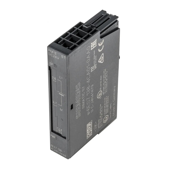
Power module PM-E DC24V (6ES7138-
4CA01-0AA0)
SIMATIC
ET 200S distributed I/O
Power module PM-E DC24V
(6ES7138-4CA01-0AA0)
Manual
04/2007
A5E01119952-02
___________________
Preface
___________________
Properties
___________________
Parameters
___________________
Diagnostics
___________________
Configuring
1
2
3
4
Advertisement
Table of Contents


Need help?
Do you have a question about the SIMATIC PM-E and is the answer not in the manual?
Questions and answers