Table of Contents
Advertisement
Advertisement
Table of Contents

Related Manuals for Siemens Simantic ET200SP


Summary of Contents for Siemens Simantic ET200SP
- Page 2 ___________________ Preface ___________________ Guide to documentation ___________________ System overview ___________________ SIMATIC Application planning ___________________ Installation ET 200SP ___________________ Distributed I/O system Wiring ___________________ Configuring ___________________ Basics of program execution System Manual ___________________ Protection ___________________ Configuration control (option handling) ___________________ Commissioning ___________________ SIMATIC memory card ___________________...
- Page 3 Note the following: WARNING Siemens products may only be used for the applications described in the catalog and in the relevant technical documentation. If products and components from other manufacturers are used, these must be recommended or approved by Siemens. Proper transport, storage, installation, assembly, commissioning, operation and maintenance are required to ensure that the products operate safely and without any problems.
-
Page 4: Preface
Preface Preface Purpose of the documentation This documentation provides important information on configuring, installing, wiring and commissioning the ET 200SP distributed I/O system. Basic knowledge required A basic knowledge of automation technology is required to understand the documentation. Validity of the documentation This documentation applies to the distributed I/O system, ET 200SP. - Page 5 Proper use of hardware products This equipment is only allowed to be used for the applications described in the catalog and in the technical description, and only in conjunction with non-Siemens equipment and components recommended by Siemens. Correct transport, storage, installation and assembly, as well as careful operation and maintenance, are required to ensure that the product operates safely and without faults.
- Page 6 In order to protect plants, systems, machines and networks against cyber threats, it is necessary to implement – and continuously maintain – a holistic, state-of-the-art industrial security concept. Siemens’ products and solutions only form one element of such a concept. Customer is responsible to prevent unauthorized access to its plants, systems, machines and networks.
- Page 7 This information is provided by the Siemens Industry Online Support in the Internet (http://www.siemens.com/automation/service&support). Industry Mall The Industry Mall is the catalog and order system of Siemens AG for automation and drive solutions on the basis of Totally Integrated Automation (TIA) and Totally Integrated Power (TIP).
-
Page 8: Table Of Contents
Table of contents Preface ..............................4 Guide to documentation ........................13 System overview ........................... 17 What is the SIMATIC ET 200SP distributed I/O system? ............17 What are fail-safe automation systems and fail-safe modules? ..........20 How are SIMATIC Safety F-systems structured with ET 200SP? ......... 21 Components ........................... - Page 9 Table of contents Wiring ..............................75 Rules and regulations for operation ..................75 Additional rules and regulations for the operation of the ET 200SP with fail-safe modules ..........................77 5.2.1 Safety extra low voltage for fail-safe modules and fail-safe motor starters ......77 5.2.2 Requirements for sensors and actuators for fail-safe modules and fail-safe motor starters ............................
- Page 10 Table of contents Configuring ............................140 Configuring ET 200SP ......................140 Configuring the CPU ......................143 6.2.1 Reading out the configuration ....................143 6.2.2 Addressing ........................... 145 6.2.3 Process images and process image partitions ..............147 6.2.3.1 Process image - overview ....................147 6.2.3.2 Automatically updating process image partitions ..............
- Page 11 Table of contents Commissioning ........................... 197 10.1 Overview ..........................197 10.2 Commissioning the ET 200SP for PROFINET IO ..............199 10.2.1 ET 200SP CPU as an IO controller ..................199 10.2.2 ET 200SP CPU as an I-device ..................... 201 10.2.3 ET 200SP as an IO device ....................
- Page 12 Table of contents Maintenance ............................236 12.1 Removing and inserting I/O modules/motor starters ............236 12.2 Changing the type of an I/O module ..................239 12.3 Replacing an I/O module ..................... 241 12.4 Replacing a motor starter ..................... 242 12.5 Replacing the terminal box on the BaseUnit ................
-
Page 13: Guide To Documentation
Guide to documentation The documentation for the SIMATIC ET 200SP distributed I/O system is arranged into three areas. This arrangement enables you to access the specific content you require. Basic information The system manual describes in detail the configuration, installation, wiring and commissioning of the SIMATIC ET 200SP. - Page 14 You need to register once to use the full functionality of "mySupport". You can find "mySupport" in the Internet (https://support.industry.siemens.com/My/ww/en). "mySupport" - Documentation In the Documentation area of "mySupport", you have the possibility to combine complete manuals or parts of them to make your own manual.
- Page 15 ● Manuals, characteristics, operating manuals, certificates ● Product master data You can find "mySupport" - CAx Data in the Internet (http://support.industry.siemens.com/my/ww/en/CAxOnline). Application examples The application examples support you with various tools and examples for solving your automation tasks. Solutions are shown in interplay with multiple components in the system - separated from the focus in individual products.
- Page 16 You can find the SIMATIC Automation Tool on the Internet (https://support.industry.siemens.com/cs/ww/en/view/98161300). PRONETA With SIEMENS PRONETA (PROFINET network analysis), you analyze the plant network during commissioning. PRONETA features two core functions: ● The topology overview independently scans PROFINET and all connected components.
-
Page 17: System Overview
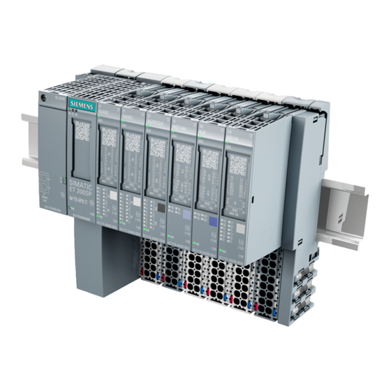
System overview What is the SIMATIC ET 200SP distributed I/O system? SIMATIC ET 200SP SIMATIC ET 200SP is a scalable and highly flexible distributed I/O system for connecting process signals to a higher-level controller via a fieldbus. Customer benefits of the system Figure 2-1 SIMATIC ET 200SP distributed I/O system - Customer benefits Distributed I/O system... - Page 18 System overview 2.1 What is the SIMATIC ET 200SP distributed I/O system? Area of application Thanks to its multifunctionality, the SIMATIC ET 200SP distributed I/O system is suitable for a wide range of applications. Its scalable design allows you to tailor your configuration to local requirements.
- Page 19 System overview 2.1 What is the SIMATIC ET 200SP distributed I/O system? Configuration example ① CPU/interface module ② Light-colored BaseUnit BU..D with infeed of supply voltage ③ Dark-colored BaseUnits BU..B for extending the potential group ④ BaseUnit for motor starter ⑤...
-
Page 20: What Are Fail-Safe Automation Systems And Fail-Safe Modules
Safety Integrated Safety Integrated is the integrated safety concept for automation and drive technology from Siemens. Proven technologies and systems from automation technology are used for safety systems. Safety Integrated includes the complete safety sequence, ranging from sensor, actuator and fail-safe modules right through to the controller, including safety-related communication via standard fieldbuses. -
Page 21: How Are Simatic Safety F-Systems Structured With Et 200Sp
System overview 2.3 How are SIMATIC Safety F-systems structured with ET 200SP? How are SIMATIC Safety F-systems structured with ET 200SP? SIMATIC Safety F-system with ET 200SP The figure below shows an example of a configuration for a SIMATIC Safety F-system with ET 200SP distributed I/O system and PROFINET IO. - Page 22 System overview 2.3 How are SIMATIC Safety F-systems structured with ET 200SP? Example of a configuration with fail-safe I/O modules ① Interface module ② Light-colored BaseUnitBU..D with infeed of supply voltage ③ Dark-colored BaseUnitsBU..B for conducting the potential group further ④...
- Page 23 System overview 2.3 How are SIMATIC Safety F-systems structured with ET 200SP? Hardware and software requirements ET 200SP fail-safe modules are supported by interface modules IM155-6PN BA, firmware V3.2 or higher, IM155-6PN ST, firmware V1.1.1 or higher, IM155-6PN HF, firmware V2.0 or higher, IM155-6PN HS firmware V4.0 or higher and IM155-6DP HF, firmware V1.0 or higher.
- Page 24 System overview 2.3 How are SIMATIC Safety F-systems structured with ET 200SP? Achievable safety classes The fail-safe modules are equipped with integrated safety functions for safety mode. You can achieve the safety classes of the table below: ● With the appropriate parameter assignment of the safety functions in STEP 7 ●...
-
Page 25: Components
System overview 2.4 Components Components Basic components of the ET 200SP distributed I/O system Table 2- 2 Basic components of the ET 200SP Basic component Function Figure Mounting rail in accord- The mounting rail is the rack of the ET 200SP. ance with EN 60715 The ET 200SP is installed on the mounting rail. - Page 26 System overview 2.4 Components Basic component Function Figure Communication module The communication module CM DP CM DP Connects the CPU with PROFIBUS DP • The bus connection is an RS485 interface • Interface module for The interface module: PROFINET IO Can be used as IO device on •...
- Page 27 System overview 2.4 Components Basic component Function Figure BusAdapter The BusAdapters allow free selection of the connection technology for PROFINET IO. The following versions are available for PROFINET CPU/interface modules: For standard RJ45 connector (BA 2×RJ45) • ① For direct connection of the bus cable •...
- Page 28 System overview 2.4 Components Basic component Function Figure BaseUnit The BaseUnits provide the electrical and me- chanical connection of the ET 200SP mod- ules. Place the I/O modules or the motor starter onto the BaseUnits. Suitable BaseUnits are available for each of the different requirements (see Selecting the BaseUnit for I/O modules (Page 36)).
- Page 29 System overview 2.4 Components Basic component Function Figure Motor starter/fail-safe The motor starter is a switching and protection motor starter device for 1-phase and 3-phase loads. The motor starter is available as a direct-on- line and reversing starter. BU cover Insert the BU cover on the BaseUnits: Whose slots are not occupied by I/O mod- •...
- Page 30 System overview 2.4 Components Basic component Function Figure Coding element The coding element codes the I/O module with the BaseUnit. There are two versions: ① Mechanical coding element : Ensures • the coding ② Electronic coding element : This version •...
- Page 31 The functions of the 3DI/LC module are not relevant to functional safety. Detailed information on the functions when using a 3DI/LC module can be found in the Manual (https://support.industry.siemens.com/cs/ww/e n/view/109479973). Mechanical bracket for Use the mechanical bracket for additional BaseUnit fixing of the motor starter.
-
Page 32: Application Planning
You will find a complete overview of the possibilities of combining BaseUnits and I/O modules /motor starters in the Product information for documentation of the ET 200SP I/O system (http://support.automation.siemens.com/WW/view/en/73021864). Table 3- 1 Selecting a suitable BaseUnit for I/O modules... - Page 33 Application planning Selecting a BaseUnit I/O module Examples of suitable I/O modules for BU types (example) I/O module (example) BaseUnit BU type B0 Digital output module RQ 4×120VDC- BU20-P12+A4+0B with relay 230VAC/5A NO ST (BU..B, dark-colored (6ES7193-6BP20-0BB0) BaseUnit) (6ES7132-6HD00-0BB0) 6ES7...B0 •...
- Page 34 Application planning Table 3- 2 BaseUnit for motor starters Selecting the BaseUnit BU-30- BU-30- BU-30- BU-30- BU-30- BU-30- 24 V infeed 500 V infeed F-DI terminals Motor starters DS 0.3 - 1A 3RK1308- 0AB00-0CP0 DS 0.9 - 3A 3RK1308- 0AC00-0CP0 DS 2.8 - 9A 3RK1308- 0AD00-0CP0...
- Page 35 Additional information on the functional assignment of the terminals and on the associated BaseUnits can be found in one of the following manuals: ● Manual for the relevant I/O module (http://support.automation.siemens.com/WW/view/en/55679691/133300) ● Manual BaseUnits (http://support.automation.siemens.com/WW/view/en/59753521) ● Motor starter (https://support.industry.siemens.com/cs/ww/en/view/109479973) manual Distributed I/O system System Manual, 12/2016, A5E03576849-AG...
-
Page 36: Selecting The Baseunit For I/O Modules
Application planning 3.1 Selecting the BaseUnit for I/O modules Selecting the BaseUnit for I/O modules 3.1.1 Digital, fail-safe, communication, technology or analog modules without temperature measurement Selection of a suitable BaseUnit ① Light-colored BaseUnit: Configuration of a new potential group, electrical isolation from adjacent module on the left. The first BaseUnit of the ET 200SP is usually a light-colored BaseUnit for feeding the supply voltage L+. -
Page 37: Analog Modules With Temperature Measurement
Application planning 3.1 Selecting the BaseUnit for I/O modules 3.1.2 Analog modules with temperature measurement Selection of a suitable BaseUnit ① Light-colored BaseUnit: Configuration of a new potential group, electrical isolation from adja- cent module on the left. The first BaseUnit of the ET 200SP is usually a light -colored BaseUnit for feeding the supply voltage L+. -
Page 38: Selecting Motor Starters With A Suitable Baseunit
Application planning 3.2 Selecting motor starters with a suitable BaseUnit Selecting motor starters with a suitable BaseUnit 3.2.1 Selecting a BaseUnit for motor starters The motor starter BaseUnits "BU30-MS1", "BU30-MS2", "BU30-MS3" and "BU30-MS4" are compatible with all non-fail-safe motor starters. The motor starter BaseUnits "BU30-MS1", "BU30-MS2", "BU30-MS3", "BU30-MS4", "BU30-MS5"... -
Page 39: Selecting The Motor Starter
Application planning 3.2 Selecting motor starters with a suitable BaseUnit 3.2.2 Selecting the motor starter You select the suitable motor starter using the load type according to the following scheme: Distributed I/O system System Manual, 12/2016, A5E03576849-AG... -
Page 40: Selecting Accessories For Motor Starters
Application planning 3.2 Selecting motor starters with a suitable BaseUnit 3.2.3 Selecting accessories for motor starters Observe the installation conditions of the station with ET 200SP motor starters. The figure below shows the criteria the station must meet: Distributed I/O system System Manual, 12/2016, A5E03576849-AG... -
Page 41: Hardware Configuration
Properties Rule Number of modules Maximum of 12/30/32/64 I/O modules (depending on the CPU used/the interface module used; see CPU (http://support.automation.siemens.com/WW/view/en/9046643 9/133300) and interface module (http://support.automation.siemens.com/WW/view/en/5568331 6/133300) manuals) For every 6 F-modules F-RQ 1x24VDC/24..230VAC/5A (6ES7136-6RA00-0BF0), the maximum configuration is re- duced by 1 module. - Page 42 * 1.125) infeed bus n = number of motor starters of a potential group on the infeed bus Refer to the Manual (https://support.industry.siemens.com/cs/ww/en/view/109479973) for details of how to assign the basic rated operational current I parameter. The following values apply for the potential group of the AC infeed: ●...
-
Page 43: Forming Potential Groups
Application planning 3.4 Forming potential groups Forming potential groups 3.4.1 Basics Introduction Potential groups for the ET 200SP distributed I/O system are formed by systematically arranging the BaseUnits. Requirements For formation of potential groups, the ET 200SP distinguishes between the following BaseUnits: ●... - Page 44 Application planning 3.4 Forming potential groups Placement and grouping of I/O modules Each BaseUnit BU...D that you install in the ET 200SP configuration opens a new potential group and supplies all subsequent I/O modules (on BaseUnits BU...B) with the necessary supply voltage.
- Page 45 ● Maximum current carrying capacity (at 60 °C ambient air temperature): 10 A ● Permissible voltage: Depending on the BaseUnit type (see BaseUnit manual (http://support.automation.siemens.com/WW/view/en/59753521)) Self-assembling voltage buses You must feed in the supply voltage L+ via the BaseUnit BU...D, BU30-MS1 or BU30-MS3 .
- Page 46 Application planning 3.4 Forming potential groups Operating principle CPU/interface module Server module BaseUnit BU...D Self-assembling voltage buses P1/P2 BaseUnit BU...B AUX bus Potential group 1 Infeed bus 500 V AC (L1, L2(N), L3, PE) Potential group 2 Supply voltage L+ Potential group 3 Supply voltage L+ (3) BaseUnit BU...B with dummy module...
-
Page 47: Forming Potential Groups With Ac I/O Modules
Application planning 3.4 Forming potential groups 3.4.2 Forming potential groups with AC I/O modules Introduction The AC I/O modules of the ET 200SP are required to connect sensors/actuators with alternating voltage 24 to 230 V AC. Requirements BaseUnits BU20-P12+A0+4B (BU type B1) and ●... - Page 48 Application planning 3.4 Forming potential groups Operating principle Connect the required alternating voltage for the AC I/O modules directly at the BaseUnits BU20-P12+A0+4B (terminals 1L, 2L/1N, 2N). Insert the AC I/O modules on the BaseUnits. Note Placing the BaseUnits for AC I/O modules If you insert an AC I/O module as the first I/O module, a BaseUnit BU20-P12+A0+4B can be the first BaseUnit to the right of the CPU/interface module in the ET 200SP configuration.
-
Page 49: Forming Potential Groups With Fail-Safe Modules
Application planning 3.4 Forming potential groups 3.4.3 Forming potential groups with fail-safe modules Introduction ET 200SP distributed I/O systems can be configured using fail-safe and non-fail-safe modules. This chapter provides an example of a mixed configuration comprising fail-safe and non-fail-safe modules. Example of an ET 200SP configuration with fail-safe and non-fail-safe modules In principle, it is not necessary to operate fail-safe and non-fail-safe modules in separate potential groups. -
Page 50: Forming Potential Groups With Motor Starters
Application planning 3.4 Forming potential groups 3.4.4 Forming potential groups with motor starters Properties of the 500 V AC infeed bus The infeed bus has the following properties: ● The infeed bus is assembled by lining up the motor starter BaseUnits "BU30-MSx". ●... - Page 51 Application planning 3.4 Forming potential groups Requirements Use the following devices to form potential groups with motor starters: ● BaseUnits BU30-MSx ● 3RK1308-0xx00-0CP0 motor starters Operating principle Feed in the supply voltage L+ via the BaseUnit BU30-MS1 and BU30-MS3 at the 24V DC and M terminals.
-
Page 52: Configuration Examples For Potential Groups
Application planning 3.5 Configuration examples for potential groups Configuration examples for potential groups Configuration examples with BaseUnits Table 3- 4 Configuration examples with BaseUnits BaseUnits Configuration BU15- P16+A0+2D BU15- P16+A0+2B BU15- P16+A0+2D BU15- P16+A0+2B BU20- P12+A0+0B Distributed I/O system System Manual, 12/2016, A5E03576849-AG... - Page 53 Application planning 3.5 Configuration examples for potential groups BaseUnits Configuration BU15- P16+A10+2D BU15- P16+A10+2B Distributed I/O system System Manual, 12/2016, A5E03576849-AG...
-
Page 54: Installation
Installation Basics Introduction All modules of the ET 200SP distributed I/O system are open equipment. This means you may only set up the distributed I/O system ET 200SP in enclosures, cabinets or electrical equipment rooms and in a dry environment (IP20 degree of protection). These enclosures, cabinets or electrical equipment rooms must only be accessible with a key or tool. - Page 55 Installation 4.1 Basics Mounting rail Mount the ET 200SP distributed I/O system on a mounting rail in accordance with EN 60715 (35 × 7.5 mm or 35 × 15 mm). You need to ground the mounting rail separately in the control cabinet. Exception: If you install the rail on grounded, zinc-plated mounting plates, there is no need to ground the rail separately.
- Page 56 Installation 4.1 Basics Minimum clearances The figure below shows the minimum clearances you must observe when installing or dismantling the ET 200SP distributed I/O system. Figure 4-1 Minimum clearances Distributed I/O system System Manual, 12/2016, A5E03576849-AG...
- Page 57 Installation 4.1 Basics General rules for installation WARNING Hazardous Voltage Can Cause Death, Serious Injury, or Property Damage. Hazardous electrical voltage can cause electric shock, burns and property damage. Disconnect your system and devices from the power supply before starting any assembly tasks.
-
Page 58: Installation Conditions For Motor Starters
Installation 4.2 Installation conditions for motor starters Installation conditions for motor starters Observe the following installation conditions when using an ET 200SP motor starter: ● Mounting position You can install the motor starter vertically, horizontally or on its back. The mounting position refers to the alignment of the mounting rail The maximum permissible ambient temperature range depends on the mounting position: –... - Page 59 Installation 4.2 Installation conditions for motor starters Mount the dummy module The figure below provides a schematic representation of how to implement measures for improving interference immunity. ① ⑥ Interface module Motor starter ② ⑦ Digital input module Motor starter ③...
-
Page 60: Mounting The Cpu/Interface Module
Required tools 3 to 3.5 mm screwdriver (only for mounting and removing the BusAdapter) Mounting the CPU/interface module Watch the video sequence (http://support.automation.siemens.com/WW/view/en/95886218) To install a CPU/interface module, follow these steps: 1. Install the CPU/interface module on the mounting rail. - Page 61 Installation 4.3 Mounting the CPU/interface module Dismantling the CPU/interface module The CPU/interface module is wired and BaseUnits are located to its right. To remove the CPU/interface module, follow these steps: 1. Switch off the supply voltage on the CPU/interface module. Remove the 24 V DC connector from the CPU/interface module.
-
Page 62: Installing The Cm Dp Communication Module
Installation 4.4 Installing the CM DP communication module Installing the CM DP communication module Introduction You need the CM DP communication module to use the CPU with a DP master or DP slave. Requirements ● The mounting rail is fitted. ●... - Page 63 Installation 4.4 Installing the CM DP communication module Removing a CM DP The CPU and the CM DP are wired and BaseUnits are located to its right. To remove the CM DP communication module, follow these steps: 1. Switch off the supply voltage on the CPU. 2.
-
Page 64: Mounting Baseunits For I/O Modules
3 to 3.5 mm screwdriver (only for dismantling the terminal box and the encoding element) Installing a BaseUnit Watch "Install configuration" video sequence (http://support.automation.siemens.com/WW/view/en/95886218) To install a BaseUnit, follow these steps: 1. Install the BaseUnit on the mounting rail. 2. Swivel the BaseUnit backwards until you hear it click into the mounting rail. - Page 65 Installation 4.5 Mounting BaseUnits for I/O modules Removing a BaseUnit WARNING Hazardous Voltage Hazardous electrical voltage can cause electric shock, burns and property damage. Disconnect your system and devices from the power supply before starting any assembly tasks. To remove a BaseUnit, follow these steps: The BaseUnit is wired and there are other BaseUnits to its right and left.
-
Page 66: Mounting And Dismantling Baseunits For Motor Starters
Installation 4.6 Mounting and dismantling BaseUnits for motor starters Mounting and dismantling BaseUnits for motor starters Requirements ● The mounting rail is fitted. ● When using a 15 mm mounting rail, the mechanical bracket (3RK1908-1EA00-1BP0) must be mounted. Note Mechanical bracket for BaseUnit You will find out how to mount the mechanical bracket for the BaseUnit in chapter "Mounting the mechanical bracket for the BaseUnit (Page 71)". - Page 67 Installation 4.6 Mounting and dismantling BaseUnits for motor starters Disassembling the BaseUnit WARNING Hazardous Voltage Hazardous electrical voltage can cause electric shock, burns and property damage. Disconnect your system and devices from the power supply before starting any assembly tasks. To disassemble the BaseUnit, proceed as follows: 1.
-
Page 68: Installing The Server Module
The last BaseUnit is mounted. Installing the server module Watch "Install configuration" video sequence (http://support.automation.siemens.com/WW/view/en/95886218) Proceed as follows to install a server module: 1. Install the server module on the mounting rail on the right next to the last BaseUnit. -
Page 69: Mounting Further Accessories For Motor Starters
Installation 4.8 Mounting further accessories for motor starters Mounting further accessories for motor starters 4.8.1 Mounting the cover for the 500 V AC infeed bus Introduction The 500 V infeed bus connects all SIMATIC ET 200SP motor starters. For finger-safe termination of the infeed bus, you must use the cover. - Page 70 Installation 4.8 Mounting further accessories for motor starters Procedure Proceed as follows to mount the infeed bus cover on a SIMATIC ET 200SP motor starter: 1. Press the cover onto the opening of the BaseUnit on the right until it audibly engages. The cover can be removed again using 2 fingers and without tools.
-
Page 71: Mounting The Mechanical Bracket For The Baseunit
Installation 4.8 Mounting further accessories for motor starters 4.8.2 Mounting the mechanical bracket for the BaseUnit Introduction To achieve higher stability, you can use a mechanical bracket on 7.5 mm and 15 mm mounting rails. You must use the mechanical bracket in the following situations: ●... - Page 72 Installation 4.8 Mounting further accessories for motor starters Procedure To mount the mechanical bracket, proceed as follows: 1. Insert the mechanical bracket into the opening at the bottom of the BaseUnit. You use the same mechanical bracket for both mounting rails, rotated through 180° respectively.
- Page 73 Installation 4.8 Mounting further accessories for motor starters The figures below show the mechanical bracket after installation on a 7.5 mm or 15 mm mounting rail. Distributed I/O system System Manual, 12/2016, A5E03576849-AG...
-
Page 74: Mounting The Bu Cover
Installation 4.8 Mounting further accessories for motor starters 4.8.3 Mounting the BU cover Introduction BU covers are plugged onto BaseUnits whose slots have been reserved for future expansion (as empty slots). The BU covers for motor starters serve as touch protection covers for unoccupied slots. -
Page 75: Wiring
Wiring Rules and regulations for operation Introduction When installing the ET 200SP distributed I/O system as part of a plant or system, special rules and regulations need to be adhered to depending on the area of application. This section provides an overview of the most important rules that must be observed for the integration of the ET 200SP distributed I/O system in a plant or system. - Page 76 ● For signal and bus lines, you must ensure that a wire/cable break or a cross-circuit does not lead to undefined states of the plant or system. Reference You can find more information in the Designing interference-free controllers (http://support.automation.siemens.com/WW/view/en/59193566) function manual. Distributed I/O system System Manual, 12/2016, A5E03576849-AG...
-
Page 77: Additional Rules And Regulations For The Operation Of The Et 200Sp With Fail-Safe Modules
Wiring 5.2 Additional rules and regulations for the operation of the ET 200SP with fail-safe modules Additional rules and regulations for the operation of the ET 200SP with fail-safe modules 5.2.1 Safety extra low voltage for fail-safe modules and fail-safe motor starters WARNING The fail-safe modules must be operated with safety extra low voltage (SELV, PELV). -
Page 78: Requirements For Sensors And Actuators For Fail-Safe Modules And Fail-Safe Motor Starters
(230 V AC → 24 V DC) with a mains buffering time of at least 20 ms. The latest up-to-date information on PS components is available on the Internet (https://mall.industry.siemens.com). These requirements, of course, also apply to power packs/power supply units not constructed using ET 200SP / S7-300-/400-/1500 technology. - Page 79 Wiring 5.2 Additional rules and regulations for the operation of the ET 200SP with fail-safe modules Additional sensor requirements General rule: To achieve SIL3/Cat. 3/PLe, a single-channel sensor is adequate. However, to achieve SIL3/Cat. 3/PLe with a single-channel sensor, the sensor itself must be SIL3/Cat.
- Page 80 Wiring 5.2 Additional rules and regulations for the operation of the ET 200SP with fail-safe modules Additional requirements for actuators The fail-safe output modules test the outputs at regular intervals. The F-module briefly switches off the activated outputs and, if necessary, switches on the deactivated outputs. You can assign the maximum duration of the test pulses (dark and light period) with parameters.
-
Page 81: Crosstalk Of Digital Input/Output Signals
Wiring 5.3 Additional rules and instructions for operation with motor starters 5.2.3 Crosstalk of digital input/output signals When fail-safe digital output and input signals are in a single cable, F-DQ modules and F- PM-E modules may experience readback errors. Cause: capacitive crosstalk During the bit pattern test of the outputs or the sensor supply of the inputs, the steep switching edge of the output drivers caused by the coupling capacitance of the line may result in crosstalk to other non-activated output or input channels. -
Page 82: Operating The Et 200Sp On Grounded Incoming Supply
Wiring 5.4 Operating the ET 200SP on grounded incoming supply Operating the ET 200SP on grounded incoming supply Introduction Below you will find information on the overall configuration of an ET 200SP distributed I/O system on a grounded incoming supply (e.g. TN-S network). The specific subjects discussed are: ●... - Page 83 Wiring 5.4 Operating the ET 200SP on grounded incoming supply Short-circuit / overload protection Various measures as protection against short-circuits and overloads are required for setting up a full installation. The type of components and the binding protective measures depend on which IEC (DIN VDE) regulation applies to your system configuration.
- Page 84 Wiring 5.4 Operating the ET 200SP on grounded incoming supply ET 200SP in the overall configuration The figure below shows the overall configuration of the ET 200SP distributed I/O system (load current supply and grounding concept) with supply from a TN-S network. ①...
-
Page 85: Electrical Configuration Of The Et 200Sp
Wiring 5.5 Electrical configuration of the ET 200SP Electrical configuration of the ET 200SP Electrical isolation Electrical relationships With the ET 200SP distributed I/O system, there is electrical isolation between: ● The load circuits/process and all other circuit components of the ET 200SP distributed I/O system. - Page 86 Wiring 5.5 Electrical configuration of the ET 200SP Figure 5-3 Electrical relationships for ET 200SP with interface module (using IM 155-6 PN ST as an example) Distributed I/O system System Manual, 12/2016, A5E03576849-AG...
-
Page 87: Wiring Rules
Wiring 5.6 Wiring rules Wiring rules Wiring rules for the CPU/interface module and BaseUnits for I/O modules Wiring rules for ... CPU/interface module (supply BaseUnits voltage) (push-in terminal) Connectable cross-sections for solid cables 0.2 to 2.5 mm : 24 to 13 Connectable cross- Without end sleeve 0.2 to 2.5 mm... - Page 88 Wiring 5.6 Wiring rules TWIN end sleeves for the cables of the I/O modules' push-in terminals Due to the space required by TWIN end sleeves with 0.75 mm cross-section, you must ensure a correct angle for the cable arrangement when crimping the TWIN end sleeve so that the cables are optimally arranged.
- Page 89 Wiring 5.6 Wiring rules Safety standards for fail-safe motor starters Fail-safe motor starters fulfill the following standards under certain conditions: ● PL e/Cat. 4 according to EN ISO 13849-1 ● Safety Integrity Level SILCL3 acc. to IEC 62061 To fulfill both standards, lay cross-circuit proof and P-cross-circuit proof control cables from the safe output of a sensor or F-DQ to the safe input of the motor starter, e.g.
-
Page 90: Wiring Baseunits For I/O Modules
Wiring 5.7 Wiring BaseUnits for I/O modules Wiring BaseUnits for I/O modules Introduction The BaseUnits connect the ET 200SP distributed I/O system to the process. The following versions of the BaseUnits can be used: ● BaseUnits (with light-colored terminal box) for opening a potential group: BU..D ●... - Page 91 Tool-free connection of cables: single-wire without wire end ferrule, multi-wire (stranded) with wire end ferrule or ultrasonically sealed Watch the video sequence (http://support.automation.siemens.com/WW/view/en/95886218) To connect a wire without tools, follow these steps: 1. Strip 8 to 10 mm of the wires.
-
Page 92: Connecting Cable Shields For I/O Modules
Wiring 5.8 Connecting cable shields for I/O modules Connecting cable shields for I/O modules Introduction ● You need the shield connector to contact cable shields (e.g. for analog modules). The shield connector conducts interference currents on cable shields to ground via the mounting rail. - Page 93 5.8 Connecting cable shields for I/O modules Procedure Watch the "Wiring BaseUnits" video sequence (http://support.automation.siemens.com/WW/view/en/95886218) To connect the cable shield, follow these steps: 1. If necessary, connect the supply voltage L+ and ground to the BaseUnit. 2. Press the shield contact up into the mount until you hear it click into place.
-
Page 94: Wiring Baseunits For Motor Starters
Wiring 5.9 Wiring BaseUnits for motor starters Wiring BaseUnits for motor starters Introduction The following versions of BaseUnits can be used: ● BU30-MS1 (with 500 V and 24 V infeed) ● BU30-MS2 (with 500 V infeed and 24 V forwarding) ●... - Page 95 Wiring 5.9 Wiring BaseUnits for motor starters The following figure shows an example of a BaseUnit BU30-MS5 (with the maximum number of terminals): ① Push-in terminal ② Spring release Figure 5-9 Terminals on a BaseUnit BU30-MS5 DANGER Hazardous Voltage Can Cause Death, Serious Injury, or Property Damage. Hazardous electrical voltage can cause electric shock, burns and property damage.
- Page 96 5. Check whether or not the conductor is firmly connected by pulling on the cable. Video sequence At the following Internet link, you can see a video about connecting conductors: Wire BaseUnits (http://support.automation.siemens.com/WW/view/en/95886218) Releasing conductors To release a conductor, proceed as follows: 1.
-
Page 97: Connecting The 3Di/Lc Module For The Motor Starter
5.10 Connecting the 3DI/LC module for the motor starter 5.10 Connecting the 3DI/LC module for the motor starter You will find further information on the 3DI/LC module in the ET 200SP motor starter (https://support.industry.siemens.com/cs/ww/en/view/109479973) manual. Procedure The figure below shows the connections of the 3DI/LC module. ①... - Page 98 Wiring 5.10 Connecting the 3DI/LC module for the motor starter Terminal sketch of the 3DI/LC module The following diagram shows a terminal sketch of the 3DI/LC module: Figure 5-10 Connection example of inputs Distributed I/O system System Manual, 12/2016, A5E03576849-AG...
-
Page 99: Connecting The Supply Voltage To The Cpu/Interface Module
Wiring 5.11 Connecting the supply voltage to the CPU/interface module 5.11 Connecting the supply voltage to the CPU/interface module Introduction The supply voltage of the CPU/interface module is supplied by means of a 4-pin connector plug located on the front of the CPU/interface module. Power supply unit Only use power supply units of type SELV/PELV with safe electrically isolated functional extra low voltage (≤... - Page 100 Tool-free connection of cables: single-wire without end sleeve, multi-wire (stranded) with end sleeve or ultrasonically sealed Watch video sequence: "Connect BusAdapter to the interface module" (http://support.automation.siemens.com/WW/view/en/95886218) To connect a wire without tools, follow these steps: 1. Strip 8 to 10 mm of the wires.
-
Page 101: Connecting Interfaces For Communication
Wiring 5.12 Connecting interfaces for communication 5.12 Connecting interfaces for communication Connect the communication interfaces of the ET 200SP distributed I/O system using the standardized connector or directly. If you want to prepare communication cables yourself, the interface assignment is specified in the manuals of the corresponding modules. Observe the mounting instructions for the connectors. - Page 102 5.12 Connecting interfaces for communication Procedure Watch video sequence: "Connect BusAdapter BA 2xRJ45 to the interface module" (http://support.automation.siemens.com/WW/view/en/95886218) To connect PROFINET IO to the CPU/interface module via the BA 2xRJ45 BusAdapter, follow these steps: 1. Plug the BusAdapter BA 2×RJ45 into the CPU/interface module.
- Page 103 Wiring 5.12 Connecting interfaces for communication BA 2×RJ45 BusAdapter mounted ① ② BA 2×RJ45 BusAdapter ③ PROFINET connecting cable ④ Interface module Figure 5-13 Connecting the BA 2×RJ45 BusAdapter to the CPU/interface module Note Installation guidelines for modules with PROFINET IO interfaces Only when all connected nodes are equipped with a SELV/PELV power supply (or have equivalent protection), is it permitted to operate the modules with PROFINET IO interfaces in LANs (Local Area Networks).
-
Page 104: Connecting Profinet Io To The Cpu/Interface Module Via The Ba 2Xfc Busadapter
Wiring 5.12 Connecting interfaces for communication 5.12.2 Connecting PROFINET IO to the CPU/interface module via the BA 2xFC BusAdapter Introduction You connect PROFINET IO to the CPU/interface module via the BusAdapter BA 2×FC. To do this, screw the BusAdapter BA 2xFC to the connected PROFINET connecting cable on the CPU/interface module. - Page 105 5.12 Connecting interfaces for communication Procedure Watch video sequence: "Connect BusAdapter BA 2xFC to the interface module" (http://support.automation.siemens.com/WW/view/en/95886218) To connect PROFINET IO to the CPU/interface module via the BA 2xFC BusAdapter, follow these steps: 1. Strip the sleeve of the PROFINET connecting cable as follows:...
- Page 106 Wiring 5.12 Connecting interfaces for communication 5. Close the cover of the connection element and push the locking slide forwards as far as it will go. 6. Connect and screw the BA 2×FC BusAdapter to the CPU/interface module (1 screw with 0.2 Nm tightening torque).
- Page 107 Wiring 5.12 Connecting interfaces for communication BA 2×FC BusAdapter mounted ① ② BA 2×FC BusAdapter ③ PROFINET connecting cable ④ Connection element ⑤ Interface module Figure 5-17 Connecting the BA 2×FC BusAdapter to the CPU/interface module Note Installation guidelines for modules with PROFINET IO interfaces Only when all connected nodes are equipped with a SELV/PELV power supply (or have equivalent protection) is it permitted to operate the modules with PROFINET IO interfaces in LANs (Local Area Networks).
-
Page 108: Connecting Profinet Io To The Cpu/Interface Module Via Ba 2Xscrj Busadapter
Wiring 5.12 Connecting interfaces for communication 5.12.3 Connecting PROFINET IO to the CPU/interface module via BA 2xSCRJ BusAdapter Introduction You can connect PROFINET IO to the CPU/interface module optically with fiber-optic cables using an SC RJ connector via the BA 2×SCRJ BusAdapter. To do this, screw the BA 2×SCRJ BusAdapter onto the CPU/interface module and insert the SC RJ connector. - Page 109 Wiring 5.12 Connecting interfaces for communication Requirements ● Prepare the IE POF cables with the connectors IE SC RJ POF Plug or IE SC RJ PCF Plug. For detailed information, refer to the assembly instructions POF Fiber-optic Cables with IE Termination Kit SC RJ POF Plug (A5E00351141) or PCF Fiber-optic Cables with the IE Termination Kit SC RJ PCF Plug (A5E00835119).
- Page 110 This will prevent any attenuation losses caused by re-bent, heavily stressed portions of the fiber-optic cores. Reference For more information on the installation guidelines for fiber-optic cables, refer to the SIMATIC NET PROFIBUS Network Manual (http://support.automation.siemens.com/WW/view/en/35222591). Distributed I/O system System Manual, 12/2016, A5E03576849-AG...
-
Page 111: Connecting Profinet Io To The Interface Module Via The Ba Scrj/Rj45 Busadapter
Wiring 5.12 Connecting interfaces for communication 5.12.4 Connecting PROFINET IO to the interface module via the BA SCRJ/RJ45 BusAdapter Introduction You connect PROFINET IO to the interface module via the BA SCRJ/RJ45 BusAdapter: ● Optically coupled to fiber-optic cables (FOC) with an SC RJ connector (port 1) or ●... - Page 112 Wiring 5.12 Connecting interfaces for communication BA SCRJ/RJ45 BusAdapter mounted ① Interface module ② BA SCRJ/RJ45 BusAdapter ③ PROFINET connecting cable Figure 5-21 Connecting the BA SCRJ/RJ45 BusAdapter to the interface module Distributed I/O system System Manual, 12/2016, A5E03576849-AG...
-
Page 113: Connecting Profinet Io To The Interface Module Via The Ba Scrj/Fc Busadapter
Wiring 5.12 Connecting interfaces for communication 5.12.5 Connecting PROFINET IO to the interface module via the BA SCRJ/FC BusAdapter Introduction You connect PROFINET IO to the interface module via the BA SCRJ/FC BusAdapter: ● Optically coupled to fiber-optic cables (FOC) with an SC RJ connector (port 1) or ●... - Page 114 Wiring 5.12 Connecting interfaces for communication BA SCRJ/FC BusAdapter mounted ① Interface module ② BA SCRJ/FC BusAdapter ③ PROFINET connecting cable Figure 5-23 Connecting the BA SCRJ/FC BusAdapter to the interface module Distributed I/O system System Manual, 12/2016, A5E03576849-AG...
-
Page 115: Connecting Profinet Io To The Interface Module Via The Ba 2Xlc Busadapter
Wiring 5.12 Connecting interfaces for communication 5.12.6 Connecting PROFINET IO to the interface module via the BA 2xLC BusAdapter Introduction Via the BA 2xLC BusAdapter, you connect the PROFINET IO to the interface module optically with fiber-optic cables using an LC connector. To do this, screw the BA 2xLC BusAdapter onto the interface module and insert the LC connector. - Page 116 Wiring 5.12 Connecting interfaces for communication Requirements ● Prepare the IE FC FO cable with the IE FC FO LC plug connectors. For detailed instructions, refer to the assembly instructions Preparing IE FC FO Cable with the plug-in connector IE FC FO LC Plug (A5E36312721). ●...
- Page 117 This will prevent any attenuation losses caused by re-bent, heavily stressed portions of the fiber-optic cores. Reference For more information on the installation guidelines for fiber-optic cables, refer to the SIMATIC NET PROFIBUS Network Manual (http://support.automation.siemens.com/WW/view/en/35222591). Distributed I/O system System Manual, 12/2016, A5E03576849-AG...
-
Page 118: Connecting Profinet Io To The Interface Module Via The Ba Lc/Rj45 Busadapter
Wiring 5.12 Connecting interfaces for communication 5.12.7 Connecting PROFINET IO to the interface module via the BA LC/RJ45 BusAdapter Introduction You connect PROFINET IO to the interface module via the BA LC/RJ45 BusAdapter: ● Optically coupled to glass fiber-optic cables with an LC connector (port 1) or ●... - Page 119 Wiring 5.12 Connecting interfaces for communication BA LC/RJ45 BusAdapter mounted ① Interface module ② BA LC/RJ45 BusAdapter ③ PROFINET connecting cable Figure 5-27 Connecting the BA LC/RJ45 BusAdapter to the interface module Distributed I/O system System Manual, 12/2016, A5E03576849-AG...
-
Page 120: Connecting Profinet Io To Interface Module Via Ba Lc/Fc Busadapter
Wiring 5.12 Connecting interfaces for communication 5.12.8 Connecting PROFINET IO to interface module via BA LC/FC BusAdapter Introduction You connect PROFINET IO to the interface module via the BA LC/FC BusAdapter: ● Optically coupled to glass fiber-optic cables with an LC connector (port 1) or ●... -
Page 121: Connecting Profinet Io (Port P3) To The Cpu
Wiring 5.12 Connecting interfaces for communication BA LC/FC BusAdapter mounted ① Interface module ② BA LC/FC BusAdapter ③ PROFINET connecting cable Figure 5-29 Connecting the BA LC/FC BusAdapter to the interface module 5.12.9 Connecting PROFINET IO (port P3) to the CPU Introduction You use the RJ-45 bus connector to connect PROFINET IO (port P3) directly to the CPU. - Page 122 Wiring 5.12 Connecting interfaces for communication Procedure Insert the RJ45 bus connector into the PROFINET port (port P3) on the CPU. Note Cable support and strain relief If you are using a FastConnect RJ-45 bus connector with 90° cable outlet (6GK1901-1BB20- 2AA0), we recommend you provide strain relief for the PROFINET connecting cable.
-
Page 123: Connecting The Profibus Dp Interface To The Interface Module/Communications Module Cm Dp
Wiring 5.12 Connecting interfaces for communication 5.12.10 Connecting the PROFIBUS DP interface to the interface module/communications module CM DP Introduction Using the bus connector (RS485), connect the PROFIBUS DP to the interface module/communications module CM DP. Required tools 3 to 3.5 mm screwdriver Procedure To connect the PROFIBUS DP interface to the interface module / DP communication module CM DP, follow these steps:... -
Page 124: Inserting I/O Modules / Motor Starters And Bu Covers
5.13 Inserting I/O modules / motor starters and BU covers Reference You can find additional information on the PROFIBUS FastConnect bus connector in the corresponding product information on the Internet (http://support.automation.siemens.com/WW/view/en/58648998). 5.13 Inserting I/O modules / motor starters and BU covers Introduction ●... - Page 125 5.13 Inserting I/O modules / motor starters and BU covers Plugging in I/O modules and BU covers Watch video sequence: "Insert I/O modules" (http://support.automation.siemens.com/WW/view/en/95886218) Install the I/O module or BU cover parallel into the BaseUnit until you hear both latches click into place.
-
Page 126: Mounting/Disassembly Of Motor Starters
Wiring 5.14 Mounting/disassembly of motor starters 5.14 Mounting/disassembly of motor starters 5.14.1 Mounting the fan Procedure Proceed as follows to mount a fan on a SIMATIC ET 200SP motor starter: 1. Slide the fan onto the motor starter until you can hear the fan engage. Observe the blowing direction of the fan when mounting. -
Page 127: Mounting/Disassembly Of Motor Starters
Wiring 5.14 Mounting/disassembly of motor starters 5.14.2 Mounting/disassembly of motor starters Procedure CAUTION Protection against electrostatic charge When handling and installing the SIMATIC ET 200SP motor starter, ensure protection against electrostatic charging of the components. Changes to the system configuration and wiring are only permissible after disconnection from the power supply. - Page 128 Wiring 5.14 Mounting/disassembly of motor starters 4. Turn the mechanical rotary interlock clockwise to the operating position (= end position). ① Operating position/READY The motor starter is firmly locked in the BaseUnit, and all electrical contacts are connected. ② Assembly/disassembly position All electrical contacts are open, and you can use the SIMATIC ET 200SP motor starter in the BaseUnit, or you can remove it from the BaseUnit.
- Page 129 Wiring 5.14 Mounting/disassembly of motor starters Note Parking position/OFF This position is only permissible for maintenance purposes and not for continuous operation. In this position, dust protection and mechanical durability are not ensured. If you do not use the motor starter for an extended period, remove it and attach the BU cover (3RK1908-1CA00-0BP0).
-
Page 130: 3Di/Lc Module
Wiring 5.14 Mounting/disassembly of motor starters 5.14.3 3DI/LC module Introduction The optional 3DI/LC module with three inputs and one further LC input can be connected to the motor starter. The status of the inputs of the 3DI/LC module can be seen via the process image input (PII) of the motor starter. - Page 131 Wiring 5.14 Mounting/disassembly of motor starters Assembly WARNING Risk of injury from automatic restart When you mount the the 3DI/LC module, the motor starter can switch on autonomously if an ON command (DI1 to DI3) is active. This can result in property damage or serious injury caused by connected devices that are automatically started up.
- Page 132 Wiring 5.14 Mounting/disassembly of motor starters The figure below shows a motor starter with a mounted 3DI/LC module. Disassembly Proceed as follows to remove a 3DI/LC module from a motor starter: 1. Push the release lever on the rear of the 3DI/LC module. ①...
-
Page 133: Labeling Et 200Sp
Wiring 5.15 Labeling ET 200SP 5.15 Labeling ET 200SP 5.15.1 Factory markings Introduction For better orientation, the ET 200SP is equipped with various markings ex factory, which help in the configuration and connection of the modules. Factory markings ● Module labeling ●... - Page 134 Wiring 5.15 Labeling ET 200SP ● Color coding of the potential group – Opening the potential group: Light-colored terminal box and light-colored mounting rail release button – Further conduction of the potential group: Dark-colored terminal box and dark-colored mounting rail release button ●...
-
Page 135: Optional Markings
I/O module. The following versions of color coded labels are available: – Module-specific color combinations for the process terminals (see the device manuals I/O modules (http://support.automation.siemens.com/WW/view/en/55679691/133300)). The different colors have the following meaning: Gray = input or output signal, red = potential +, blue = ground. - Page 136 Wiring 5.15 Labeling ET 200SP ● The labeling strips can be inserted in the CPU/interface module, I/O module and BU cover and allow identification of the ET 200SP distributed I/O system. The labeling strips can be ordered on a roll for thermal transfer printers or as DIN A4 format sheets for laser printers.
-
Page 137: Applying Color Identification Labels
BaseUnit and then carefully lever the color identification labels out of the holder using a screwdriver. ① Module-specific color identification labels (15 mm) for the process terminals (see I/O module (http://support.automation.siemens.com/WW/view/en/55679691/133300) Manual) ② Color identification labels (15 mm) for the 10 AUX terminals ③... -
Page 138: Applying Labeling Strips
5.15.4 Applying labeling strips Procedure Watch video sequence: "Labeling" (http://support.automation.siemens.com/WW/view/en/95886218) Proceed as follows to install a labeling strip: 1. Label the strips. 2. Insert the labeling strip into the interface module or I/O module. Distributed I/O system... -
Page 139: Applying Reference Identification Labels
Applying reference identification labels Procedure Watch video sequence: "Labeling" (http://support.automation.siemens.com/WW/view/en/95886218) Proceed as follows to install a reference identification label: 1. Break off the reference identification labels from the sheet. 2. Insert the reference identification labels into the opening on the CPU/interface module, BusAdapter, BaseUnit and I/O module. -
Page 140: Configuring
Configuring Configuring ET 200SP Introduction You can configure and parameterize the ET 200SP distributed I/O system with STEP 7 (CPU/interface module, I/O modules, motor starter and server module) or with the configuration software of another manufacturer (interface module, I/O modules, motor starter and server module). - Page 141 STEP 7 (TIA Portal) as of STEP 7 online help PROFINET IO: As of Support Package HSP0024 • V11 SP2* STEP 7 as of V5.5 SP2 PROFINET IO: GSD file GSDML-Vx.y-siemens- • et200sp-"Date in format yyyymmdd".xml Software of third-party manu- Manufacturer documentation facturer (http://support.automation.siemens.com/WW/view/e...
- Page 142 Configuring 6.1 Configuring ET 200SP Configuration of the ET 200SP See the STEP 7 online help or the documentation of the configuration software manufacturer. Note For I/O modules that are installed on a BaseUnit BU..D (light-colored BaseUnit), you always have to set the parameter "Potential group" to "Enable new potential group". If you do not set this parameter correctly, the CPU/interface module goes to STOP and generates a parameter error.
-
Page 143: Configuring The Cpu
Configuring 6.2 Configuring the CPU Configuring the CPU 6.2.1 Reading out the configuration Reading out the configuration of an existing station When a connection exists to a CPU, you can load the configuration of this CPU (including possibly present modules) from the device into your project. To do this, create a new project and configure an "Unspecified CPU". - Page 144 Configuring 6.2 Configuring the CPU You can also double-click the CPU and click "Detect" in the message. Figure 6-3 Hardware detection message in the device view After you have selected the CPU and the PG/PC interface in the "Hardware detection for PLC_x"...
-
Page 145: Addressing
Configuring 6.2 Configuring the CPU Reference Information about the individual settings can be found in the online help and in the manuals of the relevant CPUs. 6.2.2 Addressing Introduction In order to address the automation components or I/O modules, they need unique addresses. - Page 146 Configuring 6.2 Configuring the CPU Hardware identifier STEP 7 automatically assigns a hardware identifier to identify and address modules and submodules. You use the hardware identifier in the case of diagnostic messages or operations, for example, to identify a defective module or the module addressed. Figure 6-6 Example of a hardware identifier from STEP 7 In the "System constants"...
-
Page 147: Process Images And Process Image Partitions
Configuring 6.2 Configuring the CPU 6.2.3 Process images and process image partitions 6.2.3.1 Process image - overview Process image of the inputs and outputs The process image is a memory area of the CPU and includes an image of the signal states of the input/output modules. -
Page 148: Automatically Updating Process Image Partitions
Configuring 6.2 Configuring the CPU 6.2.3.2 Automatically updating process image partitions You can assign one process image partition to each organization block. In this case, the user program automatically updates the process image partition. The exceptions are PIP 0 and isochronous OBs. -
Page 149: Configuring The Interface Module
Reference Additional information on process image partitions is available in the function manual, Cycle and response times (http://support.automation.siemens.com/WW/view/en/59193558). Configuring the interface module Configuring Read the STEP 7 online help and/or the documentation of the configuration software manufacturer when configuring the interface module. -
Page 150: Basics Of Program Execution
Basics of program execution Events and OBs Response to triggers The occurrence of a start event results in the following reaction: ● If the event comes from an event source to which you have assigned an OB, this event triggers the execution of the assigned OB. The event is positioned in a queue according to its priority. - Page 151 Basics of program execution 7.1 Events and OBs Types of event sources Possible priorities (default Possible OB num- Default system Number of OBs priority) bers response MC-PreServo 17 to 26 (25) Not applicable 0 or 1 MC-PostServo 17 to 26 (25) Not applicable 0 or 1 MC-Interpolator...
- Page 152 Basics of program execution 7.1 Events and OBs OB priority and runtime behavior If you have assigned an OB to the event, the OB has the priority of the event. The CPU supports the priority classes 1 (lowest priority) to 26 (highest priority). The following items are essential to the processing of an event: ●...
-
Page 153: Cpu Overload Behavior
Basics of program execution 7.2 CPU overload behavior CPU overload behavior Requirement For the event scenarios considered in the following section, we assume that you have assigned an OB to each event source and that these OBs have the same priority. The second condition, in particular, is only for the sake of a simplified representation. - Page 154 Basics of program execution 7.2 CPU overload behavior Discarding similar events or handling them later Below, the term "similar events" refers to events from a single source, such as triggers for a specific cyclic interrupt OB. The OB parameter "Events to be queued" is used to specify how many similar events the operating system places in the associated queue and therefore post-processes.
-
Page 155: Asynchronous Instructions
Basics of program execution 7.3 Asynchronous instructions Asynchronous instructions Difference between synchronous/asynchronous instructions In program processing, a differentiation is made between synchronous and asynchronous instructions. The "synchronous" and "asynchronous" properties relate to the temporal relationship between the call and execution of the instruction. The following applies to synchronous instructions: When the call of a synchronous instruction is ended, the execution is also ended. - Page 156 Basics of program execution 7.3 Asynchronous instructions Parallel processing of asynchronous instruction jobs A CPU can process several asynchronous instruction jobs in parallel. The CPU processes the jobs in parallel under the following conditions: ● Several asynchronous instruction jobs are called at the same time. ●...
- Page 157 Basics of program execution 7.3 Asynchronous instructions Status of an asynchronous instruction An asynchronous instruction shows its status via the block parameters STATUS/RET_VAL and BUSY. Many asynchronous instructions also use the block parameters DONE and ERROR. The figure below shows the two asynchronous instructions WRREC and CREATE_DB. ①...
- Page 158 Basics of program execution 7.3 Asynchronous instructions Summary The table below provides you with an overview of the relationships described above. It shows in particular the possible values of the output parameters if processing is not completed after a call. Note Following every call, you must evaluate the relevant output parameters in your program.
- Page 159 Basics of program execution 7.3 Asynchronous instructions Extended instructions: maximum number of concurrently running jobs The table below shows the maximum number of concurrently running jobs for asynchronous extended instructions. Extended instructions CPU 1510SP-1 PN CPU 1512SP-1 PN CPU 1510SP F-1 PN CPU 1512SP F-1 PN Distributed I/O RDREC...
- Page 160 Basics of program execution 7.3 Asynchronous instructions Basic instructions: maximum number of concurrently running jobs The table below shows the maximum number of concurrently running jobs for asynchronous basic instructions. Basic instructions CPU 1510SP-1 PN CPU 1512SP-1 PN CPU 1510SP F-1 PN CPU 1512SP F-1 PN Array DB ReadFromArrayDBL...
- Page 161 Basics of program execution 7.3 Asynchronous instructions The table below shows the maximum number of simultaneously running jobs for asynchronous instructions (S7 communication) for the various CPUs. The S7 communication instructions use a common pool of resources. S7 communication CPU 1510SP-1 PN CPU 1512SP-1 PN CPU 1510SP F-1 PN CPU 1512SP F-1 PN...
- Page 162 Basics of program execution 7.3 Asynchronous instructions Technology: maximum number of concurrently running jobs The following table shows the maximum number of simultaneously running jobs for asynchronous instructions (Technology). Technology CPU 1510SP-1 PN CPU 1510SP F-1 PN CPU 1512SP-1 PN CPU 1512SP F-1 PN Motion Control MC_Power...
-
Page 163: Protection
● Deactivation of the OPC UA server (you will find further information on the security mechanisms for OPC UA servers in the Communication (https://support.industry.siemens.com/cs/ww/en/view/59192925) function manual) ● Deactivation of time synchronization via an NTP server ● Deactivation of PUT/GET communication... -
Page 164: Configuring Access Protection For The Cpu
Protection 8.2 Configuring access protection for the CPU Configuring access protection for the CPU Introduction The CPU offers four access levels, in order to limit access to specific functions. By setting up the access levels and the passwords for a CPU, you limit the functions and memory areas that are accessible without entering a password. - Page 165 Protection 8.2 Configuring access protection for the CPU Properties of the access levels Each access level allows unrestricted access to certain functions without entering a password, for example, identification using the "Accessible devices" function. The CPU's default setting is "No restriction" and "No password protection". In order to protect access to a CPU, you need to edit the properties of the CPU and set up a password.
- Page 166 Protection 8.2 Configuring access protection for the CPU Selecting the access levels To configure the access levels of a CPU, follow these steps: 1. Open the properties of the CPU in the Inspector window. 2. Open the "Protection" entry in the area navigation. A table with the possible access levels is available in the Inspector window.
-
Page 167: Using The User Program To Set Additional Access Protection
For additional information on this access level, refer to the description of the fail-safe system SIMATIC Safety Programming and Operating Manual SIMATIC Safety - Configuring and Programming (http://support.automation.siemens.com/WW/view/en/54110126). Using the user program to set additional access protection Access protection via user program You can also restrict access to a password-protected CPU in STEP 7 via the ENDIS_PW operation. - Page 168 Protection 8.4 Know-how protection Global data blocks and array data blocks You can provide global data blocks (global DBs) with know-how protection. Users who do not possess the valid password can read the global data block but not change it. You cannot provide array data blocks (array DBs) with know-how protection.
- Page 169 Protection 8.4 Know-how protection Opening know-how protected blocks To open a know-how protected block, follow these steps: 1. Double-click the block to open the "Access protection" dialog. 2. Enter the password for the know-how protected block. 3. Click "OK" to confirm your entry. Result: The know-how-protected block is open.
-
Page 170: Copy Protection
Protection 8.5 Copy protection Copy protection Application Copy protection allows you to link the program or the blocks to a specific SIMATIC memory card or CPU. By linking this program or block to the serial number of a SIMATIC memory card or a CPU, you allow its use only in combination with this specific SIMATIC memory card or CPU. - Page 171 Protection 8.5 Copy protection 4. Activate the option "Serial number is inserted when downloading to a device or a memory card" if the serial number is to be inserted automatically during the download process (dynamic binding). Assign a password using the "Define password" button to link the use of a block additionally to the input of a password.
-
Page 172: Configuration Control (Option Handling)
Configuration control (option handling) Introduction Configuration control (option handling) is used to operate various standard machine configuration levels in one project without changing the configuration or the user program. Operating principle of configuration control You can use configuration control to operate different standard machine configurations with a single configuration of the ET 200SP distributed I/O system. - Page 173 Configuration control (option handling) The following figure shows three configurations of a standard machine with the corresponding station options of the ET 200SP distributed I/O system. Figure 9-1 Various configuration levels of a standard machine with the corresponding station options of the ET 200SP distributed I/O system. Advantages ●...
- Page 174 Block library "OH_S71x00_Library" The block library OH_S71x00_Library (https://support.industry.siemens.com/cs/#document/29430270?lc=en-WW) is available for download from the Internet. The block library contains data types with the structure of the control data records for the ET 200SP distributed I/O system. You can implement your flexible automation solution inexpensively with the help of these data types.
-
Page 175: Configuring
Configuration control (option handling) 9.1 Configuring Configuring Requirements Configuration control is supported by the ET 200SP distributed I/O system with both an ET 200SP CPU and with interface modules via PROFINET IO and PROFIBUS DP. Centrally for ET 200SP CPU: ●... - Page 176 Configuration control (option handling) 9.1 Configuring Required steps Enable the "Allow to reconfigure the device via the user program" parameter when configuring the CPU/interface module in STEP 7 (TIA Portal). ● The "Allow to reconfigure the device via the user program" parameter is located in the "Configuration control"...
-
Page 177: Creating The Control Data Record
Configuration control (option handling) 9.2 Creating the control data record Creating the control data record 9.2.1 Introduction Required steps To create a control data record for the configuration control, follow these steps: 1. Create a PLC data type which contains the structure of the control data record. The following figure shows a PLC data type "CTR_REC", which contains the structure of the control data record for an ET 200SP interface module. - Page 178 Configuration control (option handling) 9.2 Creating the control data record 3. In the data block, create an array that is based on the created PLC data type. 4. In the control data records, enter the slot assignments in the "Start value" column. The figure below shows the global data block "ConfDB".
-
Page 179: Control Data Record For An Et 200Sp Cpu
Configuration control (option handling) 9.2 Creating the control data record 9.2.2 Control data record for an ET 200SP CPU Slot assignment The following table shows the possible slots for the various modules for an ET 200SP CPU: Table 9- 1 Slot assignment Modules Possible slots... -
Page 180: Control Data Record For An Interface Module
Configuration control (option handling) 9.2 Creating the control data record Byte Element Code Explanation Additional function for slot 3 4 + ((max. slot - Server module slot Server module slot as- 1) × 2) signment in the station option* 4 + ((max. slot - Additional function for server module slot 1)×... - Page 181 Configuration control (option handling) 9.2 Creating the control data record Simplified control data record (V1) For the configuration control of interface modules of the ET 200SP distributed I/O system, you define a control data record 196 V1.0, which includes a slot assignment. The maximum slot of the configuration corresponds to the slot of the server module or ET 200AL I/O module (in a mixed ET 200SP / ET 200AL configuration).
- Page 182 Configuration control (option handling) 9.2 Creating the control data record Control data record (V2) If you change the potential groups in the station option compared to the station master, define a control data record 196 V2.0 for the ET 200SP interface module which contains a slot assignment.
- Page 183 Configuration control (option handling) 9.2 Creating the control data record Byte Element Code Explanation 4 + ((first slot First slot ET 200AL Slot assignment in the Control element ET 200AL ET 200AL - 1) x 2) station option Contains information on which ET 200AL module is inserted in which slot.
-
Page 184: Feedback Data Record For Interface Modules
Configuration control (option handling) 9.2 Creating the control data record 9.2.4 Feedback data record for interface modules Operating principle The feedback data record informs you about the accuracy of the module assignment and gives you the option of detecting assignment errors in the control data record. The feedback data record is mapped via a separate data record 197 V2.0. - Page 185 Configuration control (option handling) 9.2 Creating the control data record Feedback data record Table 9- 7 Feedback data record Byte Element Code Explanation Block length 4 + (number of slots x 2) Header Block ID Version Slot 1 status Status = 1: Reserved Module from station master is •...
-
Page 186: Data Records And Functions
Configuration control (option handling) 9.2 Creating the control data record Error messages In case of error, the RDREC instruction returns the following error messages via the STATUS block parameter while reading the feedback data record: Table 9- 8 Error messages Error code Meaning 80B1... -
Page 187: Transferring Control Data Record In The Startup Program Of The Cpu
Configuration control (option handling) 9.3 Transferring control data record in the startup program of the CPU Transferring control data record in the startup program of the CPU Required steps Transfer the created control data record 196 to the CPU/the interface module using the instruction WRREC (Write data record) instruction. - Page 188 Configuration control (option handling) 9.3 Transferring control data record in the startup program of the CPU Error messages In case of error, the instruction WRREC returns the following error messages via the STATUS block parameter: Table 9- 9 Error messages Error code Meaning 80B1...
- Page 189 Configuration control (option handling) 9.3 Transferring control data record in the startup program of the CPU Special aspects relating to the transfer of the control data record to the CPU ● If you have enabled configuration control, the CPU is not ready for operation without a control data record.
- Page 190 Configuration control (option handling) 9.3 Transferring control data record in the startup program of the CPU Example in FBD: Use the LABEL (jump label) and JMP (jump at RLO=1) instructions to program a loop. Figure 9-5 WRREC ● The control data record is stored retentively in the CPU. Note: –...
-
Page 191: Behavior During Operation
Configuration control (option handling) 9.4 Behavior during operation Special aspects relating to the transfer of the control data record to the interface module ● If you have enabled configuration control, the ET 200SP station is not ready for operation without a control data record. As long as no valid control data record has been transferred, the I/O modules are considered as failed by the CPU and exhibit substitute value behavior. -
Page 192: Examples Of Configuration Control
Configuration control (option handling) 9.5 Examples of configuration control Examples of configuration control A station master consisting of an interface module, three I/O modules and the server module is configured in STEP 7 in the following section. Four station options are derived from the station master with the configuration control: ●... - Page 193 Configuration control (option handling) 9.5 Examples of configuration control Station option 1 with module that is not present The module that is located in slot 3 in the station master is not present in the station option 1. Slot 3 must be designated in the control data record accordingly with 0 (= not present). The server module is located in slot 3 in the station option.
- Page 194 Configuration control (option handling) 9.5 Examples of configuration control Station option 2 with modified order of modules The order of the modules at slots 2 and 3 is interchanged. Figure 9-7 Example: Hardware configuration of station option 2 with the associated control data record in STEP 7 Distributed I/O system System Manual, 12/2016, A5E03576849-AG...
- Page 195 Configuration control (option handling) 9.5 Examples of configuration control Station option 3 with empty slot The module that is located in slot 3 in the station master occupies an empty slot with BU cover in the station option. Enter the value 130 in slot 3 in the control data record. Figure 9-8 Example: Hardware configuration of station option 3 with the associated control data record in STEP 7...
- Page 196 Configuration control (option handling) 9.5 Examples of configuration control Station option 4: Opening a new potential group A new potential group is opened at slot 3 of station option 4. Compared to the station master, a dark-colored BaseUnit is replaced by a light-colored BaseUnit. Enter the value 1 as additional function.
-
Page 197: Commissioning
Commissioning 10.1 Overview Introduction This section includes information on the following topics: ● Commissioning the ET 200SP distributed I/O system on the PROFINET IO ● Commissioning the ET 200SP distributed I/O system on the PROFIBUS DP ● Startup of the ET 200SP distributed I/O system with empty slots ●... - Page 198 Commissioning 10.1 Overview PRONETA SIEMENS PRONETA is a PC-based software tool that is provided free-of-charge, which simplifies the commissioning of PROFINET plants by performing the following tasks: ● Topology overview that automatically scans PROFINET and displays all connected components. This overview can be exported in the form of a device list. You have the option of "initializing"...
-
Page 199: Commissioning The Et 200Sp For Profinet Io
Requirements ● The CPU/interface module is in the "Factory settings" status or has been reset to factory settings (see section Interface module (http://support.automation.siemens.com/WW/view/en/55683316/133300)). ● For CPU: The SIMATIC memory card is as delivered or has been formatted. 10.2.1 ET 200SP CPU as an IO controller... - Page 200 (Page 209) Configuring the IO controller Section Configuring (Page 140) Switching on supply voltages for the IO controller CPU 15xxSP-1 PN (http://support.automation.siemens .com/WW/view/en/90466439/1333 00) manual Switching on supply voltages for IO devices Documentation of the IO device Downloading the configuration to the IO controller STEP 7 online help...
-
Page 201: Et 200Sp Cpu As An I-Device
Commissioning 10.2 Commissioning the ET 200SP for PROFINET IO 10.2.2 ET 200SP CPU as an I-device Configuration example You need the CPU 151xSP-1 PN to use the ET 200SP distributed I/O system as an I-device. Figure 10-2 ET 200SP CPU as an I-device Distributed I/O system System Manual, 12/2016, A5E03576849-AG... - Page 202 Switching on supply voltages for the IO controller Documentation of the IO controller Switching on supply voltages for I-device and IO CPU 15xxSP-1 PN devices (http://support.automation.siemens .com/WW/view/en/90466439/1333 00) manual and documentation of the IO devices Download configuration to the I-device...
-
Page 203: Et 200Sp As An Io Device
Switching on supply voltages for the IO controller Documentation of the IO controller Switching on supply voltages for IO devices Interface module (http://support.automation.siemens .com/WW/view/en/55683316/1333 00) Manual Downloading the configuration to the IO controller STEP 7 online help Switching IO controller to RUN mode... -
Page 204: Commissioning The Et 200Sp On Profibus Dp
Commissioning 10.3 Commissioning the ET 200SP on PROFIBUS DP Step Procedure See ... Checking LEDs Interface module (http://support.automation.siemens .com/WW/view/en/55683316/1333 00) Manual Testing inputs and outputs The following functions are helpful: Monitoring and modifying tags, testing with program status, forc- ing, controlling the outputs. Refer... - Page 205 Section Removing/inserting a master (CPU) SIMATIC memory card on the CPU (Page 209) Configuring DP master (including PROFIBUS CPU 15xxSP-1 PN address) (http://support.automation.siemens .com/WW/view/en/90466439/1333 00) and CM DP manual Switching on supply voltages for DP master CPU 15xxSP-1 PN (http://support.automation.siemens .com/WW/view/en/90466439/1333...
-
Page 206: Et 200Sp As I-Slave
Commissioning 10.3 Commissioning the ET 200SP on PROFIBUS DP 10.3.2 ET 200SP as I-slave Configuration example To use the ET 200SP distributed I/O system as I-slave, you need the CPU 151xSP-1 PN and the CM DP communication module. Figure 10-5 ET 200SP as I-slave Distributed I/O system System Manual, 12/2016, A5E03576849-AG... - Page 207 SIMATIC memory card on the CPU (Page 209) Configuring I-slave (including PROFIBUS ad- CPU 15xxSP-1 PN dress) (http://support.automation.siemens .com/WW/view/en/90466439/1333 00) and CM DP manual Switching on supply voltages for DP master Documentation of the DP master Switching on supply voltages for I-slaves CPU 15xxSP-1 PN (http://support.automation.siemens...
-
Page 208: Et 200Sp As A Dp Slave
Procedure See ... Installing ET 200SP (with IM 155-6 DP HF) Section Installation (Page 54) Setting the PROFIBUS address on the interface Section Interface module module (http://support.automation.siemens .com/WW/view/en/55683316/1333 Connecting ET 200SP Section Wiring (Page 75) Supply voltages • PROFIBUS DP •... -
Page 209: Startup Of The Et 200Sp With Empty Slots
Step Procedure See ... Switching DP master to RUN Documentation of the DP master Checking LEDs Interface module (http://support.automation.siemens .com/WW/view/en/55683316/1333 00) Manual Testing inputs and outputs The following functions are helpful: Monitoring and modifying tags, testing with program status, forc- ing, controlling the outputs. - Page 210 Commissioning 10.5 Removing/inserting a SIMATIC memory card on the CPU Inserting the SIMATIC memory card To insert a SIMATIC memory card, follow these steps: 1. Ensure that the CPU is either switched off or in STOP mode. 2. Insert the SIMATIC memory card, as depicted on the CPU, into the slot for the SIMATIC memory card.
-
Page 211: Operating Modes Of The Cpu
Commissioning 10.6 Operating modes of the CPU 10.6 Operating modes of the CPU Introduction Operating modes describe the status of the CPU. The following operating modes are possible using the mode selector: ● STARTUP ● RUN ● STOP In these operating modes, the CPU can communicate, for example, via the PROFINET interface. - Page 212 Commissioning 10.6 Operating modes of the CPU ● The startup OBs are executed in the order of the startup OB numbers. All startup OBs that you have programmed are executed, regardless of the selected startup mode. ● The following OBs can be started during startup, if a corresponding event occurs: –...
- Page 213 Commissioning 10.6 Operating modes of the CPU Setting the startup behavior To set the startup behavior, follow these steps: 1. In the device view of the STEP 7 hardware network editor, select the CPU. 2. In the properties under "General" select the "Startup" area. Figure 10-8 Setting the startup behavior ①...
-
Page 214: Stop Mode
CPU STOP state. The CPU STOP state can be circumvented with the manual local control (Local Control) function. If the CPU is switched off, a motor can be switched on in the motor starter's commissioning mode. You will find additional information in the Motor starter (https://support.industry.siemens.com/cs/ww/en/view/109479973) manual. Distributed I/O system System Manual, 12/2016, A5E03576849-AG... -
Page 215: Run Mode
Further events such as hardware interrupts and diagnostics interrupts can interrupt the cyclic program flow and prolong the cycle time. Reference Further information about cycle and response times is available in the Function Manual Cycle and response times (http://support.automation.siemens.com/WW/view/en/59193558). 10.6.4 Operating mode transitions Operating modes and operating mode transitions... - Page 216 Commissioning 10.6 Operating modes of the CPU The table below shows the effects of the operating mode transitions: Table 10- 7 Operating mode transitions Operating mode transitions Effect ① POWER ON → After switching on, the CPU switches to "STARTUP" Non-retentive memory is cleared, STARTUP mode if:...
-
Page 217: Cpu Memory Reset
Commissioning 10.7 CPU memory reset 10.7 CPU memory reset Basics of a memory reset A memory reset on the CPU is possible only in the STOP mode. When memory is reset, the CPU is changed to a so-called "initial status". This means that: ●... -
Page 218: Automatic Memory Reset
Commissioning 10.7 CPU memory reset Result after memory reset The following table provides an overview of the contents of the memory objects after memory reset. Memory object Content Actual values of the data blocks, instance data blocks Initialized Bit memory, timers and counters Initialized Retentive tags from technology objects Retained... -
Page 219: Manual Memory Reset
Commissioning 10.7 CPU memory reset 10.7.2 Manual memory reset Reason for a manual memory reset A memory reset is required to reset the CPU to its "original state". CPU memory reset There are two options for performing a CPU memory reset: ●... -
Page 220: Reassigning Parameters During Operation
Commissioning 10.8 Reassigning parameters during operation 10.8 Reassigning parameters during operation Introduction You have the option of reassigning the parameters for the ET 200SP I/O modules during operation. Changing parameters during operation You make the parameter settings of the I/O modules using data records. Each I/O module has a separate data record. -
Page 221: Identification And Maintenance Data
Commissioning 10.9 Identification and maintenance data Reference You will find the setup of the parameter data record in the manuals of the I/O modules (http://support.automation.siemens.com/WW/view/es/55679691/133300). 10.9 Identification and maintenance data 10.9.1 Reading out and entering I&M data I&M data I&M identification data is information which is stored on the module either as read-only data (I-data) or read/write data (M-data). - Page 222 During the loading of the hardware configuration, the I&M data is also loaded. Procedure for reading I&M data via the Web server The procedure is described in detail in the Web server (http://support.automation.siemens.com/WW/view/en/59193560) Function Manual. Distributed I/O system System Manual, 12/2016, A5E03576849-AG...
-
Page 223: Data Record Structure For I&M Data
Explanation Identification data 0: (data record index AFF0 hex) VendorIDHigh Read (1 byte) This is where the name of the manufac- turer is stored (42 = SIEMENS AG). VendorIDLow Read (1 byte) Order_ID Read (20 bytes) 6ES7155-6AU00-0BN0 Article number of the module (e.g. of the... - Page 224 Commissioning 10.9 Identification and maintenance data Identification data Access Default Explanation (1 byte) 00 - FF IM_SWRevision_Internal_ • Change IM_REVISION_COUNTER Read (2 bytes) 0000 Provides information about parameter changes on the module (not used) IM_PROFILE_ID Read (2 bytes) 0000 Generic Device IM_PROFILE_SPECIFIC_TYPE Read (2 bytes) 0005...
-
Page 225: Shared Commissioning Of Projects
Commissioning 10.10 Shared commissioning of projects 10.10 Shared commissioning of projects Team Engineering In Team Engineering several users from various engineering systems work on a project at the same time and access one ET 200SP CPU. The users can edit separate parts of a master project independently of one another at the same time. - Page 226 CPU can no longer be reached via the IP protocol due to loading of an incorrect project. You can find information on the emergency address in the following FAQ on the Internet (https://support.industry.siemens.com/cs/ww/en/view/97649773). Distributed I/O system System Manual, 12/2016, A5E03576849-AG...
- Page 227 Commissioning 10.11 Backing up and restoring the CPU configuration Archiving multilingual project texts When you configure a CPU, different categories of texts come into being, e.g. ● Object names (names of blocks, modules, tags, etc.) ● Comments (for blocks, networks, watch tables, etc.) ●...
- Page 228 You will find information on reading out the storage space capacity utilization of the CPU and the SIMATIC memory card in the Structure and use of the CPU memory (https://support.industry.siemens.com/cs/de/de/view/59193101/en) function manual. You will find information on parameterization of multilingual project texts in STEP 7 in the STEP 7 online help.
-
Page 229: Simatic Memory Card
SIMATIC memory card 11.1 SIMATIC memory card - overview Introduction The CPU uses a SIMATIC memory card as the program memory. The SIMATIC memory card is a preformatted memory card compatible with the Windows file system. The memory card is available in different memory sizes and can be used for the following purposes: ●... - Page 230 SIMATIC memory card 11.1 SIMATIC memory card - overview Labeling of the SIMATIC memory card ① Article number ② Serial number ③ Product version ④ Memory size ⑤ Slider for enabling write protection: Slider up: Not write-protected • Slider down: Write-protected •...
- Page 231 SIMATIC memory card 11.1 SIMATIC memory card - overview Folders and files on the SIMATIC memory card The following folders and files can be found on the SIMATIC memory card: Table 11- 1 Folder structure Folder Description FWUPDATE.S7S Firmware update files for CPU and I/O modules SIMATIC.S7S User program, i.e.
- Page 232 (i.e. the retentive data is deleted) and then changes to STOP. In connection with removal of the SIMATIC memory card, also pay attention to the following FAQ on the Internet (https://support.industry.siemens.com/cs/ww/en/view/59457183). Removing a SIMATIC memory card from Windows computers If you are using the card in a commercially available card reader under Windows, use the "Eject"...
- Page 233 You will find further information on the service life of the SIMATIC memory card and also storage space capacity utilization, and on the memory areas used, in the Structure and use of the CPU memory (https://support.industry.siemens.com/cs/de/de/view/59193101/en) function manual. Distributed I/O system...
-
Page 234: Setting The Card Type
SIMATIC memory card 11.2 Setting the card type 11.2 Setting the card type Introduction You can use the SIMATIC memory card as a program card or as a firmware update card. Procedure 1. To set the card type, insert the SIMATIC memory card into the card reader of the programming device. -
Page 235: Data Transfer With Simatic Memory Cards
SIMATIC memory card 11.3 Data transfer with SIMATIC memory cards 11.3 Data transfer with SIMATIC memory cards Transferring objects from the project to a SIMATIC memory card When the SIMATIC memory card is inserted into the programming device or into an external card reader, you can transfer objects from the project tree (STEP 7) to the SIMATIC memory card as follows: ●... -
Page 236: Maintenance
Maintenance 12.1 Removing and inserting I/O modules/motor starters Introduction The ET 200SP distributed I/O system supports removal and insertion of I/O modules/motor starters during operation (RUN operating state). Requirements The following table describes which modules you may insert and remove under which conditions: Table 12- 1 Removal and insertion of modules... - Page 237 Maintenance 12.1 Removing and inserting I/O modules/motor starters NOTICE Risk of hazardous system states If you remove and insert digital output modules with the load switched on or technology modules with the supply voltage switched on, this can result in hazardous system states. The ET 200SP distributed I/O system or the connected sensors may be damaged as a result.
- Page 238 Maintenance 12.1 Removing and inserting I/O modules/motor starters Operating principle with CPU/interface module HF, HS You can remove and insert any number of I/O modules during operation. The CPU/interface module and the inserted I/O modules remain in operation. NOTICE Reaction of the CPU when removing and inserting the ET 200SP server module Please note that the backplane bus is deactivated when you remove the server module, regardless of the CPU operating state.
-
Page 239: Changing The Type Of An I/O Module
2. Pull the I/O module out of the BaseUnit, parallel in a forward direction. Figure 12-1 Removing I/O modules See also Interface modules (http://support.automation.siemens.com/WW/view/en/55683316/133300) 12.2 Changing the type of an I/O module Introduction The coding element is a two-part element. When shipped from the factory, both parts are in the I/O module. - Page 240 Maintenance 12.2 Changing the type of an I/O module Requirement Refer to section Application planning (Page 32). NOTICE Do not manipulate the coding element Making changes to the coding element may cause dangerous conditions in your plant and/or result in damage to the outputs of the ET 200SP distributed I/O system. To avoid physical damage, do not manipulate the coding.
-
Page 241: Replacing An I/O Module
Maintenance 12.3 Replacing an I/O module 12.3 Replacing an I/O module Introduction When an I/O module is installed for the first time, a part of the coding element clicks into the BaseUnit. When you replace an I/O module with the same type of module, the correct coding element is already present in the BaseUnit. -
Page 242: Replacing A Motor Starter
Maintenance 12.4 Replacing a motor starter 12.4 Replacing a motor starter The SIMATIC ET 200SP motor starter is wired. To replace a SIMATIC ET 200SP motor starter, proceed as follows: 1. Turn the mechanical rotary interlock counter-clockwise to the assembly/disassembly position. -
Page 243: Replacing The Terminal Box On The Baseunit
3 to 3.5 mm screwdriver Procedure Watch the video sequence: "Replace terminal box on BaseUnit" (http://support.automation.siemens.com/WW/view/en/95886218) To replace the terminal box on a BaseUnit, follow these steps: 1. If present, turn off the supply voltage on the BaseUnit. 2. Simultaneously press the top and bottom release buttons of the I/O module and pull the module out of the BaseUnit. - Page 244 Maintenance 12.5 Replacing the terminal box on the BaseUnit 9. Insert the I/O module into the BaseUnit. 10.Switch on a supply voltage on the BaseUnit. Figure 12-3 Replacing the terminal box on the BaseUnit Distributed I/O system System Manual, 12/2016, A5E03576849-AG...
-
Page 245: Firmware Update
The retentive data is retained after the firmware has been updated. Requirement ● You have downloaded the file(s) for the firmware update from the Product Support (https://support.industry.siemens.com/cs/ww/en/ps) web page. On this web page, select: – Automation Technology > Automation Systems > Industrial Automation Systems SIMATIC >... - Page 246 When using a new firmware version, always check that the version is approved for use in the module in question. The attachments of the certificate (http://support.automation.siemens.com/WW/view/en/49368678/134200) for SIMATIC Safety specify the firmware version that is approved. Distributed I/O system System Manual, 12/2016, A5E03576849-AG...
- Page 247 Maintenance 12.6 Firmware update Options for the firmware update The following options are available for updating firmware: ● Online via PROFINET IO/PROFIBUS DP (with STEP 7) ● Via a SIMATIC memory card (possible for CPU and centralized I/O modules) ● Via the integrated Web server (possible for CPU as well as centralized and distributed I/O modules) Note Firmware files of the CPU...
- Page 248 Maintenance 12.6 Firmware update Installation of the firmware update WARNING Risk of impermissible system states The CPU switches to STOP mode or the interface module to "station failure" as a result of the firmware update being installed. STOP or station failure can have an adverse effect on the operation of an online process or a machine.
- Page 249 STEP 7 device configuration. Procedure using the Web server The procedure is described in the Web server (http://support.automation.siemens.com/WW/view/en/59193560) function manual. Distributed I/O system System Manual, 12/2016, A5E03576849-AG...
-
Page 250: Resetting Cpu/Interface Module (Profinet) To Factory Settings
Maintenance 12.7 Resetting CPU/interface module (PROFINET) to factory settings Behavior during the firmware update Note the following behavior of the relevant I/O module when carrying out a firmware update: ● The DIAG LED display flashes red. ● The I/O module retains its current diagnostic status. ●... - Page 251 Maintenance 12.7 Resetting CPU/interface module (PROFINET) to factory settings Options for resetting a CPU to factory settings The following options are available for resetting the CPU to its factory settings: ● Using the mode selector ● Using STEP 7 Procedure using the mode selector Make sure that there is no SIMATIC memory card in the CPU and that the CPU is in STOP mode (the RUN/STOP LED is lit yellow).
- Page 252 Additional information on the topic "Resetting to factory settings" can be found in the Structure and use of the CPU memory (http://support.automation.siemens.com/WW/view/en/59193101) function manual, section on memory areas and retentivity, and in the STEP 7 online help. Distributed I/O system...
-
Page 253: Resetting Interface Module (Profinet Io) To Factory Settings
Maintenance 12.7 Resetting CPU/interface module (PROFINET) to factory settings 12.7.2 Resetting interface module (PROFINET IO) to factory settings Function The "Reset to factory settings" function returns the interface module (PROFINET) to its delivery state. Reset options ● Using STEP 7 (online via PROFINET IO) ●... - Page 254 Maintenance 12.7 Resetting CPU/interface module (PROFINET) to factory settings Result after resetting to factory settings The following table shows the values of the interface module properties after a factory reset: Table 12- 4 Properties of the interface module as shipped Properties Value Parameters...
-
Page 255: Resetting The Interface Module (Profinet Io) To Factory Settings With A Reset Button
Maintenance 12.7 Resetting CPU/interface module (PROFINET) to factory settings 12.7.3 Resetting the interface module (PROFINET IO) to factory settings with a RESET button Requirement The supply voltage to the interface module is turned on. Required tools 3 to 3.5 mm screwdriver (for resetting with a RESET button) Procedure Proceed as follows to reset an interface module to factory settings by means of the RESET button:... -
Page 256: Reaction To Faults In Fail-Safe Modules And Fail-Safe Motor Starters
Maintenance 12.8 Reaction to faults in fail-safe modules and fail-safe motor starters 12.8 Reaction to faults in fail-safe modules and fail-safe motor starters Safe state (safety concept) The basic principle behind the safety concept is the existence of a safe state for all process variables. - Page 257 For additional information on passivation and reintegration of F-I/O, refer to the SIMATIC Safety, Configuring and Programming (http://support.automation.siemens.com/WW/view/en/54110126) manual. Behavior of the fail-safe module with inputs in the event of a communication disruption F-modules with inputs respond differently to communication errors compared to other errors.
-
Page 258: Maintenance And Repair
Maintenance 12.9 Maintenance and repair 12.9 Maintenance and repair The components of the SIMATIC ET 200SP system are maintenance-free. Note Repairs to a SIMATIC ET 200SP system may only be carried out by the manufacturer. 12.10 Warranty To meet the conditions of the warranty, you must observe the safety and commissioning instructions. -
Page 259: Test Functions And Eliminating Problems
Test functions and eliminating problems 13.1 Test functions Introduction You have the option of testing the operation of your user program on the CPU. You can then monitor signal states and values of tags and can assign values to tags to simulate specific situations in the running of the program. - Page 260 Test functions and eliminating problems 13.1 Test functions Testing with program status The program status allows you to monitor the execution of the program. You can display the values of operands and the results of logic operations (RLO) allowing you to recognize and fix logical errors in your program.
- Page 261 Test functions and eliminating problems 13.1 Test functions Testing with watch tables The following functions are available in the watch table: ● Monitoring of tags With watch tables, you can monitor the current values of individual tags of a user program or a CPU on the PG/PC and Web server.
- Page 262 Test functions and eliminating problems 13.1 Test functions Testing with the force table The following functions are available in the force table. ● Monitoring of tags With force tables, you can display the current values of individual tags of a user program or a CPU on the PG/PC and Web server.
- Page 263 The trace function can be called from the CPU's folder in the project tree, under the name "Traces". In connection with trace functions, also pay attention to the following FAQ on the Internet (https://support.industry.siemens.com/cs/ww/en/view/102781176). Distributed I/O system System Manual, 12/2016, A5E03576849-AG...
- Page 264 You can find more information on test functions in the STEP 7 online help. Further information about testing with trace and logic analyzer functions is available in the Function Manual Using the trace and logic analyzer function (http://support.automation.siemens.com/WW/view/en/64897128). Distributed I/O system System Manual, 12/2016, A5E03576849-AG...
-
Page 265: Reading Out/Saving Service Data
If you have defined your user page as the Web server's home page, direct access to the service data by entering the CPU's IP address is not possible. You will find further information on reading out service data via a user-defined page in the Web server (http://support.automation.siemens.com/WW/view/en/59193560) function manual. Distributed I/O system System Manual, 12/2016, A5E03576849-AG... - Page 266 Test functions and eliminating problems 13.2 Reading out/saving service data Procedure using STEP 7 A description of how to save service data is available under the keyword "Save service data" in STEP 7 online help. Procedure using the SIMATIC memory card Use the SIMATIC memory card to read out the service data only if you are no longer able to communicate with the CPU via Ethernet.
-
Page 267: Technical Specifications
Technical specifications Introduction This chapter lists the technical specifications of the system: ● The standards and test values that the ET 200SP distributed I/O system complies with and fulfills. ● The test criteria according to which the ET 200SP distributed I/O system was tested. Technical specifications for the modules The technical specifications of the individual modules can be found in the manuals of the modules themselves. -
Page 268: Standards, Approvals And Safety Notes
Technical specifications 14.1 Standards, approvals and safety notes 14.1 Standards, approvals and safety notes Currently valid markings and approvals Note Information on the components of the ET 200SP The currently valid markings and approvals are printed on the components of the ET 200SP distributed I/O system. - Page 269 Factory Automation DF FA AS DH AMB Postfach 1963 D-92209 Amberg You will also find these for downloading on the Internet pages of Siemens Industry Online Support under the key words "Declaration of conformity". cULus approval Underwriters Laboratories Inc., complying with ●...
- Page 270 Technical specifications 14.1 Standards, approvals and safety notes cULus HAZ. LOC. approval Underwriters Laboratories Inc., complying with ● UL 508 (Industrial Control Equipment) ● CSA C22.2 No. 142 (Process Control Equipment) ● ANSI/ISA 12.12.01 ● CSA C22.2 No. 213 (Hazardous Location) APPROVED for use in Class I, Division 2, Group A, B, C, D Tx;...
- Page 271 Technical specifications 14.1 Standards, approvals and safety notes FM approval Factory Mutual Research (FM) according to Approval Standard Class Number 3611, 3600, 3810 (ANSI/ISA 82.02.01) CSA C22.2 No. 213 CSA C22.2 No. 1010-1 APPROVED for use in Class I, Division 2, Group A, B, C, D Tx; Class I, Zone 2, Group IIC Tx ATEX approval According to EN 60079-15 (Electrical apparatus for potentially explosive atmospheres;...
- Page 272 Technical specifications 14.1 Standards, approvals and safety notes Marking for the Eurasian Customs Union EAC (Eurasian Conformity) Customs Union of Russia, Belarus and Kazakhstan Declaration of conformity with the technical requirements of the Customs Union (TR CU). IEC 61131 The ET 200SP distributed I/O system meets the requirements and criteria of the standard IEC 61131-2 (Programmable logic controllers, part 2: Equipment requirements and tests).
- Page 273 ● Installation of the ET 200SP distributed I/O system in grounded control cabinets/control boxes ● Use of filters in the supply lines Reference The certificates for the markings and approvals can be found on the Internet under Service&Support (http://www.siemens.com/automation/service&support). Distributed I/O system System Manual, 12/2016, A5E03576849-AG...
-
Page 274: Electromagnetic Compatibility
±2 kV (signal line >30 m) ±1 kV (signal cable <30 m) High-energy single pulse (surge) in accordance with IEC 61000-4-5 External protective circuit required (see Function manual Designing interference- free controllers (http://support.automation.siemens.com/WW/view/en/59193566)) ±2 kV (power supply lines) Asymmetric coupling •... - Page 275 ±0.5 kV conducted interference - phase to phase** **External protective circuit required (see the Function Manual Designing interference-free controllers (http://support.automation.siemens.com/WW/view/en/59193566)) if values of 2 kV (phase to ground) or 1 kV (phase to phase) are required. Distributed I/O system System Manual, 12/2016, A5E03576849-AG...
- Page 276 Technical specifications 14.2 Electromagnetic compatibility Sinusoidal disturbance variables The tables below show the electromagnetic compatibility of the ET 200SP distributed I/O system with regard to sinusoidal disturbance variables. ● RF radiation Table 14- 4 Sinusoidal disturbance variables with RF radiation RF radiation according to IEC 61000-4-3/NAMUR 21 Corresponds to degree of severity...
-
Page 277: Electromagnetic Compatibility Of Fail-Safe Modules
In particular, this involves structural measures in the building design phase. For detailed information regarding overvoltage protection, we recommend that you contact your Siemens representative or a company specializing in lightning protection. Distributed I/O system System Manual, 12/2016, A5E03576849-AG... - Page 278 Technical specifications 14.3 Electromagnetic compatibility of fail-safe modules The following figure shows an example configuration with fail-safe modules. Voltage is supplied by 1 power supply unit. Note, however, that the total current of the modules fed by the power supply unit must not exceed the permissible limits. You can also use multiple power supply units.
-
Page 279: Shipping And Storage Conditions
The operating conditions exceed requirements according to DIN IEC 60721-3-3: ● Class 3M3 (mechanical requirements) ● Class 3K3 (climatic requirements) You will find the permissible ambient conditions for the motor starter in the Technical data of the motor starter (https://support.industry.siemens.com/cs/ww/en/ps/21859/td). Distributed I/O system System Manual, 12/2016, A5E03576849-AG... - Page 280 Technical specifications 14.5 Mechanical and climatic environmental conditions Mechanical environmental conditions The following table shows the mechanical environmental conditions in the form of sinusoidal vibrations. Table 14- 9 Mechanical environmental conditions Frequency band ET 200SP with ET 200SP with ET 200SP with ET 200SP with digital BusAdapters BA 2×FC, BusAdapters BA 2×RJ45,...
-
Page 281: Insulation, Protection Class, Degree Of Protection And Rated Voltage
Technical specifications 14.6 Insulation, protection class, degree of protection and rated voltage Climatic environmental conditions The table below shows the permissible climatic environmental conditions for the ET 200SP distributed I/O system: Table 14- 11 Climatic environmental conditions Environmental conditions Permissible range Comments Temperature: horiz. - Page 282 Technical specifications 14.6 Insulation, protection class, degree of protection and rated voltage Protection class according to IEC 61131-2:2007 The ET 200SP distributed I/O system meets protection class I and includes parts of protection classes II and III. The grounding of the mounting rail must meet the requirements for a functional earth FE. Recommendation: For a configuration immune to interference, the line for the ground should have a cross-section >...
-
Page 283: Use Of The Et 200Sp In Zone 2 Potentially Explosive Atmospheres
14.7 Use of the ET 200SP in zone 2 potentially explosive atmospheres 14.7 Use of the ET 200SP in zone 2 potentially explosive atmospheres See product information "Use of subassemblies/modules in Zone 2 Hazardous Area" (http://support.automation.siemens.com/WW/view/en/19692172). Distributed I/O system System Manual, 12/2016, A5E03576849-AG... -
Page 284: Dimension Drawings
Dimension drawings Shield connector Dimensional diagram of the shield connector Figure A-1 Dimensional diagram of the shield connector Labeling strip Dimensional diagram of labeling strips and roll Figure A-2 Dimensional diagram of labeling strips and roll Distributed I/O system System Manual, 12/2016, A5E03576849-AG... -
Page 285: Reference Identification Labels
Dimension drawings A.3 Reference identification labels Reference identification labels Dimensional diagram of reference identification label and sheet Figure A-3 Dimensional diagram of reference identification label and sheet Distributed I/O system System Manual, 12/2016, A5E03576849-AG... -
Page 286: Accessories/Spare Parts
Accessories/spare parts Accessories for the ET 200SP distributed I/O system Table B- 1 Accessories, general Accessories, general Packing unit Article number BusAdapter 1 unit 6ES7193-6AR00-0AA0 BA 2×RJ45 (PROFINET BusAdapter with standard • Ethernet socket) 1 unit 6ES7193-6AF00-0AA0 BA 2×FC (PROFINET BusAdapter with FastConnect •... - Page 287 Accessories/spare parts Accessories, general Packing unit Article number Reference identification label, sheet with 16 labels 10 units 6ES7193-6LF30-0AW0 Labeling strips (for labeling the I/O modules) 1 unit 6ES7193-6LR10-0AA0 Roll, light-gray labeling strips (with a total of 500 units) • 1 unit 6ES7193-6LR10-0AG0 Roll, yellow labeling strips (with a total of 500 units) •...
- Page 288 Accessories/spare parts Table B- 3 Accessories, color identification labels (push-in terminals), 20 mm wide Accessories, color identification labels (push-in terminals), Packing unit Article number 20 mm wide 12 process terminals (see I/O module manual) 10 units 6ES7193-6CP41-2MB0 Gray (terminals 1 to 4), red (terminals 5 to 8), blue •...
-
Page 289: Lightning Protection And Overvoltage Protection For Fail-Safe Modules
(http://support.automation.siemens.com/WW/view/en/59193566) function manual. Online catalog Additional article numbers for ET 200SP can be found on the Internet (http://mall.industry.siemens.com) in the online catalog and online ordering system. Lightning protection and overvoltage protection for fail-safe modules Overvoltage arrestors for fail-safe modules Note This section only lists the overvoltage arrestors that may be used to protect the fail-safe modules. -
Page 290: Calculating The Leakage Resistance
Calculating the leakage resistance Introduction If you wish to protect the ET 200SP using a ground-fault detector or a residual current circuit breaker, then you need the leakage resistance to select the correct safety components. Ohmic resistance When determining the leakage resistance of the ET 200SP, you must take into account the ohmic resistance from the RC combination of the module in question: Table C- 1 Ohmic resistance... - Page 291 Calculating the leakage resistance Example The structure of an ET 200SP system consists of an IM 155-6 PN ST, two BaseUnits BU15...D and various input and output modules. The entire ET 200SP is protected with one ground-fault detector: Figure C-1 Calculation example for leakage resistance Distributed I/O system System Manual, 12/2016, A5E03576849-AG...
-
Page 292: Glossary
Glossary 1oo1 evaluation Type of → sensor evaluation – in the case of the 1oo1 evaluation, there → is one sensor with a 1-channel connection to the F module. 1oo2 evaluation Type of → sensor evaluation – in the case of 1oo2 evaluation , two input channels are assigned one two-channel sensor or two one-channel sensors. - Page 293 Glossary AWG (American Wire Gauge) A standard measure for conductors used in the USA, which is assigned to a specific cross- sectional area of a conductor or wire. Each AWG number represents a jump of 26% in the cross-sectional area. The thicker the wire, the smaller the AWG number. BaseUnit BaseUnits realize the electrical and mechanical connection of the I/O modules with the interface module and the server module.
- Page 294 Glossary Channel group The channels of a module are grouped together in a channel group. Certain parameters in STEP 7 can only be assigned to channel groups, rather than to individual channels. Channel number Channel numbers are used to uniquely identify the inputs and outputs of a module and to assign channel-specific diagnostic messages.
- Page 295 Glossary CRC signature The validity of the process values in the safety frame, the accuracy of the assigned address references, and the safety-related parameters are validated by means of the CRC signature in the safety frame. Crimping Procedure in which two components, e.g. end sleeve and cable, are connected with each other by plastic strain.
- Page 296 Glossary Discrepancy analysis The discrepancy analysis for equivalence/non-equivalence is used for fail-safe applications to prevent errors from time differences between two signals for the same function. The discrepancy analysis is initiated when different levels are detected in two associated input signals (when testing for non-equivalence: the same levels).
- Page 297 Glossary Fail-safe modules ET 200SP modules with integrated safety functions that can be used for safety-related operation (safety mode). Fail-safe systems Fail-safe systems (F-systems) remain in a safe state or immediately assume another safe state as soon as particular failures occur. Fault reaction time The maximum fault reaction time of an F-system defines the interval between the occurrence of any fault and a safe reaction at all affected fail-safe outputs.
- Page 298 Glossary Firmware update Upgrade of firmware for modules (interface modules, I/O modules etc.), e.g. after function extensions, to the newest firmware version (update). F-monitoring time → PROFIsafe monitoring time F-Systems → fail-safe systems Functional ground Functional ground is a low-impedance current path between electric circuits and ground. It is not designed as a safety measure but instead, for example, as a measure to improve interference immunity.
- Page 299 Glossary Interface module Module in the distributed I/O system. The interface module connects the distributed I/O system via a fieldbus to the CPU (IO controller) and prepares the data for and from I/O modules. IO-Link IO-Link is a point-to-point connection to conventional and intelligent sensors/actuators by unshielded standard cables in proven 3-wire technology.
- Page 300 Glossary Module fault Module faults can be external faults (e.g. missing load voltage) or internal faults (e.g. processor failure). Internal faults always require module replacement. Monitoring time → PROFIsafe monitoring time Motor starter Motor starter is the generic term for direct-on-line and reversing starters. M-switch Each fail-safe digital output of ET 200SP F-modules consists of a P-switch DO-P (current...
- Page 301 Glossary PELV Protective Extra Low Voltage Performance Level Performance Level (PL) according to ISO 13849-1:2006 or EN ISO 13849-1:2008 Potential group Group of I/O modules that are jointly supplied with voltage. Prewiring Wiring the electrics on a mounting rail before the I/O modules are connected. Process image (I/O) The CPU transfers the values from the input and output modules to this memory area.
- Page 302 Glossary PROFINET IO Communication concept for the realization of modular, distributed applications within the scope of PROFINET. PROFINET IO device Distributed field device that can be assigned to one or more IO controllers (e.g. distributed I/O system, valve terminals, frequency converters, switches). PROFIsafe Safety-oriented PROFINET I/O bus profile for communication between the →...
- Page 303 Glossary Redundancy, availability-enhancing Multiple instances of components with the objective of maintaining component functionality in the event of hardware faults. Redundancy, safety-enhancing Multiple availability of components with the aim of exposing hardware faults based on comparison; such as → 1oo2 evaluation in → fail-safe modules. Reference identification In accordance with EN 81346, a specific object is clearly referenced in relation to the system to whose components the object belongs.
- Page 304 Glossary Safety class Safety level (Safety Integrity Level) SIL according to IEC 61508:2010. The higher the Safety Integrity Level, the more rigid the measures for prevention of systematic faults and for management of systematic faults and hardware failures. The fail-safe modules support operation in safety mode up to safety class SIL3. Safety frame In safety mode, data are transferred between the →...
- Page 305 Glossary Sensors Sensors are used for accurate detection of digital and analog signals as well as routes, positions, velocities, rotational speeds, masses, etc. Server module The server module completes the configuration of the ET 200SP. Service life Period of time for which the switching device will work properly under normal operating conditions.
- Page 306 Glossary Switch PROFIBUS is a linear network. The communication nodes are linked by means of a passive cable - the bus. By contrast, Industrial Ethernet consists of point-to-point connections: each communication node is interconnected directly with precisely one other communication node. If a communication node is linked to several communication nodes, this communication node is connected to the port of an active network component - the switch.
- Page 307 Glossary Types of coordination The IEC 60947-4-1 (VDE 0660 Part 102) standard distinguishes between two types of coordination referred to as coordination type "1" and coordination type "2". The short circuit that needs to be dealt with is cleared reliably and safely with both types of coordination; the only differences are in the extent of the damage sustained by the device following a short circuit.
-
Page 308: Index
Index BusAdapter, 27 24 V DC supply, 76 2xSCRJ BusAdapter, 108 Cable shield, 92 Changing type Coding element, 239 I/O module, 240 Climatic environmental conditions, 281 3DI/LC module, 31, 130 Color identification label, 135 Assembling, 131 Description, 30 Connections, 97 Installing, 137 Disassembling, 132 Commissioning, 197, 199, 204... - Page 309 Index Degree of protection, 282 Grounding Dimensional diagram Configuration on grounded reference potential, 82 Labeling strip, 284 Graphical overview of ET 200SP, 84 Reference identification label, 285 Shield connector, 284 Disassembling, 242 Dummy module I/O module, 28 mounting, 59 Changing type, 240 Inserting or removing, 236 Installation, 124 replace, 241...
- Page 310 Index Overall configuration, 84 Overload behavior, 153 Maintenance, 236 Overview, graphic Changing type, 240 Grounding the ET 200SP, 84 Firmware update, 245 Reading out service data, 265 Removal and insertion, 236 Replacing modules, 241 Replacing the terminal box, 243 Parking position/OFF, 128 Reset to factory settings, 251 PELV, 82 Test functions, 259...
- Page 311 Index Connecting BA 2xSCRJ/FC BusAdapter to interface module, 113 Safe electrical isolation, 82 Connecting BA LC/RJ45 BusAdapter to interface Safety rules, 269 module, 118 Server module, 29 Connecting BA SCRJ/RJ45 BusAdapter to interface Mounting, dismantling, 68 module, 111 Shield connection General rules for ET 200SP, 75 Description, 30 Rules, 87...
Need help?
Do you have a question about the Simantic ET200SP and is the answer not in the manual?
Questions and answers
i have et 200 and have 24 Volt going to the power unit but the profinet does not power up and no led light at all