Download Print this page
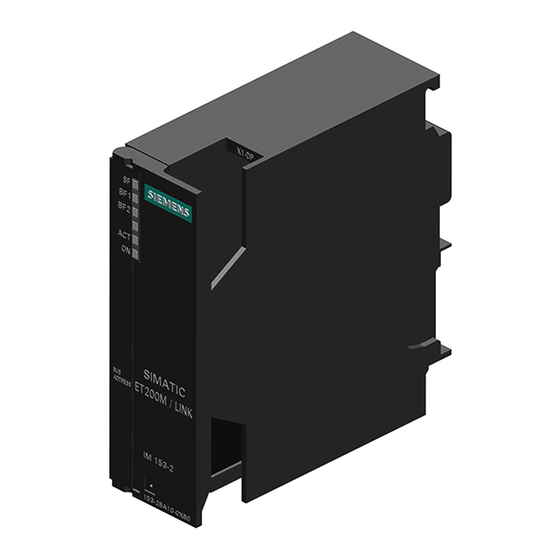
Siemens SIMATIC ET 200M Operating Instructions Manual

Siemens SIMATIC ET 200M Operating Instructions Manual

Distributed i/o device
Hide thumbs Also See for SIMATIC ET 200M:

Advertisement

DATASHEET
SIEMENS
6ES7 153-1AA03-0XB0
OTHER SYMBOLS:
RGB ELEKTRONIKA AGACIAK CIACIEK
SPÓŁKA JAWNA
Jana Dlugosza 2-6 Street
51-162 Wrocław
Poland
biuro@rgbelektronika.pl
+48 71 325 15 05
www.rgbautomatyka.pl
www.rgbelektronika.pl
www.rgbautomatyka.pl

Advertisement

loading

Summary of Contents for Siemens SIMATIC ET 200M

  • Page 1 DATASHEET SIEMENS 6ES7 153-1AA03-0XB0 OTHER SYMBOLS: RGB ELEKTRONIKA AGACIAK CIACIEK SPÓŁKA JAWNA Jana Dlugosza 2-6 Street 51-162 Wrocław www.rgbelektronika.pl Poland biuro@rgbelektronika.pl +48 71 325 15 05 www.rgbautomatyka.pl www.rgbautomatyka.pl www.rgbelektronika.pl...
  • Page 2 YOUR PARTNER IN MAINTENANCE Repair this product with RGB ELEKTRONIKA ORDER A DIAGNOSIS LINEAR ENCODERS SYSTEMS INDUSTRIAL COMPUTERS ENCODERS CONTROLS SERVO AMPLIFIERS MOTORS MACHINES OUR SERVICES POWER SUPPLIERS OPERATOR SERVO PANELS DRIVERS At our premises in Wrocław, we have a fully equipped servicing facility. Here we perform all the repair works and test each later sold unit.
  • Page 3 Preface SIMATIC Distributed I/O device ET00M ______________ Product overview Brief instructions on ______________ commissioning SIMATIC ______________ Assignment planning Distributed I/O device ______________ ET 200M Installation ______________ Connecting Operating Instructions ______________ Commissioning ______________ Maintenance and service The following supplement is part of this documentation: ______________ Edition Product Information...
  • Page 4 Note the following: WARNING Siemens products may only be used for the applications described in the catalog and in the relevant technical documentation. If products and components from other manufacturers are used, these must be recommended or approved by Siemens. Proper transport, storage, installation, assembly, commissioning, operation and maintenance are required to ensure that the products operate safely and without any problems.
  • Page 5 IM 153-1 /-2, refer to the "S7-300 automation system, module specifications (http://support.automation.siemens.com/WW/view/en/8859629)" Reference Manual. With the IM 153-x in the latest version we reserve the right to enclose a product information bulletin containing up-to-date information regarding the respective IM 153-x interface module or the operating instructions.
  • Page 6 Preface Changes since the previous version The following changes have been made since the previous version of these operating instructions "ET 200M distributed IO device" with the drawing number EWA-4NEB780600601-07, version 02/2006: The IM 153-4AA01 interface module offers the following new functions: ●...
  • Page 7 SIMATIC S7 and the ET 200 distributed I/O system. The description of the parameter assignment and configuration message frame is not a constituent part of these operating instructions. You will find a description of this on the Internet (http://support.automation.siemens.com/WW/view/en/1455647). ET 200M Operating Instructions, 12/2008, EWA-4NEB780600602-08...
  • Page 8 On account of its low level of contaminants, the ET 200M is suitable for recycling. Contact a certified electronic-waste disposal company to recycle and dispose of your old equipment in an environment-friendly manner. Contacts See product information "Technical Support, Contacts and Training (http://support.automation.siemens.com/WW/view/en/19293011)." Training See product information "Technical Support, Contacts and Training (http://support.automation.siemens.com/WW/view/en/19293011)." SIMATIC Technical Support See product information "Technical Support, Contacts and Training...
  • Page 9 Table of contents Preface ..............................3 Product overview ............................. 11 What Are Distributed I/O Devices ....................11 What is PROFIBUS DP?......................11 What is PROFINET IO? .......................13 ET 200M distributed I/O device....................14 IM 153-x: Variants and properties....................17 Brief instructions on commissioning......................21 Commissioning on PROFIBUS DP....................21 2.1.1 Introduction ..........................21...
  • Page 10 Table of contents Installation ............................... 59 Overview ............................. 59 Installation ........................... 59 4.2.1 Mounting Sequence ........................59 4.2.2 Installing the DIN rail ........................60 4.2.3 Installing modules on the mounting rail (standard installation) ........... 63 4.2.4 Installing Active Bus Modules and Modules (Configuration with Active Bus Modules) ....66 4.2.5 After installation...........................
  • Page 11: Direct Data Exchange

    Table of contents 7.10 Updating the IM 153-x........................117 7.10.1 When should you update the IM 153-x? ..................117 7.10.2 Update of the IM 153-1 / -2Ax0x ....................117 7.10.3 Update of the IM 153-2Bx00 ......................118 7.10.4 How to update the IM 153-2Bxx1....................122 7.11 Saving data and updating the IM 153-4 PN................124 Functions ...............................
  • Page 12 Table of contents Interrupt, error and system messages ....................185 PROFIBUS DP.......................... 185 9.1.1 Diagnostics with LED display ....................185 9.1.2 Diagnosis with STEP 7 or STEP 5.................... 188 9.1.3 Structure of the diagnosis ......................191 9.1.3.1 Structure of slave diagnosis ...................... 191 9.1.3.2 Station statuses 1 to 3.......................
  • Page 13 Product overview What Are Distributed I/O Devices Area of application When a system is set up, it is common for the inputs to and outputs from the process to be incorporated centrally in the automation system. If there are inputs and outputs at considerable distances from the programmable controller, there may be long runs of cabling which are not easy to follow, and electromagnetic interference may impair reliability.
  • Page 14 Product overview 1.2 What is PROFIBUS DP? Which devices can be connected to PROFIBUS DP? The most varied devices can be connected as DP masters or DP slaves to the PROFIBUS DP, the only proviso is that they behave in accordance with the standard IEC 61784-1:2002 Ed1 CP 3/1.
  • Page 15 Product overview 1.3 What is PROFINET IO? What is PROFINET IO? Definition PROFINET IO is an open transmission system with real-time functionality defined in accordance with the PROFINET standard. This standard defines a manufacturer- independent communication, automation and engineering model. Accessories for wiring the PROFINET components are available in industrial quality.
  • Page 16 In the module catalog or in the GSD file you will find a list of the modules that you can use in the ET 200M. For the current GSD file, go to Internet (http://support.automation.siemens.com/WW/view/en/113498). ET 200M Operating Instructions, 12/2008, EWA-4NEB780600602-08...
  • Page 17 Product overview 1.4 ET 200M distributed I/O device "SIMATIC S7-DP-Slave" The ET 200M distributed I/O system is a constituent part of the SIMATIC S7 automation system. STEP 7 In other words, provides support when configuring, assigning parameters to and programming the ET 200M in the DP master system as well as for the commissioning and diagnostics.
  • Page 18 Product overview 1.4 ET 200M distributed I/O device Components Function Diagram IM 153-x ... is the interface module; links the S7-300 modules to the PROFIBUS DP / Accessories: PROFINET IO; supplies the backplane Slot number plate (for the assignment of slot •...
  • Page 19: Enhanced Diagnostics

    Product overview 1.5 IM 153-x: Variants and properties See also IM 153-x: Variants and properties (Page 17) Arrangement of the modules for the function "Change During Operation" and / or "Redundancy" (Page 44) IM 153-x: Variants and properties Brief overview of the different IM 153-x The IM 153-x contains interface modules for the signal modules (SM), function modules (FM) and communication processors (CP).
  • Page 20 Product overview 1.5 IM 153-x: Variants and properties Properties / functions 6ES7153-1AA.. 6ES7153-2Ax.. 6ES7153-2Bx00 6ES7153-2Bxx1 Clock synchronism – – identification and maintenance data (I&M – – data) (only I&A data) Update – – Direct data exchange with F-modules – – –...
  • Page 21 Product overview 1.5 IM 153-x: Variants and properties Front view of the IM 153-2Bx00 Figure 1-5 Front view of the IM 153-2Bx00 ET 200M Operating Instructions, 12/2008, EWA-4NEB780600602-08...
  • Page 22 Product overview 1.5 IM 153-x: Variants and properties Front view of the IM 153-2Bxx1 Figure 1-6 Front view of the IM 153-2Bxx1 ET 200M Operating Instructions, 12/2008, EWA-4NEB780600602-08...
  • Page 23 Brief instructions on commissioning Commissioning on PROFIBUS DP 2.1.1 Introduction Introduction The following simple example shows you how to commission the ET 200M step by step. ● Installing and wiring the ET 200M STEP 7 ● Configuring with ● Linking to the User Program ●...
  • Page 24 Power supply PS 307 ④ SM 322 ⑧ PROFIBUS cable with bus connector Order numbers for the example configuration Number Item Order number (Siemens) Mounting rail e.g. 6ES7390-1AE80-0AA0 PS 307 power supply with jumper e.g. 6ES7307-1BA00-0AA0 Interface module IM 153-2...
  • Page 25 Brief instructions on commissioning 2.1 Commissioning on PROFIBUS DP Number Item Order number (Siemens) Side cutters and wire stripping tools commonly available Tool for crimping wire-end ferrules commonly available Approx. Stranded wire with 1 mm cross section with commonly available...
  • Page 26 Brief instructions on commissioning 2.1 Commissioning on PROFIBUS DP 2.1.3 Wiring the ET 200M Mounting rail 1. Connect the rail to the protective conductor. An M6 screw is provided on the rail for this purpose. Minimum cross-section from the conductor to the protective conductor: 10 mm WARNING You could touch live wires if the power supply module PS 307 is switched on or the supply cable of the power supply is connected to the mains supply.
  • Page 27 Brief instructions on commissioning 2.1 Commissioning on PROFIBUS DP Front Connectors of the DI and DO 1. Open the front doors of the DI and DO. 2. Move the front connector to the wiring position: To do so, push a front connector into each DI and DO until it engages. The front connector still protrudes from the module in this position.
  • Page 28 Brief instructions on commissioning 2.1 Commissioning on PROFIBUS DP 2.1.4 Putting Hardware into Service Procedure 1. Use the PD cable to connect the PD to the DP master (MPI interface). Make sure that the terminating resistors in the connectors are switched on. Set the mode switch to STOP. 2.
  • Page 29 Brief instructions on commissioning 2.1 Commissioning on PROFIBUS DP 2.1.5 Configuring the ET 200M in the SIMATIC manager Procedure 1. Start the SIMATIC Manager and then set up a new project with a DP master (e.g. CPU 315-2 DP). In addition to OB 1 also create OB 82 for the project. 2.
  • Page 30 Brief instructions on commissioning 2.1 Commissioning on PROFIBUS DP 5. Set the following parameters: – in the dialog box DP slave properties for ET 200M adopt the default settings – in the dialog box DP slave properties for SM 321, slot 4 in the configuration table diagnosis: No load voltage yes Diagnostic alarm: Yes –...
  • Page 31 Brief instructions on commissioning 2.1 Commissioning on PROFIBUS DP 2.1.6 Creating a user program Procedure 1. Generate the user program in the LAD / STL / FAD Editor in the OB 1. Example: Reading in the inputs and activating an output Description U I 0.1 If input E 0.1 is set and...
  • Page 32 Brief instructions on commissioning 2.1 Commissioning on PROFIBUS DP 2.1.8 Evaluating diagnostic messages: Introduction In this example, you generate diagnostic messages by provoking errors in the ET 200M. In the event of an error, OB82 is started. Evaluate the start information in the OB 82. Tip: Call SFC 13 within OB 82 and evaluate the diagnostic frame.
  • Page 33 Commissioning on PROFINET IO You will find further information on the PROFIBUS IO in the following manuals: ● System Manual "PROFINET System Description (http://support.automation.siemens.com/WW/view/en/19292127)" ● "From PROFIBUS DP to PROFINET IO (http://support.automation.siemens.com/WW/view/en/19289930)" Programming Manual ET 200M Operating Instructions, 12/2008, EWA-4NEB780600602-08...
  • Page 34 Brief instructions on commissioning 2.2 Commissioning on PROFINET IO ET 200M Operating Instructions, 12/2008, EWA-4NEB780600602-08...
  • Page 35 In addition, the IM 153-2Bxx1 can be used as an interface module for the DP/PA-link or the Y-link. You will find additional information in the "DP/PA Link and Y Link bus links (http://support.automation.siemens.com/WW/view/en/1142696)" operating instructions. Structure variants in the non-outdoor area Using the existing hardware you can realize the combinations listed in the following table in the non-outdoor area.
  • Page 36 ● The IM 153-2Bxx1 is not just an interface module for the ET 200M, but also for the bus connections DP/PA-link and Y-link. For the configuration variant options please refer to the "DP/PA Link and Y Link bus links (http://support.automation.siemens.com/WW/view/en/1142696)" operating instructions. See also Compatibilities between the IM 153-x (Page 241)
  • Page 37 Assignment planning 3.2 Detecting the configuration variant by means of the IM 153-2 Detecting the configuration variant by means of the IM 153-2 During start-up, the IM 153-2 automatically detects which structure variant (ET 200M or DP/PA-link or Y-link) it is being used in. The IM 153 2 determines its functionality in accordance with this.
  • Page 38 PD / PC via the HART analog input module to the intelligent field devices and back again (the thick line indicates the communication path). For a detailed description, please refer to "S7-300 Automation Systems, ET 200M Ex I/O Modules (http://support.automation.siemens.com/WW/view/en/1096709)" in the device manual. ①...
  • Page 39 Assignment planning 3.3 Configuration possibilities for PROFIBUS DP Parameter assignment / operation of HART field devices The following is required for the parameter assignment / operation of HART field devices: ● EDD (for ET 200M) Version V1.1.8 or higher EDD (Electronic Device Description) is required to set up HART field devices. It is PDM Device Library included on the CD (as of Edition 2, dated 2007) supplied with PDM.
  • Page 40 Assignment planning 3.3 Configuration possibilities for PROFIBUS DP 3.3.3 Configurable FM in a configuration with IM 153-2 Example configuration with IM 153-2 and FM The following figure shows an example of an ET 200M with IM 153-2 and in each case two SM and two FM of the S7-300 I/O modules.
  • Page 41 S7-400 automation system with IM 467 FO as DP master ② ET 200M distributed I/O with IM 153-2 FO ③ FOC duplex cable For more information on network configuration and network components refer to the "SIMATIC NET PROFIBUS networks (http://support.automation.siemens.com/WW/view/en/1971286)" manual. ET 200M Operating Instructions, 12/2008, EWA-4NEB780600602-08...
  • Page 42 Note the general rules for the structure of an H system. You will find the general rules for the structure of an H system in the "S7-400H, – fault- tolerant systems (http://support.automation.siemens.com/WW/view/en/1186523)" system manual. Structure variants and configuration possibilities for PROFINET IO Structure variants and configuration possibilities for PROFINET IO can be found in the "PROFINET System Description...
  • Page 43 Assignment planning 3.5 Configuring the mechanical structure Permissible Ambient Temperature The following ambient temperature ranges are available: ● In horizontal mounting position: From 0°C to 60 °C ● In vertical mounting position: From 0°C to 40 °C When configuring the ET 200M with IM 153-1AA8x or IM 153-2BA8x (outdoor) and SIPLUS S7-300 modules the specified temperature range extends up to -25 °C.
  • Page 44 You will find the installation dimensions of the modules for the S7-300 spectrum in the "S7-300 automation system, module specifications (http://support.automation.siemens.com/WW/view/en/8859629)" reference manual. The installation dimensions of the IM 153-x interface module are specified in the "Technical specifications of the IM 153-x (Page 231)" chapter.
  • Page 45 370 between the IM 153-x and the modules in the intrinsically safe area. Only in this way can you adhere to the necessary thread measure (refer also to the reference manual "S7-300 Automation Systems, ET 200M Ex I/O Modules (http://support.automation.siemens.com/WW/view/en/1096709)"). ET 200M Operating Instructions, 12/2008, EWA-4NEB780600602-08...
  • Page 46: Redundancy 1

    Assignment planning 3.5 Configuring the mechanical structure 3.5.4 Arrangement of the modules for the function "Change During Operation" and / or "Redundancy" Arrangement rules The following rules apply to the location of the modules in an ET 200M: ● An ET 200M can only be installed on one mounting rack (rail), because coupling to other mounting racks via interface modules is not permissible.
  • Page 47 Assignment planning 3.5 Configuring the mechanical structure ● Use the rails for "module change during operation" (only these can take the active bus modules). ● Close unused slots with the backplane bus cover. Close the last bus module with the bus module cover.
  • Page 48 Assignment planning 3.5 Configuring the mechanical structure Installation Options Dependent on the length of the rails you can fit up to 9 active bus modules: Figure 3-9 Configuration with active bus modules Placement of the PS 307 power supply modules Redundancy with 2 x IM If you use the 530 mm rail, place the BM IM/IM in the right-hand of the 153-2...
  • Page 49 Assignment planning 3.6 Configuring the electrical structure Configuring the electrical structure 3.6.1 General rules and regulations for operating the ET 200M Introduction Depending on the particular area of application, the ET 200M programmable controller, as part of a plant or system, requires that you observe a number of specific rules and guidelines.
  • Page 50 Assignment planning 3.6 Configuring the electrical structure Supply voltage The following table identifies requirements to be observed for the line voltage. With ... the ... Stationary plants or systems without all- There must be a supply isolating switch or a fuse in the pole line voltage disconnect switch building installation system Load power supplies, power supply...
  • Page 51 Assignment planning 3.6 Configuring the electrical structure Rules on the Power Consumption and Power Loss of an ET 200M For their operation, the S7-300 modules use the necessary power from the backplane bus as well as, if necessary, from an external load power supply. ●...
  • Page 52 Assignment planning 3.6 Configuring the electrical structure 3.6.2 Operating the ET 200M with process I/O on a grounded supply The following gives information on the overall configuration of an ET 200M to a grounded supply (TN-S-network). The topics covered here are: ●...
  • Page 53 Safer (electrical) isolation Modules that must be supplied The power supplies PS 307 as with voltages ≤ DC 60 V or well as the Siemens load power ≤ AC 25 V supplies of the 6EP1 series have this property. 24 V DC load power supply...
  • Page 54 Assignment planning 3.6 Configuring the electrical structure ET 200M in the overall configuration The following figure shows the position of the ET 200M in the overall configuration (load power supply and grounding concept) with a supply from a TN-S-network. Note: The arrangement shown of the supply connections does not correspond to the actual arrangement;...
  • Page 55 Assignment planning 3.6 Configuring the electrical structure ET 200M with load power supply from the PS 307 The following figure shows the position of the ET 200M in the overall configuration (load power supply and grounding concept) with a supply from a TN-S-network. Alongside the IM 153-x, the PS 307 also supplies the load circuit for the 24 V DC modules.
  • Page 56 Assignment planning 3.6 Configuring the electrical structure 3.6.3 Configuration of an ET 200M with ungrounded reference potential In the configuration of the ET 200M with ungrounded reference potential, the occurring interference currents are deflected to the grounding wire via an RC network that is integrated in the IM 153-x (see following figure).
  • Page 57 Filtering the 24 V DC supply If, with a configuration with ungrounded reference potential, you supply the IM 153-x from a battery, you must suppress the 24 V DC power supply. To do this, use a Siemens mains filter, e.g. B84102-K40.
  • Page 58 Assignment planning 3.6 Configuring the electrical structure Configuration with isolated modules The following figure shows the potential relation of an ET 200M configuration with isolated input and output modules. Figure 3-13 Simplified representation for the configuration with isolated modules ET 200M Operating Instructions, 12/2008, EWA-4NEB780600602-08...
  • Page 59 Assignment planning 3.6 Configuring the electrical structure 3.6.5 Configuration of the ET 200M with non-isolated modules Potential relations in the configuration with isolated modules The following figure shows the potential relations of an ET 200M configuration with grounded reference potential with the isolated analog input / output module SM 334; AI 4/AO 2 x 8/8 bit.
  • Page 60 Assignment planning 3.6 Configuring the electrical structure ET 200M Operating Instructions, 12/2008, EWA-4NEB780600602-08...
  • Page 61 Installation Overview Introduction In this chapter we will show you how to prepare and install the ET 200M components. There are two configuration types for the ET 200M: ● Standard configuration with rail and bus connectors between the modules ● Configuration with active bus modules for the function "Change During Operation" and / or "Redundancy"...
  • Page 62 Installation 4.2 Installation 4.2.2 Installing the DIN rail Uniform Installation All the information in this section applies to both the DIN rail and the rail for active bus modules. Mounting Rail for Active Bus Module To configure an ET 200M with the function "Module change during operation", "Redundancy", use the associated rails with the order number 6ES7195-1Gxx0-0XA0.
  • Page 63 Installation 4.2 Installation Dimensioned Drawing for Fixing Holes The fixing-hole dimensions for the rail are shown in the following table. Table 4- 1 Fixing holes for rails DIN Rail Mounting rail for the "Insertion and Removal" function Length of rail DIN Rail Mounting rail for the Dimension a...
  • Page 64 Installation 4.2 Installation Fixing Screws You have a choice of the following screw types for fixing the rail. For … you can use ... Description Outer fixing screws Fillister head screw M6 in Choose a suitable screw length for accordance with your configuration.
  • Page 65 Installation 4.2 Installation Connection of protective conductor The following figure shows you how to connect the protective conductor to the rail. Figure 4-2 Connecting the protective conductor to the rail See also Clearance Measurements (Page 41) 4.2.3 Installing modules on the mounting rail (standard installation) Accessories The accessories you need for installation are included with the modules.
  • Page 66 If you are installing SM 331 analog input modules, please check before installation whether you have to move the measuring range submodules on the side of the module. (Refer to chapter "Analog modules" in the "S7-300 automation system, module specifications (http://support.automation.siemens.com/WW/view/en/8859629)" reference manual.) Sequence for Installation...
  • Page 67 Installation 4.2 Installation Step Activity Figure Hook the modules onto the rail (1), slide them along as far as the module on the left (2), and swing them down into place (3). Bolt the modules tight, applying a torque of between 0.8 and 1.1 Nm.
  • Page 68 Installation 4.2 Installation 4.2.4 Installing Active Bus Modules and Modules (Configuration with Active Bus Modules) Installing Bus Modules and Modules To install the active bus modules and modules, proceed as follows: Only install the active bus modules in a de-energized state. 1.
  • Page 69 Installation 4.2 Installation Rail for active bus module The figure below shows the dimensioned drawing of the rail with active bus module, S7-300 module and explosion-proof partition. The rail is 482.6 mm or 530 mm long. ① Explosion-proof partition ② S7-300 module ③...
  • Page 70 Installation 4.2 Installation 4.2.5 After installation Assign slot numbers After installation you can assign a slot number to each module, and this makes it easier to STEP 7 COM PROFIBUS assign the modules to the configuration table in or in .
  • Page 71 Installation 4.3 Setting the PROFIBUS address Setting the PROFIBUS address Definition Each bus node must receive a PROFIBUS address to identify it uniquely on the PROFIBUS Controlling The following rules apply for the PROFIBUS address of the IM 153-x: ● Permissible PROFIBUS addresses are: 1 to 125. ●...
  • Page 72 Installation 4.3 Setting the PROFIBUS address Changing the PROFIBUS Address You can change the set PROFIBUS address at any time. However, the IM 153-x adopts the new PROFIBUS address only after a switch off / switch on of the 24 V DC supply. ET 200M Operating Instructions, 12/2008, EWA-4NEB780600602-08...
  • Page 73 Connecting Overview Introduction This chapter shows you how to wire an ET 200M. To set up an ET 200M, you must take into account the mechanical and electrical configuration. Information can be found in the "Assignment Planning (Page 33)" chapter. Basic Rules In view of the many and varied applications of an ET 200M, this chapter can only describe a few basic rules on its electrical configuration.
  • Page 74 Connecting 5.2 Connecting PROFIBUS DP ● up to 12 MBaud, with vertical cable departure – without PD jack (6ES7972-0BA12-0XA0) – with PD jack (6ES7972-0BB12-0XA0) ● up to 12 MBaud, with diagonal cable departure – without PD jack (6ES7972-0BA41-0XA0) – with PD jack (6ES7972-0BB41-0XA0) Connecting the Bus Connector Proceed as follows to connect the bus connector: 1.
  • Page 75 2. Install the FOC duplex cable with the associated Simplex connectors. For detailed assembly instructions for simplex connectors, refer to the"SIMATIC NET PROFIBUS networks (http://support.automation.siemens.com/WW/view/en/1971286)" manual. IMPORTANT: The cut and polished surface of the plastic fiber must be absolutely smooth and even.
  • Page 76 When inserting the FOC duplex wire in the plug adapter and when laying, ensure that the associated bending radius of 30 mm is not fallen short of. See also the installation guidelines on fiber-optic cables in the "ET 200 Distributed I/O System (http://support.automation.siemens.com/WW/view/en/1142470)" or "ET 200 Distributed I/O System (http://support.automation.siemens.com/WW/view/en/1142470)" manuals. ET 200M...
  • Page 77 Connecting 5.3 Connecting PROFINET IO Connecting PROFINET IO 5.3.1 Connecting IM 153-4 PN Introduction You connect the supply voltage and PROFINET IO to the IM 153-4 PN interface module. ① Front door ② Connection for PROFINET IO (with 2 ports) ③...
  • Page 78 Connecting 5.3 Connecting PROFINET IO Required accessories ● Cable with maximum 2.5 mm conductor cross section for the supply voltage ● PROFINET connector according to the specifications in the "PROFINET installation guideline (http://www.profibus.com/pall/meta/downloads/article/00328/)". The following are suitable: PROFINET RJ45 connector with 6GK1901-1BB10-2AA0 Fast Connect connection system, 180°...
  • Page 79 Connecting 5.3 Connecting PROFINET IO Connecting PROFINET IO and supply voltage 1. Connecting PROFINET IO – Insert the PROFINET cable connector onto the PROFINET terminal X1 P1. – Clamp the PROFINET cable securely in the cableholder. The integrated switch enables looping through of PROFINET IO. If necessary, you can connect the PROFINET terminal X1 P2 to another IO device.
  • Page 80 Connecting 5.4 Wiring the power supply and modules Wiring the power supply and modules 5.4.1 Wiring rules Note For a configuration for "Module change during operation", provide longer cables to the front connectors (refer to chapter "Wiring front connectors of the signal modules (Page 81)"). Table 5- 1 Wiring rules for the power supply and the IM 153-x Wiring rules for ...
  • Page 81 Connecting 5.4 Wiring the power supply and modules 5.4.2 Wiring the Power Supply and IM 153-x Power Cables Use flexible cables to wire the power supply. If you use only one cable per connection, you don't need an end ferrule. Jumper Use the jumper to wire the power supply module PS 307 with the IM 153-x.
  • Page 82 Connecting 5.4 Wiring the power supply and modules Wiring a power supply and IM 153-x with jumper In order to wire power supply modules and IM 153-x, proceed as follows (refer to the following figure): WARNING Ensure the ET 200M is de-energized before doing any wiring! 1.
  • Page 83 S7-Ex-modules For information on how to wire the S7-Ex-modules and what you should observe when wiring modules in the intrinsically safe area, refer to the "S7-300 Automation Systems, ET 200M Ex I/O Modules (http://support.automation.siemens.com/WW/view/en/1096709)" reference manual. Cables You can use the flexible cables with cross-sections as specified in the "Wiring rules (Page 78)"...
  • Page 84 Connecting 5.4 Wiring the power supply and modules Preparing the Connector for Wiring To prepare for wiring, proceed as follows: WARNING You can come into contact with live cables if the power supply module and possibly in addition the load power supplies are switched on. Ensure the ET 200M is de-energized before doing any wiring! 1.
  • Page 85 Connecting 5.4 Wiring the power supply and modules Wiring front connectors Table 5- 3 Wiring front connectors Step 20-pin front connector 40-pin front connector Thread the cable strain relief assembly into the – front connector. Do you want to bring the cables out at the bottom of the module? If so: Start with terminal 20 and wire the terminals in the Start with terminal 40 or 20 and continue to wire the...
  • Page 86 Connecting 5.4 Wiring the power supply and modules Preparing the signal module for operation Table 5- 4 Preparing the signal module for operation Step 20-pin front connector 40-pin front connector Press down the unlocking button on the top of the Tighten screws to bring front connector to its operating module and, at the same time, push the front position.
  • Page 87 Connecting 5.4 Wiring the power supply and modules 5.4.4 Connecting shielded cables via a shield connecting element Introduction This section tells you how to connect the shield of shielded signal lines to ground via a shield contact element. The connection to ground is achieved by direct contact between the shield contact element and the rail.
  • Page 88 Connecting 5.4 Wiring the power supply and modules Installing the Shield Contact Element Install the shield contact element as follows: 1. Push the two bolts of the fixing bracket into the guide on the underside of the rail. Position the fixing bracket under the modules to be wired. 2.
  • Page 89 Connecting 5.4 Wiring the power supply and modules Attaching Cables You can only attach one or two shielded cables per shield terminal (see figure and table above). The cable is connected by its bare cable shield. There must be at least 20 mm of bare cable shield.
  • Page 90 Connecting 5.4 Wiring the power supply and modules ET 200M Operating Instructions, 12/2008, EWA-4NEB780600602-08...
  • Page 91 DP master Refer to chapter "PROFIBUS DPV1 operation (Page 95)" to find out which functions can be operated with the individual GSD revisions. For the current GSD file, go to Internet (http://support.automation.siemens.com/WW/view/en/113498). ET 200M Operating Instructions, 12/2008, EWA-4NEB780600602-08...
  • Page 92 Commissioning 6.1 PROFIBUS DP Requirements for commissioning The following conditions must be fulfilled in order to commission the ET 200M: ● DP slave installed ● PROFIBUS address set on the DP slave ● Bus connector or FOC is connected ● Only for DP interface RS 485: If the DP slave is located on the end of the segment, then the terminating resistor is switched on the DP slave.
  • Page 93 Commissioning 6.1 PROFIBUS DP 6.1.2 IM 153-1 start-up Figure 6-1 Start-up of the IM 153 1 Figure 6-2 Startup behavior in the case of module change during operation ET 200M Operating Instructions, 12/2008, EWA-4NEB780600602-08...
  • Page 94 Commissioning 6.1 PROFIBUS DP 6.1.3 IM 153-2 / 153-2 FO start-up Declaration The term IM 153-2 applies in this chapter to: IM 153-2 and IM 153-2 FO Declaration in the case of redundancy: In the case of redundancy the 2 plugged IM 153-2 start up independently from each other. The following flow chart takes into consideration the start-up of the IM 153-2 (a).
  • Page 95 Commissioning 6.1 PROFIBUS DP Start-up of the IM 153-2 Figure 6-3 Start-up of the IM 153-2 ET 200M Operating Instructions, 12/2008, EWA-4NEB780600602-08...
  • Page 96 Commissioning 6.1 PROFIBUS DP Start-up for time synchronization / time stamp of the signal changes Figure 6-4 Start-up for time synchronization / time stamping ET 200M Operating Instructions, 12/2008, EWA-4NEB780600602-08...
  • Page 97 Commissioning 6.1 PROFIBUS DP 6.1.4 PROFIBUS DPV1 operation The ET 200M fulfils the requirements in accordance with DPV1. If you wish to use the DPV1 functions, then the DP master must of course fulfill the requirements in accordance with DPV1 (refer to the DP master documentation). Functions of the PROFIBUS DPV1 slave The following table shows you the new functions of the PROFIBUS DPV1 slave compared with a PROFIBUS DPV0 slave:...
  • Page 98 Commissioning 6.2 PROFINET IO Actions after the diagnostics message in the S7 or DPV1 mode Actions initiated by diagnostic messages: ● With S7 or DPV1 operation the diagnoses are reported as diagnostic interrupts. ● In DPV1 mode, diagnoses are also reported when the master CPU is in STOP. In the diagnostic frame in addition the module status and the channel-related diagnoses are available.
  • Page 99 To do so you must install the GSD in the configuration software beforehand. Requirements You will need a GSD file, available for download from the Internet (http://support.automation.siemens.com/WW/view/en/25057900). Interface Module IM 153-4 PN: GSDML-V1.0-Siemens-ET200M-"date in yyyymmdd format".xml STEP 7 Configuring the ET 200M on PROFINET IO with STEP 7 1. Start and then select the Tools >...
  • Page 100 For configuration and in the user program, each ET 200M IO device is addressed with its device name. For detailed information on addressing in PROFINET IO, refer to the "PROFINET System Description (http://support.automation.siemens.com/WW/view/en/19292127)" system manual. Requirements ● Interface Module IM 153-4 PN ●...
  • Page 101 Commissioning 6.2 PROFINET IO Forwarding the device name on replacement of the interface module The device name of the IO device is saved on the SIMATIC Micro Memory Card for IM 153- 4AA00-0XB0. As of IM153-4AA01-0XB0, you can save the device name as previously on a SIMATIC Micro Memory Card or optionally in the interface module.
  • Page 102 Commissioning 6.2 PROFINET IO 6.2.4 Configuring ports of the IM 153-4 PN Introduction The IM 153-4 PN interface module can diagnose both of its ports: X1 P1 and X1 P2. Requirement ● The ports must be configured in HW Config. ●...
  • Page 103 Commissioning 6.2 PROFINET IO 6.2.5 Commissioning ET 200M for PROFINET IO Introduction Your automation system is commissioned depending on the current plant configuration. The following procedure describes the commissioning of the ET 200M on an I/O controller. Requirements for the ET 200M on PROFINET IO Actions Reference ET 200M installed...
  • Page 104 Commissioning 6.2 PROFINET IO 6.2.6 Startup of ET 200M on PROFINET IO Principle of operation The diagram below shows the startup sequence of the ET 200M on PROFINET IO: Figure 6-5 Startup of ET 200M on PROFINET IO ET 200M Operating Instructions, 12/2008, EWA-4NEB780600602-08...
  • Page 105 Maintenance and service Wiring of the ET 200M Scope of maintenance The ET 200M is a maintenance-free DP slave. Maintenance is limited to the replacement or exchanging of modules or components. Replacing the Power Supply Module Initial Situation The power supply module you want to replace is installed and wired. You want to install a new power supply module of the same type.
  • Page 106 Maintenance and service 7.3 replacing the IM 153-1 Response of the ET 200M After Module Replacement STEP 5 STEP 7 If there is an error after replacing the module, with you can view the cause of the error in the diagnostics buffer. replacing the IM 153-1 Initial Situation The IM 153-1 is installed.
  • Page 107 Maintenance and service 7.4 Replacing the IM 153-2 or IM 153-2 FO Installing a New Module Install the new module as follows: 1. On the IM 153-1 set the same DP address as you had on the old IM 153-1. 2.
  • Page 108 Maintenance and service 7.4 Replacing the IM 153-2 or IM 153-2 FO IM 153-2 FO: Removing the fiber-optic cable When you remove the FOC from the IM 153-2 FO, then all following DP slaves are also no longer available for the DP master! CAUTION Do not look directly into the opening of the optical transmit diodes.
  • Page 109 Maintenance and service 7.4 Replacing the IM 153-2 or IM 153-2 FO Removing a Module To remove the module, proceed as follows: 1. In the Case of Redundancy: The IM 153 -2 / -2 FO that is to be replaced must always be deactivated! Switch off the assigned power supply module or disconnect it on the IM 153 -2 / -2 FO.
  • Page 110 In this case, you must switch off the ET 200M and update both IM 153-2 / -2 FO or use a compatible version. Contact your Siemens representative. See also Diagnostics with LED display (Page 185)
  • Page 111 Maintenance and service 7.5 Replacing IM 153-4 PN Replacing IM 153-4 PN Initial situation The IM 153-4 PN is installed. A new IM 153-4 PN of the same type should be installed. Slot numbering If you have provided the modules in your system with slot numbering, when replacing modules you must remove the numbering from the old module and then reuse it in the new module.
  • Page 112 Maintenance and service 7.6 Replace modules without the function "Change During Operation" Replacement for IM 153-4 PN (order number 6ES7153-4AA01-0XB0) The IM153-4AA01 interface module is compatible with the IM153-4AA00 interface module and can replace this. If a replacement is necessary, an IO device already in operation in has to be reset to the STEP 7 factory settings by using "Reset to factory settings"...
  • Page 113 Maintenance and service 7.6 Replace modules without the function "Change During Operation" Removing the Front Connector Coding Key Prior to installing the new module, you must remove the front connector coding key from the new module. Reason: This part is already available in the wired front connector (refer to the following figure).
  • Page 114 Maintenance and service 7.6 Replace modules without the function "Change During Operation" Putting a New Module into Service Put the new modules into service as follows: 1. Open the front door. 2. Bring the front connector back into its operating position. 3.
  • Page 115 Maintenance and service 7.7 Replace modules with the function "Change During Operation" Replace modules with the function "Change During Operation" Requirements You can replace the modules while operating the ET 200M if the ET 200M ● on the rail with active bus modules for the function "Module Change During Operation" ●...
  • Page 116 Maintenance and service 7.7 Replace modules with the function "Change During Operation" Remove the front connector encoding device Prior to installing the new module you must remove the top part of the front connector encoding on the module. Reason: This part is already available in the wired front connector (refer to the following figure).
  • Page 117 Maintenance and service 7.8 Replacing the bus module Replacing the bus module Removing the bus module Only remove bus modules if they are de-energized! Proceed as follows when removing the bus module: 1. With the on / off switch of the power supply module to 0 : output voltages 0 V).
  • Page 118 Maintenance and service 7.9 Exchanging fuses in digital output modules Exchanging fuses in digital output modules Fuses for Digital Outputs The digital outputs of the following digital output modules are safeguarded (in channel groups) against a short circuit by means of uses: ●...
  • Page 119 After performance or (compatible) function enhancements you should update the interface module IM 153-x to the latest firmware version. 7.10.2 Update of the IM 153-1 / -2Ax0x Please contact your Siemens representative if you wish to update the IM 153-1 and the IM 153-2Ax0x. ET 200M Operating Instructions, 12/2008, EWA-4NEB780600602-08...
  • Page 120 7.10.3 Update of the IM 153-2Bx00 Where can I obtain the latest firmware version? You can order the latest firmware from your Siemens partner, or download it from the Internet (http://support.automation.siemens.com/WW/view/en/15350678). Tip: ● Prior to the update note down the current version of your firmware.
  • Page 121 Maintenance and service 7.10 Updating the IM 153-x Example configuration Update from PD / PC via PROFIBUS DP (direct) The PG / PC with the update files is directly connected to the PROFIBUS interface of the IM 153-2 (refer to the following figure). Note If no STEP 7 project containing the respective IM 153-2 is available, then the update can STEP 7...
  • Page 122 Maintenance and service 7.10 Updating the IM 153-x Carry out an update via SIMATIC Micro Memory Card as follows: STEP 7 1. Use and your programming device to transfer the update files to a SIMATIC Micro Memory Card. The data saved on the SIMATIC Micro Memory Card is then overwritten by the update files.
  • Page 123 Maintenance and service 7.10 Updating the IM 153-x Restart After Update Update via PROFIBUS DP STEP 7 In the user interface, it is possible to set whether ● the IM 153-2 should automatically perform a reset after a successful update, in order to start off using the new firmware.
  • Page 124 Maintenance and service 7.10 Updating the IM 153-x 7.10.4 How to update the IM 153-2Bxx1 Where can I obtain the latest firmware version? You can order the latest firmware from your Siemens partner, or download it from the Internet (https://portal.automation.siemens.com/apps/meta- search_p/index.ad.nwa.EN.html?q=15350678). Tip: ●...
  • Page 125 Maintenance and service 7.10 Updating the IM 153-x Conditions for an update via PROFIBUS DP ● The IM 153-2 in the station that is to be updated must be available online. ● The files with the current (new) version of the firmware must be available in the file system of your PD / PC.
  • Page 126 Maintenance and service 7.11 Saving data and updating the IM 153-4 PN 7.11 Saving data and updating the IM 153-4 PN Storage medium A SIMATIC Micro Memory Card is used as the storage medium for the IM 153-4 PN. The MMC can be used as a portable data medium.
  • Page 127 Position of the module slot for the SIMATIC Micro Memory Card on the IM 153-4 PN Where can I obtain the latest firmware version? You can order the latest firmware from your Siemens partner, or download it from the Internet (http://support.automation.siemens.com/WW/llisapi.dll?func=cslib.csinfo2&aktprim=99&lang=...
  • Page 128 Maintenance and service 7.11 Saving data and updating the IM 153-4 PN Principle An update is possible with IM 153-4 PN as of order number 6ES7153-4AA00-0XB0. For this STEP 7 you require V5.4 SP 2 or higher. There are two ways of updating: ●...
  • Page 129 Maintenance and service 7.11 Saving data and updating the IM 153-4 PN Example configuration Update from PD / PC via PROFINET IO (direct) The PG / PC with the update files is directly connected to the PROFINET interface of the IM 153-4 PN (refer to the following figure).
  • Page 130 Maintenance and service 7.11 Saving data and updating the IM 153-4 PN 4. Insert the SIMATIC Micro Memory Card containing the update in the module slot. 5. Switch on the power. – The IM 153-4 PN automatically detects the SIMATIC Micro Memory Card with the update files and starts the update.
  • Page 131 Functions Support for I/O modules with expanded input data The IM 153-2BAx2 interface module supports I/O modules with expanded input data (> 16 bytes). For more detailed information, refer to the documentation on the respective modules. Expanded output data are not supported. For the ET 200M, this means that: ●...
  • Page 132 You´ll find a detailed description for time stamping with 10 ms precision and for time synchronization in the PCS 7 function manual "Process control system PCS 7 10 ms time stamping (http://support.automation.siemens.com/WW/view/en/15231179)". ● outside of an S7-400 automation system, with precisions of up to 1 ms...
  • Page 133 Functions 8.2 Time stamping the input signals with IM 153-2 Marginal conditions The precision of the time stamping is influenced by the following marginal conditions: ● The number of time-stamped input signals in an ET 200M influences the precision of the time stamping, e.g.
  • Page 134 Functions 8.2 Time stamping the input signals with IM 153-2 Parameter assignment With the configuration you establish which digital input data of the IM 153-2 is going to be monitored. For the time stamping, these are signal changes on the digital inputs. Two signal edges are always stamped.
  • Page 135 Functions 8.2 Time stamping the input signals with IM 153-2 Example structure for time stamping signal changes with IM 153-2 ① Operator station (OS) for unit visualization ② Industrial Ethernet ③ Time sender (SICLOCK) ④ ET 200M Distributed I/O ⑤ SM 321 digital input module (6ES7321-7BH…) ⑥...
  • Page 136 Functions 8.2 Time stamping the input signals with IM 153-2 8.2.2.2 Highly precise time stamp with 1 ms precision Controlling The following configuration must be authorized for the highly precise time stamping with 1 ms precision: ● Automation system with highly precise time synchronization To do this a clock master, e.g.
  • Page 137 Functions 8.2 Time stamping the input signals with IM 153-2 8.2.2.3 Time synchronization for time stamping Requirements The following requirements apply to the time synchronization for time stamping: ● There must be a clock master, e.g. SICLOCK TM available in the automation system. It must work with synchronization intervals of 10 s.
  • Page 138 Functions 8.2 Time stamping the input signals with IM 153-2 ● Ethernet: CP 443-1 as of FW V2.6; 6GK7443-1EX11-0XE0 Parameters to be set for Ethernet CP: Parameter Value Forward time from LAN to station Switch on the time synchronization in SIMATIC procedure ●...
  • Page 139 Functions 8.2 Time stamping the input signals with IM 153-2 Setting example Figure 8-2 SICLOCK TM parameter menu Figure 8-3 CP 443-1 properties ET 200M Operating Instructions, 12/2008, EWA-4NEB780600602-08...
  • Page 140 Functions 8.2 Time stamping the input signals with IM 153-2 Figure 8-4 CP 443-5 Extended properties Figure 8-5 CPU properties ET 200M Operating Instructions, 12/2008, EWA-4NEB780600602-08...
  • Page 141 Functions 8.2 Time stamping the input signals with IM 153-2 Figure 8-6 DP slave properties ET 200M Operating Instructions, 12/2008, EWA-4NEB780600602-08...
  • Page 142 This time is communicated by the special message "Changeover with redundant BEGIN / END". You will find more information on time stamping in redundant systems in the "PCS 7 documentation (http://support.automation.siemens.com/WW/view/en/10806846/130000)" documentation. ① WinCC Operator station (OS) for unit visualization ②...
  • Page 143 ● WinCC for the visualization You´ll find a detailed description for time stamping with 10 ms precision and for time synchronization in the "Process control system PCS 7 10 ms time stamping (http://support.automation.siemens.com/WW/view/en/15231179)" manual. ET 200M Operating Instructions, 12/2008, EWA-4NEB780600602-08...
  • Page 144 Functions 8.2 Time stamping the input signals with IM 153-2 Example structure for time stamping signal changes with IM 153-2 ① WinCC Operator station (OS) for unit visualization ② Industrial Ethernet ③ Time master (SICLOCK) ④ ET 200M Distributed I/O ⑤...
  • Page 145 Functions 8.2 Time stamping the input signals with IM 153-2 8.2.4 Time stamping outside of S7-400 8.2.4.1 Prerequisites With the interface module IM 153-2Bxx1, time stamping is also possible outside of an S7- 400 automation system. The above principles and rules apply - if complied with, precisions of up to 1 ms can be achieved.
  • Page 146 Functions 8.2 Time stamping the input signals with IM 153-2 Sample configuration: Integrated DP master forwards the time received by the CPU ① Operator station (OS) for unit visualization ② Industrial Ethernet ③ CPU with integrated clock as clock master •...
  • Page 147 Functions 8.2 Time stamping the input signals with IM 153-2 Sample configuration: Communication processor as DP master and DP clock master ① Operator station (OS) for unit visualization ② Industrial Ethernet ③ Time master e.g. SICLOCK ④ ⑤ Communication processor for connection to an Industrial Ethernet ⑥...
  • Page 148 Functions 8.2 Time stamping the input signals with IM 153-2 Sample configuration: Communication processor as DP master as well as a separate time master ① Operator station (OS) for unit visualization ② Industrial Ethernet ③ ④ Communication processor for connection to an Industrial Ethernet ⑤...
  • Page 149 Functions 8.2 Time stamping the input signals with IM 153-2 8.2.4.2 Operating principle ● The 240 data record is the configured data record for the time stamping on the ET 200M. It defines which modules and which input channels of which type can be called upon by the IM 153-2 for the time stamping.
  • Page 150 Functions 8.2 Time stamping the input signals with IM 153-2 Order of events Figure 8-13 Processing time-stamped signals ET 200M Operating Instructions, 12/2008, EWA-4NEB780600602-08...
  • Page 151 PROFIBUS DP, is obtained by your DP master from the GSD file. The GSD file for the IM 153-2BAx1 can be found in the Internet (http://support.automation.siemens.com/WW/view/e n/113498). Integrate the slave with the DP Add the IM 153-2 to the DP line of your master master.
  • Page 152 Functions 8.2 Time stamping the input signals with IM 153-2 Step Activity Description Diagnose imminent signal When signal messages arrive the slave sends a messages and save the process interrupt to the master. The master then information. asks for a diagnosis from the slave. Ensure that when a process The slave responds with the diagnostic frame.
  • Page 153 Functions 8.2 Time stamping the input signals with IM 153-2 Structure of the data record 240 for configuring the time stamp of the input signals The telegram with the data record DS 240 has 4 bytes head data: Figure 8-14 Head data of the telegram with the data record 240 for the configuration ET 200M Operating Instructions, 12/2008, EWA-4NEB780600602-08...
  • Page 154 Functions 8.2 Time stamping the input signals with IM 153-2 The configuration data in the data record 240 for configuring the time stamp is structured as follows: Figure 8-15 Structure of the data record 240 for the configuration ET 200M Operating Instructions, 12/2008, EWA-4NEB780600602-08...
  • Page 155 Functions 8.2 Time stamping the input signals with IM 153-2 The configuration data in the data record 240 for configuring the time stamp for IM 153-2BAx2 is structured as follows: Figure 8-16 IM 153-2BAx2: Structure of data record 240 for parameter assignment ET 200M Operating Instructions, 12/2008, EWA-4NEB780600602-08...
  • Page 156 Functions 8.2 Time stamping the input signals with IM 153-2 Parameterizing the edges ● Time stamp with edge 0 → 1: With a signal change on the digital input of 0 → 1 a signal message with signal status 80h (incoming) is stored in the data record (DS 100 to 114).
  • Page 157 Functions 8.2 Time stamping the input signals with IM 153-2 Value Meaning Status of time stamping Data record number of the data record to be fetched (64h to 72h = DS 100 … 114) Number of messages in the data record (01h to 14h = 1 …...
  • Page 158 Functions 8.2 Time stamping the input signals with IM 153-2 8.2.4.7 Structure of the IM 153-2 messages The IM 153-2 makes available 15 data records for saving stamped input signals (signal messages) and special messages (DS 100 to DS 114). A maximum of 20 signal and special messages each consisting of 12 bytes can be saved in a data record.
  • Page 159 Functions 8.2 Time stamping the input signals with IM 153-2 Structure of a special message A special message always comes from the IM 153-2 (slot 2). It is structured as follows: Table 8- 7 Structure of a special message Meaning Number of Remarks bytes...
  • Page 160 Functions 8.2 Time stamping the input signals with IM 153-2 8.2.4.8 Significance of special messages With an activated time stamping, the IM 153-2 can supply the following special messages: ● If all 15 data records of the IM 153-2 are full, then the IM 153-2 cannot save any further messages.
  • Page 161 Functions 8.2 Time stamping the input signals with IM 153-2 Structure of the data record 240 for the diagnosis The diagnosis data in the data record 240 for diagnosing the time stamp is made up of 80 bytes is structured as follows: ET 200M Operating Instructions, 12/2008, EWA-4NEB780600602-08...
  • Page 162 Functions 8.2 Time stamping the input signals with IM 153-2 Figure 8-17 Structure of the data record 240 for the diagnosis (part 1) Figure 8-18 Structure of the data record 240 for the diagnosis (part 2) Return values on DS_READ-240 Possible return values on reading a data record can be obtained in accordance with the DPV1 standard.
  • Page 163 Functions 8.3 Clock synchronization on the I/O bus Clock synchronization on the I/O bus Properties The interface module IM 153-2 as of 6ES7153-2Bxx1-0XB0 supports the time synchronization on the I/O bus. ● The IM 153-2 sends the current time to the I/O bus after its time synchronization has been cleared with the configuration.
  • Page 164: Flying Redundancy

    Functions 8.4 Redundancy with IM 153-2 Redundancy with IM 153-2 You can operate the interface module IM 153-2 redundantly ● on the SIMATIC S7-400H (e.g. CPU 417-4H) ● with GSD file on any DP master (e.g. S5-115H) When configuring with a GSD file, the redundant operation of the IM 153-2 interface module can take place only in DPV0 mode.
  • Page 165 The following figure shows an example configuration on an S7-400H. For the S7-400H the ET 200M is a one-channel switched (distributed) I/O. For detailed assembly instructions for H systems, refer to the"S7-400H automation system, fault-tolerant systems (http://support.automation.siemens.com/WW/view/en/1186523)" manual. ① S7-400H automation system ②...
  • Page 166 Functions 8.4 Redundancy with IM 153-2 Compatible versions If you use the ET 200M in a redundant configuration, for both IM 153-2s or IM 153-2 FOs you must use compatible versions. Compatible versions of the interface module IM 153-2 / IM 153-2 FO can be swapped during "Module Change During Operation"...
  • Page 167: In The Redundant System

    8.5.1 System modification in a non-redundant system A detailed description of this function and its parameterization in non-redundant systems can be found in the function manual "Modifying the system during operation via CiR (http://support.automation.siemens.com/WW/view/en/14044916)". ET 200M Operating Instructions, 12/2008, EWA-4NEB780600602-08...
  • Page 168 Configuring with Information on using this function in the redundant structure can be found in the "S7-400H automation system, fault-tolerant systems (http://support.automation.siemens.com/WW/view/en/1186523)" manual and in the online STEP 7 help for the H-optional package for Configuring with a GSD file...
  • Page 169 Functions 8.5 System modification during operation 1. Make the appropriate modifications to the configuration offline (remove or add module). Note The parameters of a module can only be changed by making two configuration modifications in RUN: 1. Remove the module. 2.
  • Page 170 Functions 8.6 Isochrone mode Isochrone mode 8.6.1 What is Isochronous? Basics Reproducible (e.g. equidistant) response times will be realized in the SIMATIC with an equidistant DP bus cycle, the synchronization of the user program to the DP bus cycle and the isochrone transmission of the input / output data to the I/O modules.
  • Page 171 Functions 8.6 Isochrone mode Overlapping of Ti and To A reduction of the system reaction time is attained with the overlapping of Ti and To, meaning that the time from the occurence and detection of an event via the processing up to outputting of a reaction at the outputs is reduced.
  • Page 172 Functions 8.6 Isochrone mode Optimizing the equidistant time ● An optimization of the periods for the equidistant bus cycle can be achieved through the correct plugging sequence of the I/O modules: – Plug the output modules with the longest processing time on the left in the ET 200M. –...
  • Page 173 Functions 8.6 Isochrone mode 8.6.2 Configuring the isochrone mode Procedure 1. Settings on the CPU: "Object properties" of the CPU > tab "Synchronous cycle interrupts" – Set the CPU synchronous cycle interrupt – Select the DP master system being used –...
  • Page 174 Functions 8.6 Isochrone mode Recommendation: Adopt the standard settings for Ti and To. Figure 8-22 Options dialog box Note STEP 7 With the button "Recalculation" you can calculate with a value for the equidistant DP cycle, which takes into account the current PROFIBUS DP. This value is then automatically entered in the fields "Equidistant DP cycle", "Time Ti (…)"...
  • Page 175 Functions 8.6 Isochrone mode 3. Settings on the DP slave: "Object properties" of the DP slave > tab "Isochrone mode" – Enable "Synchronize DP slave to constant bus cycle time for DP cycle". – Enter the times Ti and To (if "Times Ti and To same for all slaves" has not been set on the DP master system).
  • Page 176 Note Liability disclaimer Siemens AG shall not be held liable for any damages resulting from the use of the calculation table; particularly for damage to persons, property or assets that are considered consequential damages resulting directly or indirectly in connection with the use of the calculation table.
  • Page 177 Additional information STEP 7 For further information about the isochronous mode please refer to the Online Help and the "Isochronous (http://support.automation.siemens.com/WW/view/en/15218045)" Function Manual. Identification and maintenance data (I&M data) Definition and properties Identification and maintenance data (I&M) are data that are stored in a module for assisting you in: ●...
  • Page 178 Functions 8.7 Identification and maintenance data (I&M data) 8.7.1 I&M data for PROFIBUS DP As of IM 153-2Bx00 this data is available on the ET 200M. Note Only one DP master can access the I&M data of an ET 200M at any one point. Reading and writing the I&M data with STEP 7 STEP 7 the I&M data are displayed in the tabs "Module state –...
  • Page 179 Functions 8.7 Identification and maintenance data (I&M data) Example for reading the I&M data The user can access specific I&M data via Read data record. A two-level access is necessary for this: 1. Data record 248 has a directory in which the associated data record numbers are given for the various indices (refer to the following table).
  • Page 180 MANUFACTURER_ID read (2 bytes) 2A hex (= 42 dec) This is where the name of the manufacturer is saved. (42 dec = SIEMENS AG) ORDER_ID read (20 Byte) depending on the This is where the order number of the module is module saved.
  • Page 181 Functions 8.7 Identification and maintenance data (I&M data) I&M data Access Default Description IM_SUPPORTED read (2 bytes) 000E hex Shows information about the I&M data. (Index 2 to Maintenance data 1: Index 2 (data record 232) TAG_FUNCTION read / write –...
  • Page 182 Description Identification data 0: (data record index AFF0 hex) VendorIDHigh read (1 bytes) 00 hex This is where the name of the manufacturer is saved. (42 dec = SIEMENS AG) VendorIDLow read (1 bytes) 2A hex Order_ID read (20 bytes)
  • Page 183 Define a comment describing the module in (54 bytes) this record. Further explanations about identification and maintenance data can be found in the "From PROFIBUS DP to PROFINET IO (http://support.automation.siemens.com/WW/view/en/19289930)" programming manual under chapter "Identification and maintenance". ET 200M Operating Instructions, 12/2008, EWA-4NEB780600602-08...
  • Page 184 The interface module IM 153-2 supports as of 6ES7153-2BA01-0XB0, firmware version V4.0.0, the safety related I-Slave-Slave-Communication via PROFIBUS DP for the fail-safe module. For information on this functions, refer to the "S7 distributed safety, configuring and programming (http://support.automation.siemens.com/WW/view/en/22099875)" manual. ET 200M Operating Instructions, 12/2008, EWA-4NEB780600602-08...
  • Page 185 Functions 8.9 SNMP SNMP The Simple Network Management Protocol (SNMP) is the standardized protocol for diagnosing and configuring the Ethernet Network infrastructure. SNMP-based applications can be operated parallel to applications with PROFINET on the same network. Properties The IM 153-4 PN supports the SNMP Ethernet service. LLDP-MIB and MIB-2 (RFC1213) are supported.
  • Page 186 Functions 8.9 SNMP ET 200M Operating Instructions, 12/2008, EWA-4NEB780600602-08...
  • Page 187 Interrupt, error and system messages PROFIBUS DP 9.1.1 Diagnostics with LED display Status and error displays of the IM 153-1 Table 9- 1 LEDs Meaning Remedy No voltage on the IM 153-1 or there is a Switch on the power supply module or replace the hardware fault with the IM 153-1.
  • Page 188 Check the SM / FM with the diagnostics. Replace the S7-300 module or the IM 153-1 or contact your If so: Error or diagnosis in an S7 300 • Siemens representative. module If not: IM 153-1 is faulty. • There is data exchange between the DP —...
  • Page 189 Replace the S7-300 If so: Error or diagnosis in an S7 300 • module or the IM 153-2 or contact your module Siemens representative. If not: IM 153-2 is faulty. • The IM 153-2 is exchanging data with the —...
  • Page 190 SFC refer to the reference manual "System and Standard Functions for SFC 59 "RD_REC" Read data records of the S7 S7-300/400 diagnosis (stored in the data (http://support.automation.siemens.c area of the user program) om/WW/view/en/1214574)" FB 125 / FC 125 Evaluate the slave diagnosis on the Internet (http://support.automation.siemens.c...
  • Page 191 For more information on reading out diagnostics information, refer to the "SIMATIC software, programming with STEP 7 V5.x. (http://support.automation.siemens.com/WW/view/en/18652056)" manual. Example for reading the S7 diagnosis with SFC 13 "DPNRM_DG" Here you will find an example of how to use the SFC 13 to read the slave diagnosis for a DP...
  • Page 192 Interrupt, error and system messages 9.1 PROFIBUS DP Example for reading the slave diagnosis with FB 192 "IM308C" Here you will find an example of how to use the FB 192 to read the slave diagnosis for a DP STEP 5 slave in the user program.
  • Page 193 Interrupt, error and system messages 9.1 PROFIBUS DP 9.1.3 Structure of the diagnosis 9.1.3.1 Structure of slave diagnosis Structure of the slave diagnostics for IM 153-1AAx3; -2AA02; -2AB01; -2Bx00; -2Bxx1 Figure 9-1 Structure of the slave diagnostics for IM 153-1AAx3; -2AA02; -2AB01; -2Bx00; -2Bxx1 ET 200M Operating Instructions, 12/2008, EWA-4NEB780600602-08...
  • Page 194 Interrupt, error and system messages 9.1 PROFIBUS DP Diagnostics with the IM 153-2BAx2 The IM 153-2 interface module (order number 6ES7153-2BAx2-0XB0 and higher) supplies the same diagnostics information as the existing IM 153-2 interface module. The maximum length of the diagnostics is now 130 bytes. Due to the 12 available slots, the IM 153-2BAx2 has a partially expanded diagnostic structure.
  • Page 195 Interrupt, error and system messages 9.1 PROFIBUS DP Structure of the slave diagnostics with IM 153-2BAx2 Figure 9-2 Structure of the slave diagnostics with IM 153-2BAx2 ET 200M Operating Instructions, 12/2008, EWA-4NEB780600602-08...
  • Page 196 Interrupt, error and system messages 9.1 PROFIBUS DP Slave diagnosis in accordance with standard The IM 153-x makes available to you the slave diagnosis in accordance with the standard. Observe the differences in the diagnostic frame in dependence on the version of the IM 153- x and of the general version.
  • Page 197 Interrupt, error and system messages 9.1 PROFIBUS DP 9.1.3.2 Station statuses 1 to 3 Definition The stations status 1 to 3 provides an overview of the status of a DP slave. Station status 1 Table 9- 4 Structure of station status 1 (Byte 0) Meaning Cause / remedy Is the correct PROFIBUS address set on the DP slave?
  • Page 198 Interrupt, error and system messages 9.1 PROFIBUS DP Station status 2 Table 9- 5 Structure of station status 2 (Byte 1) Meaning The DP slave must be reconfigured. The slave is in start-up phase. The bit in the DP slave is always "1". Response monitoring has been enabled for this DP slave.
  • Page 199 Interrupt, error and system messages 9.1 PROFIBUS DP 9.1.3.4 Manufacturer ID Definition The manufacturer ID contains a code that describes the type of the DP slave. Manufacturer ID Table 9- 7 Structure of the manufacturer ID (Bytes 4, 5) Byte 4 Byte 5 Manufacturer ID for IM 153 / IM 153-1...
  • Page 200 Interrupt, error and system messages 9.1 PROFIBUS DP 9.1.3.6 Identifier-related diagnosis Definition The identifier-related diagnosis states whether modules of the ET 200M are faulty. The ID- related diagnosis starts at byte 6 and comprises 3 bytes. Structure of the identifier-related diagnosis The module status for the ET 200M is structured as follows: Figure 9-4 Structure of the identifier-related diagnosis...
  • Page 201 Interrupt, error and system messages 9.1 PROFIBUS DP 9.1.3.7 Module status Definition The module status reflects the status of the configured modules and represents a detailed ID-specific diagnosis with respect to the configuration. The module status starts with the diagnostics and consists of a maximum of 7 bytes. The module status is then only included in the diagnostic frame if you have enabled "enhanced diagnosis"...
  • Page 202 Interrupt, error and system messages 9.1 PROFIBUS DP 9.1.3.8 Channel-specific diagnostics Definition The channel-related diagnosis gives information about channel errors of modules and represents detailed information for the identifier-related diagnosis. The channel-related diagnosis starts according to the module status or the H status. The channel-related diagnosis does not influence the module status.
  • Page 203 Interrupt, error and system messages 9.1 PROFIBUS DP Structure of the channel-related diagnostic Figure 9-6 Structure of the channel-related diagnostics Overflow of channel-related diagnoses If there are more channel-related diagnoses than can be shown in the slave diagnosis, then the bit 7 "diagnosis overflow" is set in the station status 3. The channel-related diagnoses that are not transferred with the message frame are not lost.
  • Page 204 Interrupt, error and system messages 9.1 PROFIBUS DP Channel-specific error messages Table 9- 8 Error type of the channel-related diagnosis in accordance with the PROFIBUS standard Error type Error text Meaning Remedy 00000 reserved 00001 Short circuit Short circuit, e.g.: Correction of the process wiring, M Sensor lines short circuited in accordance with P...
  • Page 205 Interrupt, error and system messages 9.1 PROFIBUS DP Table 9- 9 Error type of the channel-related diagnostic - manufacturer-specific Error type Error text Meaning Remedy 10000 Parameter Parameter configuration error, e.g.: Correction of the configuration parameterization Module cannot evaluate the parameter (unknown, •...
  • Page 206 Interrupt, error and system messages 9.1 PROFIBUS DP Error type Error text Meaning Remedy 11101 Error 1 in Error 1 in a an HMI device that is connected to a module. Correction in actuator / actuator / sensor depending on sensor error message, HART: Primary value outside...
  • Page 207 Interrupt, error and system messages 9.1 PROFIBUS DP 9.1.3.9 H status (only with S7-400 H and normal redundancy) Requirements The IM 153-2 supplies the H status if ● an S7-400H DP master is being worked on (IM 153-2Ax0x, IM 153-2Bx00, IM 153-2Bxx1) ●...
  • Page 208 Interrupt, error and system messages 9.1 PROFIBUS DP 9.1.3.10 Interrupts Definition The interrupt part of the slave diagnosis gives information about the interrupt type and the cause of interrupt that has caused the slave diagnosis to trigger. The interrupt part encompasses a maximum of 29 bytes. A maximum of 1 alarm can be reported for each slave diagnosis.
  • Page 209 Interrupt, error and system messages 9.1 PROFIBUS DP Diagnostic interrupt If there is a diagnosis event for channel / channel group 0 of a module, alongside a channel error there could also be a module error. The entry is generated also in this case if the diagnosis for the channel / channel 0 of the module has not been enabled.
  • Page 210 Interrupt, error and system messages 9.1 PROFIBUS DP Additional interrupt information The bytes x+4 to x+7 inform you of the interrupt cause. They correspond to the diagnostic STEP 7 data record 0 in The bytes x+4 to x+7 as well as x+8 to x+19 correspond to the diagnostic data record 1 in STEP 7 Figure 9-9 Additional interrupt information for diagnostic interrupts of digital and analog modules...
  • Page 211 Interrupt, error and system messages 9.1 PROFIBUS DP Interrupt details of modules with digital inputs Figure 9-10 Structure as of byte x+8 for diagnostic interrupt (digital inputs) ET 200M Operating Instructions, 12/2008, EWA-4NEB780600602-08...
  • Page 212 Interrupt, error and system messages 9.1 PROFIBUS DP Interrupt details of modules with digital outputs Figure 9-11 Structure as of byte x+8 for diagnostic interrupt (digital outputs) ET 200M Operating Instructions, 12/2008, EWA-4NEB780600602-08...
  • Page 213 Interrupt, error and system messages 9.1 PROFIBUS DP Interrupt details of modules with analog inputs Figure 9-12 Structure as of byte x+8 for diagnostic interrupt (analog inputs) ET 200M Operating Instructions, 12/2008, EWA-4NEB780600602-08...
  • Page 214 Interrupt, error and system messages 9.1 PROFIBUS DP Interrupt details of modules with analog outputs Figure 9-13 Structure as of byte x+8 for diagnostic interrupt (analog outputs) ET 200M Operating Instructions, 12/2008, EWA-4NEB780600602-08...
  • Page 215 Interrupt, error and system messages 9.1 PROFIBUS DP Interrupt details for input or output modules with HART Figure 9-14 Structure as of byte x+8 for diagnostic interrupt (input or output module with HART) ET 200M Operating Instructions, 12/2008, EWA-4NEB780600602-08...
  • Page 216 Interrupt, error and system messages 9.1 PROFIBUS DP Hardware interrupt with time stamping of digital input signals If the IM 153-2 reports a hardware interrupt, this means that at least one data record contains messages concerning time-stamped signal changes or special messages. The DP master CPU can read the data record(s) and evaluate them with the FB 90 PCS 7 "IM_DRV"...
  • Page 217 Interrupt, error and system messages 9.1 PROFIBUS DP Hardware interrupt of digital input modules Figure 9-17 Structure as of byte x+4 for hardware interrupt (digital inputs) Removing / insertion interrupt Bytes x+4 to x+8 show the code of the module that has been inserted or removed. The codes for the individual modules can be found in the GSD file.
  • Page 218 OBs are executed automatically in the master CPU (refer to the "System and Standard Functions for S7-300/400 (http://support.automation.siemens.com/WW/view/en/1214574)" programming manual). Inserting / removing interrupts with S7 / M7 DP master or DPV1 master If you use the ET 200M with "Change during Operation" on an S7 / M7 DP master or a DPV1 master, the system behaves as follows: ●...
  • Page 219 Interrupt, error and system messages 9.1 PROFIBUS DP Interrupts with a different DP master If the ET 200M is being operated with a different DP master, these interrupts will be shown as device-related diagnostics of the ET 200M. You must continue to process the respective diagnostic events in the user program of the DP master.
  • Page 220 Interrupt, error and system messages 9.2 PROFINET IO PROFINET IO 9.2.1 Diagnostics using LED display on IM 153-4 PN interface module LED display The figure below shows the position and arrangement of the LED display on the IM 153- 4 PN interface module: ①...
  • Page 221 There is an error in an I/O module, or Replace the interface module, or get in • • the interface module is defective. touch with your Siemens contact partner. Remove error, e.g. wire break • Diagnostics data available •...
  • Page 222 Interrupt, error and system messages 9.2 PROFINET IO LEDs Meaning Remedy Data exchange is taking place between — IO controller and the ET 200M. The preset configuration and actual configuration of the ET 200M match. FW update busy — Flash FW update successfully completed —...
  • Page 223 In the event of an interrupt, interrupt OBs are executed automatically in the CPU of the IO controller (refer to the "SIMATIC software, programming with STEP 7 V5.x. (http://support.automation.siemens.com/WW/view/en/18652056)" manual). Information on the cause and class of the error is already available based on the OB number and start information.
  • Page 224 Interrupt, error and system messages 9.2 PROFINET IO Triggering a maintenance interrupt The CPU interrupts processing of the user program and executes the OB 82 diagnostic block instead. The event that triggered the interrupt is entered in the OB 82 start information. 9.2.4 Maintenance interrupts Introduction...
  • Page 225 Interrupt, error and system messages 9.2 PROFINET IO 9.2.5 Channel diagnostics The PROFINET interfaces of the IM 153-4 PN support the diagnostics concept and maintenance concept in PROFINET IO in accordance with the standard IEC61158-6-10. Diagnostic interrupts use the channel-specific diagnosis according to IEC 61158-6 as interrupt information.
  • Page 226 Interrupt, error and system messages 9.2 PROFINET IO ET 200M Operating Instructions, 12/2008, EWA-4NEB780600602-08...
  • Page 227 ● the block diagram of the IM 153-x interface module. Reference Manual In the "S7-300 automation system, module specifications (http://support.automation.siemens.com/WW/view/en/8859629)" reference manual you will find ● The technical specifications of the modules. ● the general technical data like specifications for noise immunity of the modules as well as mechanical and climatic ambient conditions.
  • Page 228 Technical Specifications 10.1 Standards and Approvals UL Approval Underwriters Laboratories Inc. according to ● UL 508 (Industrial Control Equipment) CSA Certification Canadian Standards Association according to ● C22.2 No. 142 (Process Control Equipment) Underwriters Laboratories Inc. according to ● UL 508 (Industrial Control Equipment) ●...
  • Page 229 Technical Specifications 10.1 Standards and Approvals FM certification Factory Mutual Research (FM) according to Approval Standard Class Number 3611, 3600, 3810 APPROVED for use in Class I, Division 2, Group A, B, C, D Tx Class I, Zone 2, Group IIC Tx WARNING Personal injury and material damage can be incurred.
  • Page 230 Technical Specifications 10.1 Standards and Approvals PROFIBUS standard The ET 200M distributed I/O system is based on the standard IEC 61784-1:2002 Ed1 CP 3/1). PROFINET standard IEC 61158 The ET 200M distributed I/O system is based on the standard ( PNO Certificate No.: Interface module Certificate Number...
  • Page 231 Technical Specifications 10.2 Parameters of the IM 153-x Use in residential areas If you use the ET 200M in residential areas, you must ensure that the radio interference emissions comply with limit value class B in accordance with EN 55011. The following measures are recommended to ensure the interference complies with limit value class B: ●...
  • Page 232 Technical Specifications 10.2 Parameters of the IM 153-x Parameters Range of values Default Scope Enhanced diagnostics yes/no ET 200M No: 29 bytes; Yes: 64 bytes with IM 153-1 or 96 bytes with IM 153-2 diagnostic frame Module diagnostics block / enable enable ET 200M Module status...
  • Page 233 Technical specifications of the IM 153-x General technical specifications In the "S7-300 automation system, module specifications (http://support.automation.siemens.com/WW/view/en/8859629)" reference manual you will find for the interface module IM 153-x ● all the general technical data that applies for both the S7-300 and the ET 200M and ●...
  • Page 234 Technical Specifications 10.3 Technical specifications of the IM 153-x Technical Specifications IM 153-1 IM 153-2 IM 153-2 FO Time synchronization / time stamping Accuracy class • — 10 ms / 1 ms Time resolution — 466 ps • Number of digital input signals •...
  • Page 235 You will find a dimensioned drawing with the rail for the active bus module in the reference manual "S7-300 automation system, module specifications (http://support.automation.siemens.com/WW/view/en/8859629)". Figure 10-1 Dimensioned drawing of the interface modules IM 153-1, IM 153-2 and IM 153-2 FO...
  • Page 236 Technical Specifications 10.4 Technical specifications of the IM 153-4 PN interface module 10.4 Technical specifications of the IM 153-4 PN interface module Order Number 6ES7153-4AA01-0XB0 Properties The IM 153-4 PN interface module has the following properties: ● It interconnects the ET 200M with PROFINET IO. ●...
  • Page 237 The "high flexibility" IRT option enables the best possible flexibility. It is not necessary to configure the topology. For further information please refer to the STEP 7 Online Help and the "PROFINET System Description (http://support.automation.siemens.com/WW/view/en/19292127)" manual. Prioritized startup Prioritized startup denotes PROFINET functionality for accelerating the startup of IO devices for RT and IRT communication within a PROFINET IO system.
  • Page 238 For further information please refer to the STEP 7 Online Help and the "PROFINET System Description (http://support.automation.siemens.com/WW/view/en/19292127)" manual. Dimensioned drawing Figure 10-4...
  • Page 239 Technical Specifications 10.4 Technical specifications of the IM 153-4 PN interface module Block diagram Figure 10-5 Block diagram of the IM 153-4 PN interface module Technical specifications of the IM 153-4 PN (6ES7153-4AA01-0XB0) Dimensions and weight 40 x 125 x 117 Dimensions W x H x D (mm) •...
  • Page 240 Technical Specifications 10.4 Technical specifications of the IM 153-4 PN interface module Voltages, currents, potentials Rated supply voltage of electronics (L+) 24 VDC Incorrect polarity protection • Voltage failure bypass • Min. 5 ms Galvanic isolation Between the backplane bus and electronic •...
  • Page 241 The response time for the ET 200M depends on the following factors: ● Processing the data through the ET 200M ● Delay of the inputs and outputs (refer to the "S7-300 automation system, module specifications (http://support.automation.siemens.com/WW/view/en/8859629)" reference manual. ET 200M The time for processing the data within the ET 200M has a typical value of 1 ms.
  • Page 242 The delay time of the input / output modules can be derived from the technical specifications of the modules (refer to the "S7-300 automation system, module specifications (http://support.automation.siemens.com/WW/view/en/8859629)" reference manual). 10.6 Using the ET 200M in the potentially explosive area zone 2 See product information "Use of subassemblies/modules in a zone 2 hazardous area...
  • Page 243 Note also the different min_slave-intervals (refer to table above). Retrofitting to 153 1AA02 ... The IM 153-1 with order number 6ES7153-1AA01-0XB0 can be retrofitted to the IM 153-1 with order number 6ES7153-1AA02-0XB0. Contact your Siemens representative for this. ET 200M Operating Instructions, 12/2008, EWA-4NEB780600602-08...
  • Page 244 Compatibilities between the IM 153-x A.1 Compatibilities between the versions of IM 153 and IM 153-1 Behavior with inserting / removing interrupt up to as of 153-1AA03, module version 01 153-1AA03, module version 02 The ET 200M is set up on active bus modules. The ET 200M is set up on active bus modules.
  • Page 245: Table Of Contents

    Compatibilities between the IM 153-x A.2 Compatibilities between the versions of IM 153-2 / -2 FO Compatibilities between the versions of IM 153-2 / -2 FO The versions of the IM 153 2 / -2 FO Functions / Interface module with order number 6ES7153-… Properties 2AA..
  • Page 246 07 - this is subject to a fee. You can retrofit the IM 153-2 FO with order number 6ES7153-2AB01-0XB0, module version 05 to module version 06 - this is subject to a fee. Contact your Siemens representative for this. Behavior with inserting / removing interrupt up to...
  • Page 247 Compatibilities between the IM 153-x A.2 Compatibilities between the versions of IM 153-2 / -2 FO Configurable FM in a configuration with IM 153-2 For the distributed use of the FM 353 / 354 / 355 with full S7 functionality you can use the following CPUs and FMs only as of the specified order numbers and module versions.
  • Page 248 Compatibilities between the IM 153-x A.3 RC Network with 1 MΩ for Configuration with ungrounded reference potential See also Configuration of an ET 200M with ungrounded reference potential (Page 54) RC Network with 1 MΩ for Configuration with ungrounded reference potential (Page 246) Redundancy with IM 153-2 (Page 162) What is Isochronous? (Page 168) RC Network with 1 MΩ...
  • Page 249 Order Numbers for the ET 200M ET 200M components Table B- 1 ET 200M components Accessories and spare parts for the ET 200M Order number Active bus modules Bus module BM IM/IM (…7HD) for redundancy with 2 x IM 153-2AA02 / -2AB01 •...
  • Page 250: X X X

    Order Numbers for the ET 200M Accessories and spare parts for the ET 200M Order number Bus connector with screw-type terminal with vertical cable departure, up to 12 MBaud, without PG socket • 6ES7972-0BA12-0XA0 with vertical cable departure, up to 12 MBaud, with PG socket 6ES7972-0BB12-0XA0 •...
  • Page 251 Contents S7-300 CPU 31xC and CPU 31x automation systems among others "Structures Description of the PROFIBUS DP interface for • • (http://support.automation.siemens.com/WW/view/en/13008499) ". CPU 31x-2 DP, CPU 31xC-2 DP "Technical specifications Structure of a PROFIBUS DP network • • (http://support.automation.siemens.com/WW/view/en/13008499) Bus connector and RS 485 repeater •...
  • Page 252 Order Numbers for the ET 200M Manual Contents Introduction to PROFIBUS networks "SIMATIC NET PROFIBUS networks • (http://support.automation.siemens.com/WW/view/en/1971286)" Network configuration • Components for PROFIBUS networks • Introduction to the PCS 7 system philosophy Configuration manuals • (http://support.automation.siemens.com/WW/view/en/10806846/133 Description of the configuration of a system with •...
  • Page 253 Order Numbers for the ET 200M Technical Literature Table B- 4 Technical Literature Technical guide Contents "Decentralizing with PROFIBUS DP" Textbook to help you get started in areas of the PROFIBUS DP and realization of automation tasks with PROFIBUS DP and SIMATIC S7. - structure, configuration and use of the PROFIBUS DP with SIMATIC S7 - Using SIMATIC S7 the use of PROFIBUS DP is shown using lots of practice-...
  • Page 254 Order Numbers for the ET 200M ET 200M Operating Instructions, 12/2008, EWA-4NEB780600602-08...
  • Page 255 Glossary Automation system An automation system is a → programmable logic controller that comprises at least one → CPU, several input and output modules, and operator control and monitoring devices. Autonegotiation Configuration protocol in the Fast Ethernet. Before the actual data transfer the devices on the network agree a transfer mode that each participating device can master (100 Mbps or 10 Mbps, full-duplex or half-duplex).
  • Page 256 Glossary Configuration The process of assigning modules to mounting racks/slots and addresses. A distinction is made between the actual configuration (= actually inserted modules) and the desired STEP 7 COM PROFIBUS configuration. The desired configuration is preset for COM ET 200 Windows ).
  • Page 257 ● ET 200M, ET 200S, ET 200S, ET 200eco ● DP/AS-I Link ● S5-95U with PROFIBUS-DP slave interface ● other Siemens or non-Siemens DP slaves PROFIBUS DP connects the distributed IO devices to the DP master. DP master A → master that performs to the standard IEC 61784-1:2002 Ed1 CP 3/1 is called DP master.
  • Page 258 Glossary Fiber-optic cable Fiber-optic cables are made from fibere-optics or plastic and have an extremely high transmission rate. They are resistant to electromagnetic interference and practically tap- proof. FREEZE is a control command that is issued by the DP master to a set of DP slaves. Upon receiving the FREEZE control command the DP slave freezes the inputs at their current states and transfers them to the DP master in cycles.
  • Page 259 Glossary Hardware interrupt A hardwareinterrupt is triggered by interrupt-enabled S7-300 modules when a specific event occurs within the process. The hardware interrupt is reported to the CPU. Depending on the interrupt priority the associated organization module will be processed. In SIMATIC S7 / M7: Assigning parameters to a top and bottom threshold, for example, defines a working range.
  • Page 260 Glossary Industrial Ethernet Industrial Ethernet (previously SINEC H1) is a technology that allows data to be transferred fail-safe in an industrial environment. Standard Ethernet components can be used since the PROFINET is an open system. However, we recommend setting up PROFINET as Industrial Ethernet. IP 20 Degree of protection in accordance with DIN 40050: protection to prevent finger contact and intrusion of particles larger than 12mm Ø.
  • Page 261 Glossary MAC address Every PROFINET device is assigned a worldwide unique device identification before it leaves the factory. This 6-Byte long device identification is the MAC address. The MAC address consists of: ● 3-byte vendor identifier and ● 3-byte device identifier (consecutive number). The MAC address is generally shown on the front of the device, for example: 08-00-06-6B- 80-C0 Mass...
  • Page 262 Glossary Parameter assignment master Each DP slave has a parameter assignment master. During startup the parameter assignment master provides the DP slave with the parameterization data. It has read-write access to the DP slave and can change a DP slave's configuration. →...
  • Page 263 Glossary PROFIBUS International Technical committee dedicated to the definition and development of the PROFIBUS and PROFINET standard. Also known as the PROFIBUS User Organization membership corporation (PNO.) Homepage: www.profibus.com PROFINET Within the framework of Totally Integrated Automation (TIA), PROFINET represents a consistent enhancement of: PROFIBUS DP, the established field bus, and ●...
  • Page 264 Glossary PROFINET IO Controller Device used to address connected IO devices. That means: the IO controller exchanges input and output signals with assigned field devices. The IO controller is usually the controller running the automation program. PROFINET IO Device Distributed field device which is assigned to one of the IO controllers (remote IO, valve blocks, frequency converters, switches.) Programmable logic controller Programmable logic controllers are electronic control systems that are stored as programs in...
  • Page 265 Glossary Response Time The response time is the average time interval between an input modification and the relevant output modification. S7 diagnosis You can use the user program to request S7 diagnosis for any module in the SIMATIC S7 / M7 module range. The S7 diagnosis structure is the same for central and distributed modules.
  • Page 266 Glossary Switch PROFIBUS is based on a line topology. Communication nodes are interconnected by means of a passive line, namely the bus. By contrast, Industrial Ethernet is made up of point-to-point connections: Each communication node is interconnected directly with one other communication node. If a node is to be interconnected with several other communication nodes, this communication node is connected to the port of an active network component (switch.) Other communications nodes (including switches) can then be connected to the other ports of the...
  • Page 267 Glossary Time stampingTime stamping Specifies date and time in messages. If configured for time stamping, binary input signals are time-stamped when changes occur. After they have been changed all configured binary input signals must be time-stamped at a preset accuracy level, such as 10 ms, across the entire system. Therefore, when 2 sensors (from two different stations) are triggered simultaneously in different PROFIBUS DP master systems, the time stamp difference for these signal changes must not exceed the preset accuracy (10 ms in this case).
  • Page 268 Glossary ET 200M Operating Instructions, 12/2008, EWA-4NEB780600602-08...
  • Page 269 Index 24 V DC supply, 48 Certification, 225 Certification CE, 225 CSA, 226 Access aids in the operating instructions, 6 FM, 227 Active bus module, 15, 44 Marine, 228 installing, 66 UL, 226 Order number, 247 Changes Ambient temperature since the previous manual, 4 permissible, 41 Channel-related diagnostics, 200 Approvals, 225...
  • Page 270 Index ET 200M components, 15 ET 200M distributed IO device, 14 deflecting interference Evaluating interrupts with I/O controller, 221 via integrated RC network, 54 Explosion-proof partition, 15 Device identification, 98 Installing, 66 Diagnostic interrupt, 206, 216 Order Number, 247 Diagnostics, 194 after STOP IO controller, 223 channel-related, 200 channel-related error messages, 202...
  • Page 271 Index IM 153-2 FO Block diagram, 233 H status, 205 Boot, 92 Hardware interrupt, 206, 216 connecting the fiber-optic cable, 73 from IM 153-2, 214 Dimensioned drawing, 233 Time stamping, 214 FOC network, 39 LEDs, 186 Manufacturer ID, 197 Plug adapters, 73 I/O device Refer also to IM 153-x, 3 distributed, 11...
  • Page 272 Index Isochronous, 168 Mounting rail, 15 Optimizing the equidistant time, 170 Connection of protective conductor, 63 Overlapping of Ti and To, 169 fixing holes, 61 Requirements, 169 for active bus modules, 15, 60 Isolated modules, 57 for module change during operation, 60 Installing, 60 lengths, 42 Jumper, 79...
  • Page 273 46 vertical, 40 shield terminals, 85 Shielding termination element, 85 Radio interference, 47 Siemens contact, 6 Rail for module change during operation Signal module, 16 Order Number, 247 SIMATIC Micro Memory Card Range of validity of these operating instructions, 3...
  • Page 274 Index Switchover time In case of redundancy, 240 Synchronization interval, 135, 161, 230 Certification, 226 Ungrounded reference potential, 54 Update via PROFINET IO, 127 Technical Literature, 251 via SIMATIC Micro Memory Card, 127 Technical Specifications IM 153-x, 231 in residential areas, 229 refer to the reference manual for module data, 225 in the industrial area, 228 Tick-mark for Australia, 227...

This manual is also suitable for:

Im 153-1Im 153-2Im 153-2 foIm 153-4 pn