Table of Contents
Advertisement
Quick Links
Installation Instructions
Model SIM-16
Supervised Input Module (500-034060 / S24235-B1 12-A2)
INTRODUCTION
OPERATION
PRE-INSTALLATION
P/N 315-034060-3
A24205-A334-B825
The SIEMENS Model SIM-16 Supervised Input Module
is a remotely located, general purpose input module. It
provides sixteen input circuit s for remote system
monitoring. Each input can be individually programmed
as supervised (dry contacts only) or unsupervised
(general-purpose input). The SIM-16 has two Form C
relays. The relays and the input s are programmable using
the Zeus Programming Tool.
The SIM-16 is mounted in an enclosure that is remotely
located from the Main Panel. Communication between
the SIM-16 and the NIC-C (Network Interface Card) or
the next CAN module (in CE applications) is through the
Control Area Network (CAN) bus. Up to 99 SIM-16s can
be used with a single NIC-C or a DAC-NET (in CE
applications).
Each SIM-16 has two 10-position rot ary switches that
are used to set the board address on the CAN which is
a sub-address of the NIC-C or the DAC-NET (in CE
applications).
Every time a change of state of the input is detected, a
unique CAN message is sent to the NIC-C (DAC-NET).
A CAN message from the NIC-C (DAC-NET) directed
to the SIM-16 controls the Form C relays.
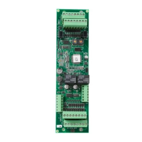
Rotary Address Switches - Set the board address for
each SIM-16 using both of the ten-position rotary
switches located on the board (See Figure 1). Each of
these addresses must be a sub-address of the NIC-C
or the DAC-NET (in CE applications) and must be the same as the addresses
assigned in the Zeus Programming Tool.
TB1
1
2
9
10
P2
TB3
6
1
TB2
Figure 1
SIM-16 Supervised Input
Module
Siemens Building Technologies
SIM-16
3
4
5
6
7
8
11
12
13
14
15
16
P3
S1
S2
TB4
6
1
Fire Safety
Advertisement
Table of Contents

Subscribe to Our Youtube Channel
Related Manuals for Siemens SIM-16


Summary of Contents for Siemens SIM-16
- Page 1 The relays and the input s are programmable using the Zeus Programming Tool. OPERATION The SIM-16 is mounted in an enclosure that is remotely located from the Main Panel. Communication between the SIM-16 and the NIC-C (Network Interface Card) or the next CAN module (in CE applications) is through the Control Area Network (CAN) bus.
- Page 2 • Each SIM-16 module is a node in the CAN bus. • The SIM-16 can be inst alled with or without an RNI. Connect the CAN bus and 24V as shown in Figures 2 and 3. • Up to 99 CAN modules, in any combination, can be connected to the CAN bus of each NIC-C or the CAN bus of the DAC-NET (in CE applications).
- Page 3 Figure 2 SIM-16 CAN Bus Connections With An RNI NOTES 1. All wiring supervised. All wiring power limited to NFPA 70 per NEC 760. 3. Wiring for TB1 and TB2 is 18 AWG (1.0mm ) min., 12 AWG (4mm ) max.
- Page 4 12 AWG (4mm ) max. 5. Wiring for TB3 and TB4 is 26 AWG (∅ 0.25mm) min., 16 AWG (1.5mm ) max. Figure 4 SIM-16 Relay Connections ELECTRICAL RATINGS i t c i t c Siemens Building Technologies P/N 315-034060-3 Fire Safety...
- Page 5 THE SIM-16 18 AWG (1.0mm ) min., 12 AWG (4mm ) max. 4. Maximum distance 500 feet (165m) from SIM-16 to supervised input. 5. In the Zeus Programming Tool, select supervised for each supervised input. 6. Supervised and unsuper- INPUT #6...
- Page 6 For CE applications in Cerberus E100 systems refer to Installation Instruction A24205-A334-B844 (English) or A24205-A334-A844 (German). Siemens Building Technologies, Inc. Siemens Building Technologies, Ltd. Siemens AG 8 Fernwood Road 2 Kenview Boulevard I BT DE FS SYS Florham Park, New Jersey 07932 Brampton, Ontario L6T 5E4 CN D-81379 München...
Need help?
Do you have a question about the SIM-16 and is the answer not in the manual?
Questions and answers