Siemens Simatic series Manual

Siemens Simatic series Manual

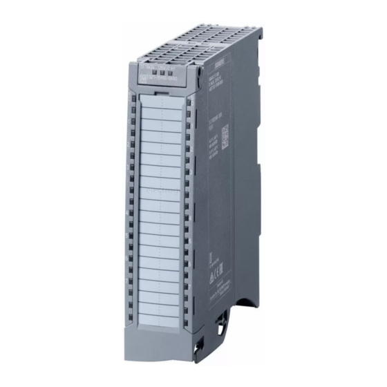
Digital input module for siemens simatic s7-1500; siemens simatic et 200mp
Hide thumbs Also See for Simatic series:

Advertisement

Advertisement

Table of Contents
loading

Summary of Contents for Siemens Simatic series

  • Page 2 ___________________ Preface ___________________ Documentation guide ___________________ SIMATIC Product overview ___________________ Wiring S7-1500/ET 200MP DI 16x24VDC HF ___________________ Digital Input Module Parameters/address space (6ES7521-1BH00-0AB0) ___________________ Interrupts/diagnostics alarms Manual ___________________ Technical specifications ___________________ Dimensional drawing ___________________ Parameter data records 08/2018 A5E03485952-AG...
  • Page 3 Note the following: WARNING Siemens products may only be used for the applications described in the catalog and in the relevant technical documentation. If products and components from other manufacturers are used, these must be recommended or approved by Siemens. Proper transport, storage, installation, assembly, commissioning, operation and maintenance are required to ensure that the products operate safely and without any problems.
  • Page 4: Preface

    Purpose of the documentation This manual supplements the S7-1500/ET 200MP (https://support.industry.siemens.com/cs/ww/en/view/59191792) system manual. Functions that relate in general to the systems are described in this system manual. The information provided in this manual and in the system/function manuals supports you in commissioning the systems.
  • Page 5 Siemens' products and solutions undergo continuous development to make them more secure. Siemens strongly recommends that product updates are applied as soon as they are available and that the latest product versions are used. Use of product versions that are no longer supported, and failure to apply the latest updates may increase customers' exposure to cyber threats.
  • Page 6: Table Of Contents

    Table of contents Preface ..............................3 Documentation guide ..........................6 Product overview ..........................10 Properties ..........................10 Functions ..........................13 2.2.1 Count............................13 Wiring ..............................14 Parameters/address space ........................16 Parameter ..........................16 4.1.1 Parameters ..........................16 4.1.2 Parameters DI mode ....................... 17 4.1.3 Explanation of the parameters of the DI mode ...............
  • Page 7: Documentation Guide

    S7-1500 and ET 200MP systems, e.g. diagnostics, communication, motion control, Web server, OPC UA. You can download the documentation free of charge from the Internet (https://support.industry.siemens.com/cs/ww/en/view/109742691). Changes and supplements to the manuals are documented in a Product Information. You can download the product information free of charge from the Internet (https://support.industry.siemens.com/cs/us/en/view/68052815).
  • Page 8 You must register once to use the full functionality of "mySupport". You can find "mySupport" on the Internet (https://support.industry.siemens.com/My/ww/en). "mySupport" - Documentation In the Documentation area in "mySupport" you can combine entire manuals or only parts of these to your own manual.
  • Page 9 Solutions are shown in interplay with multiple components in the system - separated from the focus on individual products. You will find the application examples on the Internet (https://support.industry.siemens.com/sc/ww/en/sc/2054). TIA Selection Tool With the TIA Selection Tool, you can select, configure and order devices for Totally Integrated Automation (TIA).
  • Page 10 You can find SIEMENS PRONETA on the Internet (https://support.industry.siemens.com/cs/ww/en/view/67460624). SINETPLAN SINETPLAN, the Siemens Network Planner, supports you in planning automation systems and networks based on PROFINET. The tool facilitates professional and predictive dimensioning of your PROFINET installation as early as in the planning stage. In addition, SINETPLAN supports you during network optimization and helps you to exploit network resources optimally and to plan reserves.
  • Page 11: Product Overview

    Product overview Properties Article number: 6ES7521-1BH00-0AB0 View of the module Figure 2-1 View of the DI 16x24VDC HF module Properties The module has the following technical properties: ● 16 digital inputs; electrically isolated in groups of 16 – of which channel 0 and 1 optionally with counter function ●...
  • Page 12 Product overview 2.1 Properties The module supports the following functions: Table 2- 1 Version dependencies of the module functions Configuration software Function Firmware version STEP 7 GSD file in STEP 7 of the module (TIA Portal) (TIA Portal) V12 or higher, or STEP 7 V5.5 SP3 or higher Firmware update V1.0.0 or higher...
  • Page 13 Other components The following component must be ordered separately: Front connectors, including potential jumpers and cable ties For more information on accessories, refer to the system manual S7-1500/ET 200MP (http://support.automation.siemens.com/WW/view/en/59191792). DI 16x24VDC HF Digital Input Module (6ES7521-1BH00-0AB0) Manual, 08/2018, A5E03485952-AG...
  • Page 14: Functions

    You will find the basics and additional information on the counting function in the function manual Counting, measuring and position detection (http://support.automation.siemens.com/WW/view/en/59709820). Counting with channel 0 and channel 1 You control the counting function via the IO addresses of the module. These IO addresses are also known as the control interface (output addresses) and feedback interface (input addresses), see section AUTOHOTSPOT.
  • Page 15: Wiring

    You can find information on wiring the front connector, creating a cable shield, etc. in the Wiring section of the S7-1500/ET 200MP (http://support.automation.siemens.com/WW/view/en/59191792) system manual. Wiring and block diagram The figure below shows you how to wire the module and the assignment of the channels to the addresses (input byte a to input byte b).
  • Page 16 Wiring Resistor circuitry of the encoders To detect a wire break, it is necessary that enough quiescent current is flowing even when the encoder contacts are open. Connect a resistor of 25 kΩ to 45 kΩ with 0.25 W to the encoder contacts for this reason.
  • Page 17: Parameters/Address Space

    Parameters/address space Parameter 4.1.1 Parameters DI 16x24VDC HF parameters When you assign the module parameters in STEP 7, you use various parameters to specify the module properties. The parameters that can be set depend on whether you use the module in standard mode or in counter mode. You will find the parameters in section Parameters DI mode (Page 17) or section Parameters of the Counting mode (Page 19).
  • Page 18: Parameters Di Mode

    Parameters/address space 4.1 Parameter 4.1.2 Parameters DI mode Parameters of the DI 16x24VDC HF in the DI mode In the table below you will find the parameters in the DI mode. These parameters apply to channels 0 to 15. Table 4- 1 Settable parameters and their defaults in the DI mode Parameter Range of values...
  • Page 19: Explanation Of The Parameters Of The Di Mode

    Parameters/address space 4.1 Parameter 4.1.3 Explanation of the parameters of the DI mode No supply voltage L+ Enabling of the diagnostics, with missing or too little supply voltage L+. Wire break Enabling diagnostics if the line to the encoder is interrupted. Input delay This parameter can be used to suppress signal disruptions.
  • Page 20: Parameters Of The Counting Mode

    Parameters/address space 4.1 Parameter 4.1.4 Parameters of the Counting mode Parameters of the DI 16x24VDC HF Count in the Counting mode If you want to use the module for counting, you need to set the module parameters as DI 16x24VDC HF Count. For channels 0 and channel 1, the following parameter settings are then possible.
  • Page 21: Explanation Of The Parameters Of The Counting Mode

    Parameters/address space 4.1 Parameter Parameter Range of values Default Parameter Range of effectiveness with con- setting reassignment figuration software, e.g. STEP 7 in RUN Integrated in the GSD file hardware catalog PROFIBUS DP as of STEP 7, V13 SP1 with HSP 0118 or GSD file PROFINET IO...
  • Page 22 Parameters/address space 4.1 Parameter Set output DQ With this parameter, you specify the behavior of the STS_DQ bit in the feedback interface. You can assign this bit in the user program, for example, with a hardware output, see AUTOHOTSPOT. Behavior Meaning Between a STS_DQ bit is set if the following condition is met:...
  • Page 23: Address Space

    Parameters/address space 4.2 Address space Address space The module can be configured differently in STEP 7; see following table. Depending on the configuration, additional/different addresses are assigned in the process image of the inputs. The letters "a to b" are printed onto the module. "EB a" for example, stands for module start address input byte a.
  • Page 24: Address Space Di Mode

    Parameters/address space 4.2 Address space 4.2.1 Address space DI mode Address space for configuration as 16-channel DI 16x24VDC HF QI The figure below shows the assignment of the address space for the configuration as a 16-channel module with value status. You can freely assign the start address for the module. The addresses of the channels are derived from the start address.
  • Page 25 Parameters/address space 4.2 Address space Address space for configuration as 1 x 16-channel DI 16x24VDC HF MSI The channels 0 to 15 of the module are copied in up to four submodules with configuration 1 x 16-channel module (Module-internal shared input, MSI). Channels 0 to 15 are then available with identical input values in different submodules.
  • Page 26: Address Space Counting Mode

    You can find information on the module-internal shared input/shared output (MSI/MSO) function in the section Module-internal shared input/shared output (MSI/MSO) of the function manual PROFINET with STEP 7 V13 (http://support.automation.siemens.com/WW/view/en/49948856). 4.2.2 Address space Counting mode Address space for configuration as 1 x 16-channel DI 16x24VDC Count The address space of channel 0 and channel 1 used for counting consists of the control and feedback interface.
  • Page 27 Parameters/address space 4.2 Address space Control interface The figure below shows the address assignment of the module in the process image output. You use the control interface, for example, to start the counter or to set the counter value. With the "SW gate" control bit you open and close the software gate of the corresponding channel.
  • Page 28 Parameters/address space 4.2 Address space Figure 4-6 Assignment of the address space of the control interface of the DI 16x24VDC Count (bytes 8 to 15) DI 16x24VDC HF Digital Input Module (6ES7521-1BH00-0AB0) Manual, 08/2018, A5E03485952-AG...
  • Page 29 Parameters/address space 4.2 Address space Feedback interface The figure below shows the address assignment of the module in the process image input. The feedback interface for the counters (channels 0 and 1) begins at input byte x+4. Via the feedback interface, the user program receives current counted values and status information from the module.
  • Page 30 Parameters/address space 4.2 Address space Figure 4-8 Assignment of the address space of the feedback interface of the DI 16x24VDC Count (bytes 12 to 19) DI 16x24VDC HF Digital Input Module (6ES7521-1BH00-0AB0) Manual, 08/2018, A5E03485952-AG...
  • Page 31: Examples Of Counting

    Parameters/address space 4.2 Address space 4.2.3 Examples of counting In this section, you will find examples of the behavior of the counter and how you can specify this behavior. You specify the properties of the counter in the parameter assignment. Behavior when a counting limit is exceeded - Stop counting The following section describes the effects of the parameter "Behavior when a counting limit is exceeded = Stop counting".
  • Page 32 Parameters/address space 4.2 Address space Behavior when a counting limit is exceeded - Continue counting The following section describes the effects of the parameter "Behavior when a counting limit is exceeded = Continue counting". To control the counter, the bits of the control byte of the control interface are used, see section Address space Counting mode (Page 25), subsection Control interface.
  • Page 33 Parameters/address space 4.2 Address space Set output DQ - behavior of the STS_DQ bit The following section shows the behavior of the STS_DQ bit with the parameter assignment "Set output DQ = between comparison value and high counting limit". The STS_DQ bit is set to 1 when the comparison value <...
  • Page 34 The software gate is controlled by the user program. Reference You can find additional information on the counting functionality in the function manual S7- 1500, ET 200MP, ET 200SP counting, measuring and position detection (http://support.automation.siemens.com/WW/view/en/59709820). DI 16x24VDC HF Digital Input Module (6ES7521-1BH00-0AB0) Manual, 08/2018, A5E03485952-AG...
  • Page 35: Interrupts/Diagnostics Alarms

    Interrupts/diagnostics alarms Status and error displays LED displays The following figure shows the LED displays (status and error displays) of DI 16x24VDC HF. Figure 5-1 LED displays of the DI 16x24VDC HF module DI 16x24VDC HF Digital Input Module (6ES7521-1BH00-0AB0) Manual, 08/2018, A5E03485952-AG...
  • Page 36 Interrupts/diagnostics alarms 5.1 Status and error displays Meaning of the LED displays The following tables explain the meaning of the status and error displays. Remedial measures for diagnostic reports can be found in chapter Diagnostics alarms (Page 38). RUN and ERROR LED Table 5- 1 Status and error displays RUN and ERROR Meaning...
  • Page 37: Interrupts

    Interrupts/diagnostics alarms 5.2 Interrupts Interrupts Digital input module DI 16x24VDC HF supports diagnostic and hardware interrupts. You can find detailed information on the error event in the error organization block with the "RALRM" instruction (read additional interrupt info) and in the STEP 7 online help. Diagnostics interrupt The module generates a diagnostic interrupt at the following events: ●...
  • Page 38 Interrupts/diagnostics alarms 5.2 Interrupts Structure of the additional interrupt information Table 5- 4 Structure of USI = W#16#0001 Data block name Contents Comment Bytes W#16#0001 Additional interrupt info for hardware interrupts of the I/O module (User Structure Identifier) The channel that triggered the hardware interrupt follows. Channel B#16#00 to B#16#0F Number of the event-triggering channel (chan-...
  • Page 39: Diagnostics Alarms

    Interrupts/diagnostics alarms 5.3 Diagnostics alarms Diagnostics alarms Diagnostics alarms A diagnostics alarm is output for each diagnostics event and the ERROR LED flashes on the module. The diagnostics alarms can, for example, be read from the diagnostics buffer of the CPU.
  • Page 40: Technical Specifications

    Technical specifications Technical specifications of the DI 16x24VDC HF The following table shows the technical specifications as of 08/2018. You will find a data sheet including daily updated technical specifications on the Internet (https://support.industry.siemens.com/cs/ww/en/pv/6ES7521-1BH00-0AB0/td?dl=en). Article number 6ES7521-1BH00-0AB0 General information Product type designation...
  • Page 41 Technical specifications Article number 6ES7521-1BH00-0AB0 Power loss Power loss, typ. 2.6 W Digital inputs Number of digital inputs Digital inputs, parameterizable Source/sink input P-reading Input characteristic curve in accordance with IEC 61131, type 3 Digital input functions, parameterizable Gate start/stop •...
  • Page 42 Technical specifications Article number 6ES7521-1BH00-0AB0 Encoder Connectable encoders 2-wire sensor • 1.5 mA – permissible quiescent current (2-wire sensor), max. Isochronous mode Isochronous operation (application synchro- nized up to terminal) Filtering and processing time (TCI), min. 80 µs; At 50 μs filter time Bus cycle time (TDP), min.
  • Page 43 Technical specifications Article number 6ES7521-1BH00-0AB0 Ambient conditions Ambient temperature during operation 0 °C horizontal installation, min. • 60 °C horizontal installation, max. • 0 °C vertical installation, min. • 40 °C vertical installation, max. • Decentralized operation Prioritized startup Dimensions Width 35 mm Height...
  • Page 44: Dimensional Drawing

    Dimensional drawing The dimensional drawing of the module on the mounting rail, as well as a dimensional drawing with open front cover, are provided in the appendix. Always observe the specified dimensions for installation in cabinets, control rooms, etc. Figure A-1 Dimensional drawing of the DI 16x24VDC HF module DI 16x24VDC HF Digital Input Module (6ES7521-1BH00-0AB0) Manual, 08/2018, A5E03485952-AG...
  • Page 45 Dimensional drawing Figure A-2 Dimensional drawing of the DI 16x24VDC HF module, side view with open front cover DI 16x24VDC HF Digital Input Module (6ES7521-1BH00-0AB0) Manual, 08/2018, A5E03485952-AG...
  • Page 46: Parameter Data Records

    Parameter data records Parameter assignment and structure of the parameter data records The data records of the module have an identical structure, regardless of whether you configure the module with PROFIBUS DP or PROFINET IO. Dependencies for configuration with GSD file When configuring the module with a GSD file, remember that the settings of some parameters are dependent on each other.
  • Page 47 0 and 1 are not read back. You get the diagnostics data records 0 and 1 for the read back parameter data records 0 and 1. You can find more information in the Interrupts section of the PROFIBUS DP interface module device manual on the Internet (http://support.automation.siemens.com/WW/view/en/78324181). DI 16x24VDC HF Digital Input Module (6ES7521-1BH00-0AB0) Manual, 08/2018, A5E03485952-AG...
  • Page 48: Structure Of The Parameter Data Records Di Mode

    Parameter data records B.2 Structure of the parameter data records DI mode Structure of the parameter data records DI mode Assignment of data record and channel For the configuration with 1 x 16 channels, the parameters are located in data records 0 to 15 and are assigned as follows: ●...
  • Page 49 Parameter data records B.2 Structure of the parameter data records DI mode Structure of a data record in the DI mode The example in the figure below shows the structure of data record 0 for channel 0. The structure of channels 1 to 15 is identical. The values in byte 0 and byte 1 are fixed and may not be changed.
  • Page 50: Structure Of The Parameter Data Records Counting Mode

    Parameter data records B.3 Structure of the parameter data records Counting mode Structure of the parameter data records Counting mode Assignment of data record and channel For the configuration with 1 x 16 channels, the parameters are located in data records 0 to 15 and are assigned as follows: ●...
  • Page 51 Parameter data records B.3 Structure of the parameter data records Counting mode Structure of data record 0 of the Counting mode The example in the figure below shows the structure of data record 0 for channel 0. The structure of channel 1 is identical, the values are located in data record 1. The values in byte 0 and byte 1 are fixed and may not be changed.
  • Page 52 Parameter data records B.3 Structure of the parameter data records Counting mode Figure B-3 Structure of data record 0: Bytes 5 to 17 Keep in mind that the counter is stopped and reset to the start value when you change count parameters.

This manual is also suitable for:

Di 16x24vdc hf6es7521-1bh00-0ab0

Table of Contents