
Related Manuals for MasterCraft 055-6755-8


Summary of Contents for MasterCraft 055-6755-8
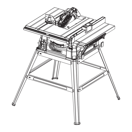
- Page 1 055-6755-8 TABLE SAW WITH HEAVY-DUTY STEEL STAND IMPORTANT: INSTRUCTION Please read this manual carefully before using this table MANUAL saw and save it for reference.
- Page 2 055-6755-8 | contact us 1-800-689-9928 TABLE OF CONTENTS Quick Start Guide Specifications Safety Guidelines Know Your Table Saw Assembly Instructions Operating Instructions Maintenance Troubleshooting Exploded View Parts List Warranty NOTE: If any parts are missing or damaged, or if you have any questions, please call our toll-free helpline at 1-800-689-9928.
- Page 3 055-6755-8 | contact us 1-800-689-9928 SPECIFICATIONS • Place the table saw on top of the stand, aliging the holes in the base with the holes in the Motor 120 V AC, 60 Hz, 15A stand. Speed 4700/MIN (no load) •...
- Page 4 055-6755-8 | contact us 1-800-689-9928 SAFETY GUIDELINES 2) Electrical safety Power tool plugs must match the outlet. Never modify the plug in any way. Do not use any • This manual contains information that relates to PROTECTING PERSONAL SAFETY and PREVENTING adaptor plugs with earthed (grounded) power tools.
- Page 5 055-6755-8 | contact us 1-800-689-9928 WARNING! Do not use the power tool if the switch does not turn it on and off. Any power tool that cannot • Do not operate the saw without the proper blade guard in place for all through cut operations. Make be controlled with the switch is dangerous and must be repaired.
- Page 6 055-6755-8 | contact us 1-800-689-9928 Do not abuse cord. Never yank cord to disconnect from receptacle. Keep cord away from heat, oil, and workpiece can cause kickback or stall the motor. • sharp edges. • Use the right tool. Don’t force the tool or attachment to do a job it was not designed for. Don’t use it for a purpose not intended.
- Page 7 055-6755-8 | contact us 1-800-689-9928 Keep tool dry, clean, and free from oil and grease. Always use a clean cloth when cleaning. Never Make sure the saw blade is not contacting the guard, riving knife or the workpiece before •...
- Page 8 055-6755-8 | contact us 1-800-689-9928 Feed workpiece at an even pace. Do not bend or twist the workpiece. If jamming occurs, turn the tool Keep saw blades clean, sharp, and with sufficient set. Never use warped saw blades or saw •...
- Page 9 055-6755-8 | contact us 1-800-689-9928 Use an auxiliary fence in contact with the table top when ripping workpieces less than 1/16" • 3. Keeping spreader, anti-kickback pawls, and blade guard in place and operating. (2 mm) thick. A thin workpiece may wedge under the rip fence and create a kickback. Support large 4.
- Page 10 055-6755-8 | contact us 1-800-689-9928 The table below shows the correct size to use, depending on the cord length and nameplate amperage rating. DOUBLE INSULATION If in doubt, use the next heavier gauge. The smaller the gauge number, the heavier the cord.
- Page 11 055-6755-8 | contact us 1-800-689-9928 Description Description Blade guard Plug cable Riving knife Dust extraction port Anti-kickback pawls Blade guard storage Right extension table Table insert Sub fence Rip fence Rip fence storage Saw blade Push stick Bevel scale...
- Page 12 055-6755-8 | contact us 1-800-689-9928 Blade guard: Right extension table: The guard is installed over the riving knife. It protects the operator’s hand from being cut while providing a The extension table is a separate part that is located on the right side of the work table to provide additional clear view of the material to be cut during through-sawing cuts.
- Page 13 055-6755-8 | contact us 1-800-689-9928 Avoiding kickback: PACKAGE CONTENTS • Always use the correct blade depth setting. The top of the blade teeth should clear the workpiece by FOR TABLE SAW 1/8 - 1/4" (3.2 - 6.4 mm).
- Page 14 055-6755-8 | contact us 1-800-689-9928 Description Qty. Illustration Description Qty. Illustration Hex bolts M6 x 12 with spring washers 6 Height/bevel adjusting handwheel and flat washers 6 Nuts M6 Hex bolts M6 x 25 with nuts M6 and Rip fence storage big flat washers 6...
- Page 15 055-6755-8 | contact us 1-800-689-9928 MOUNTING HOLES Description Qty. Illustration The table saw must be mounted to a firm supporting surface such as a workbench or leg stand. Four bolt Screw M6 x 12 with flat washers 6, holes have been provided in the saw’s frame for this purpose.
- Page 16 055-6755-8 | contact us 1-800-689-9928 • Attach one end of the short top leg bracket stamped D • Attach one long bottom leg bracket stamped C (9) to (10) to the rear frame assembly using a screw M6 x12 the centre of each stand leg (2) using a screw M6 x12 (3), flat washer 6 (4), spring washer 6 (5) and hex nut...
- Page 17 055-6755-8 | contact us 1-800-689-9928 • Insert the rubber foot (12) into the bottom of each • Attach one end of the short bottom leg bracket stand leg (2). stamped E (11) to the rear frame assembly using one •...
- Page 18 055-6755-8 | contact us 1-800-689-9928 INSTALL THE HEIGHT/BEVEL ADJUSTING RIVING KNIFE INSTALLATION AND POSITION HANDWHEEL (Fig. 4) (Fig. 7a-7b) • Attach the height/bevel adjusting handwheel (1) into • Turn saw off and unplug saw. the fix pole (2) and align the hole on the height/bevel adjusting handwheel with the hole on the fix pole.
- Page 19 055-6755-8 | contact us 1-800-689-9928 INSTALL THE RIGHT EXTENSION TABLE REMOVE AND INSTALL THE BLADE (Fig. 10) (Fig. 8) CAUTION: • Align the holes on the right extension table (1) with the To work properly, the saw blade teeth must point down toward the front of the saw. Failure to heed holes on the work table.
- Page 20 055-6755-8 | contact us 1-800-689-9928 BLADE GUARD INSTALLATION (Fig. 13a-13b) CAUTION! Ensure the large, flat surface (cupped side of the outer blade flange) of the outer flange faces the • Turn saw off and unplug saw. saw blade and the saw blade (5) is firmly seated against the inner blade flange (7).
- Page 21 055-6755-8 | contact us 1-800-689-9928 RIP FENCE INSTALLATION AND USE CHECK THE ALIGNMENT OF THE RIP FENCE (Fig. 14a-14b) TO THE BLADE (Fig. 15) INSTALLATION: • Unplug the saw. • Remove the blade guard assembly and anti-kickback •...
- Page 22 055-6755-8 | contact us 1-800-689-9928 MITRE GAUGE INSTALLATION AND USE CHANGE BLADE ANGLE (BEVEL) (Fig. 19) (Fig. 17a-17b) • Loosen the bevel locking lever (1) counter-clockwise. • Adjust bevel angle by first pushing height/bevel INSTALLATION: adjusting handwheel (2) all the way to the left.
- Page 23 055-6755-8 | contact us 1-800-689-9928 • Raise the blade to the maximum height by turning the INSTALL BLADE GUARD STORAGE (Fig. 22) height-adjusting knob clockwise. • Align the holes in the blade guard storage (1 & 2) with •...
- Page 24 055-6755-8 | contact us 1-800-689-9928 CONNECT TO A DUST COLLECTION SYSTEM WARNING! (Fig. 26) To reduce the risk of serious personal injury, turn unit off and unplug the tool before making any adjustments or removing/installing attachments or accessories. An accidental start-up can cause The dust extraction port (1) with a 1 7/8"...
- Page 25 055-6755-8 | contact us 1-800-689-9928 AVOIDING KICKBACK WARNING! Never operate the saw with the blade guard removed except for non-through cuts. Reinstall the Kickback can be avoided by taking following proper precautions: blade guard immediately after finishing any non-through cut operations which require removal of •...
- Page 26 055-6755-8 | contact us 1-800-689-9928 HOW TO MAKE AN ADDITIONAL PUSH STICK ON/OFF SWITCH AND OVERLOAD RESET Included standard push stick (Fig. 29a-29b) BUTTON (Fig. 28) • The product can be switched on by pressing the • In order to operate your table saw safely, you must green “I”-Button on the on/off switch (1).
- Page 27 055-6755-8 | contact us 1-800-689-9928 AUXILIARY FENCE Featherboards A featherboard is a device used to help control the workpiece by guiding it securely against the table or rip An auxiliary fence is a device used to close the gap between rip fence and working table. ALWAYS make and fence.
- Page 28 055-6755-8 | contact us 1-800-689-9928 WARNING! • The blade provided with the saw is a high-quality combination blade suitable for ripping and cross cut DO NOT attempt to make any cuts not covered here. operations. Carefully check all setups and rotate the blade one full revolution to assure proper clearance before connecting saw to power source.
- Page 29 055-6755-8 | contact us 1-800-689-9928 MAKING A RIP CUT Cross cuts are straight 90° cuts made across the grain of the workpiece. The wood is fed into the cut at a 90° angle to the blade, and the blade is vertical.
- Page 30 055-6755-8 | contact us 1-800-689-9928 MAKING A BEVEL CROSS CUT • Set blade to correct depth for workpiece. • Position the rip fence the desired distance from the blade for the cut and securely lock the handle. WARNING! •...
- Page 31 055-6755-8 | contact us 1-800-689-9928 MAKING A NON-THROUGH CUT • Set the blade to the correct depth for the workpiece. • Depending on the shape and size of the wood, use either the rip fence or mitre gauge.
- Page 32 055-6755-8 | contact us 1-800-689-9928 TROUBLESHOOTING WARNING! When servicing, use only identical replacement parts. Use of any other part may create a hazard or cause product damage. Problem Possible Causes Solution Saw will not start. • Overload tripped.
- Page 33 055-6755-8 | contact us 1-800-689-9928 Problem Possible Causes Solution Material kicked back from • Rip fence out of adjustment. • Align rip fence with mitre gauge blade. slot. • Riving knife not aligned with blade. • Align riving knife with blade.
- Page 34 055-6755-8 | contact us 1-800-689-9928...
- Page 35 055-6755-8 | contact us 1-800-689-9928...
- Page 36 055-6755-8 | contact us 1-800-689-9928 PARTS LIST Description Qty. Description Qty. Screw ST4.2 x 12 Screw M8 x 30 Description Qty. Description Qty. Blade guard storage (A) Blade guard storage (B) Shaft retaining ring Scale label Cabinet Anti-kickback pawls storage...
- Page 37 3-Year Limited Warranty Description Qty. Description Qty. This Mastercraft product is guaranteed for a period of 3 years from the date of original retail purchase against Cylindrical pin Positioning plate defects in workmanship and materials, except for the following component: Cam platen...
Need help?
Do you have a question about the 055-6755-8 and is the answer not in the manual?
Questions and answers
I need on /off switch for table saw it stopped working?