
Related Manuals for MasterCraft 055-6748-6


Summary of Contents for MasterCraft 055-6748-6
-
Page 1: Extension Table
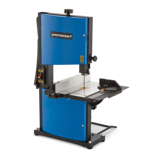
055-6748-6 BAND SAW WITH EXTENSION TABLE IMPORTANT: INSTRUCTION Please read this manual carefully before running this band saw MANUAL and save it for reference. - Page 2 TABLE OF CONTENTS Quick Start Guide Specifications Safety Guidelines 6-10 Know Your Band Saw 11-15 Assembly Instructions 16-26 Operating Instructions 27-29 Maintenance Troubleshooting 31-33 Exploded View 34-35 Parts List 36-38 Warranty NOTE: If any parts are missing or damaged, or if you have any questions, please call our toll-free helpline at 1-800-689-9928 SAVE THESE INSTRUCTIONS This manual contains important safety and operating instructions.
-
Page 3: Specifications
055-6748-6 | contact us 1-800-689-9928 SPECIFICATIONS • Holding the work table with your left hand while pulling the table, tilt Motor 120 V, 60 Hz, 2.5A adjustment knob (6) away from the saw Motor speed 2556 SFM (no load) -
Page 4: Safety Guidelines
055-6748-6 | contact us 1-800-689-9928 SAFETY GUIDELINES • WEAR A FACE MASK OR DUST MASK. Sawing operations produce dust. Dust generated from certain materials can be hazardous to your health. Always operate the band saw in This manual contains information that relates to PROTECTING PERSONAL SAFETY and PREVENTING a well-ventilated area, and provide for proper dust removal. -
Page 5: Safety Guidelines
055-6748-6 | contact us 1-800-689-9928 ELECTRICAL SAFETY • USE EXTRA SUPPORTS to prevent workpieces from sliding off the tabletop. Never use another person in place of a table extension, or to provide additional support for the workpiece. GUIDELINES FOR USING EXTENSION CORDS: •... - Page 6 055-6748-6 | contact us 1-800-689-9928 • Use a separate electrical circuit for your tools. This circuit must consist of not less than #12 wire with a 20 A time-delayed fuse or a #14 wire with a 15 A time-delayed fuse. Before connecting the motor to the power line, make sure the switch is in the Off position and the electric current is rated the same as the current stamped on the motor nameplate.
- Page 7 055-6748-6 | contact us 1-800-689-9928 Table tilt locking knob: Description Description Loosening the table tilt locking knob allows the work table to be tilted at different angles. Tightening the table Blade tension knob Extension table tilt locking knob locks the work table in place.
- Page 8 055-6748-6 | contact us 1-800-689-9928 Drive belt: • Cutting with a dull, gummed-up or improperly set blade The drive belt is fitted onto the lower drive wheel. The belt must be properly tensioned to enable smooth Avoiding kickback: operation of the drive wheel.
- Page 9 055-6748-6 | contact us 1-800-689-9928 PACKAGE CONTENTS Description Qty. Illustration Description Illustration M6 Flat washers Band saw assembly M5 Flat washers Mitre gauge M5 Hex nuts Rip fence M6x30 Hex bolts Additional support M5x20 Hex bolts Work table assembly...
- Page 10 055-6748-6 | contact us 1-800-689-9928 TOOLS NEEDED FOR ASSEMBLY MOUNTING RUBBER FEET ON THE BASE (Fig. 2) • Insert the four rubber feet (1) into holes provided in the four corners of saw base. Star-head screwdriver Framing square •...
- Page 11 055-6748-6 | contact us 1-800-689-9928 ASSEMBLING THE WORK TABLE (Fig. 5-7) If lag bolts are used, make sure they are long enough to go through holes in the saw base and material the saw is being • Remove the D-nut (1), flat washer (2) and wing screw mounted to.
- Page 12 055-6748-6 | contact us 1-800-689-9928 WORK TABLE TILT ADJUSTMENT (Fig. 10) SQUARING THE SAW TABLE TO THE BLADE (Fig. 8-9) Before adjusting the band saw, turn Off the band saw, • Turn the blade tracking knob (1) counter-clockwise to remove the safety key, and unplug the power cord from the unlock the blade guide assembly (2).
- Page 13 055-6748-6 | contact us 1-800-689-9928 TRACKING THE BLADE (Fig. 16-17) REMOVING AND INSTALLING THE BLADE (Fig. 13-15) • Disconnect the band saw from power source. • Loosen and remove the D-nut, flat washer and wing screw from the work table (1).
- Page 14 055-6748-6 | contact us 1-800-689-9928 ON/OFF SWITCH ASSEMBLY (Fig. 21) TRACKING THE BLADE (Fig. 18-19) • Insert switch key (1) into switch (2), and move the • Loosen the screws (1) to adjust guide pins (2) provided switch to the On position to turn On the band saw.
- Page 15 055-6748-6 | contact us 1-800-689-9928 CONTOUR CUTTING (Fig. 25-26) USING THE EXTENSION TABLE (Fig. 22) • Adjust the upper blade guide (1) using the upper guide When cutting a wider workpiece, you can use the extension. knob (2) so that the upper blade guide is positioned at The maximum extension table range is 2 5/32"...
- Page 16 055-6748-6 | contact us 1-800-689-9928 GENERAL MAINTENANCE TROUBLESHOOTING Avoid using solvents when cleaning plastic parts. Most plastics are susceptible to damage from various types PROBLEM Possible Causes Solution of commercial solvents. Use a clean cloth to remove dirt, dust, oil, grease, etc.
-
Page 17: Assembly Instructions
055-6748-6 | contact us 1-800-689-9928 PROBLEM Possible Causes Solution PROBLEM Possible Causes Solution Crooked cuts. • Workpiece is not placed properly • Use miter gauge to adjust tilt of the Saw does not start. • Motor cord or wall cord is not •... - Page 18 055-6748-6 | contact us 1-800-689-9928...
- Page 19 055-6748-6 | contact us 1-800-689-9928 PARTS LIST Description Description Description Description Bolt Spring washer Bracket (B) Cord clip Lower bezel panel Split washer Lower fixed block Hinge Fixed pin Cap nut Fine adjusting knob Cross-shaped sunk bolt Fixed block Big flat washer...
-
Page 20: Operating Instructions
055-6748-6 | contact us 1-800-689-9928 3-Year Limited Warranty This Mastercraft product is guaranteed for a period of 3 years from the date of original retail purchase against Description Description defects in workmanship and materials, except for the following component:...
Need help?
Do you have a question about the 055-6748-6 and is the answer not in the manual?
Questions and answers
I have a very old 55-6725-0 band saw. I want to remove the bottom wheel so I can put on a new tire. How do I remove it?