
Related Manuals for MasterCraft MAXIMUM 055-6768-8


Summary of Contents for MasterCraft MAXIMUM 055-6768-8
- Page 1 Dual-beveling Sliding Compound Mitre Saw with Laser Line model no. 055-6768-8 IMPORTANT: INSTRUCTION Please read this manual carefully before using this MANUAL mitre saw and save it for reference...
- Page 2 model no. 055-6768-8 | contact us 1-800-689-9928...
- Page 3 TABLE OF CONTENTS QUICK START GUIDE SYMBOLS SPECIFICATIONS SAFETY GUIDELINES TOOLS NEEDED FOR ASSEMBLY KNOW YOUR SLIDING MITRE SAW GLOSSARY OF TERMS CARTON CONTENTS ASSEMBLY ADJUSTMENTS OPERATION MAINTENANCE TROUBLESHOOTING GUIDE REPLACEMENT PARTS WARRANTY NOTE: If any parts are missing or damaged, or if you have any questions, please call our toll-free helpline at 1-800-689-9928 SAVE THESE INSTRUCTIONS This manual contains important safety and...
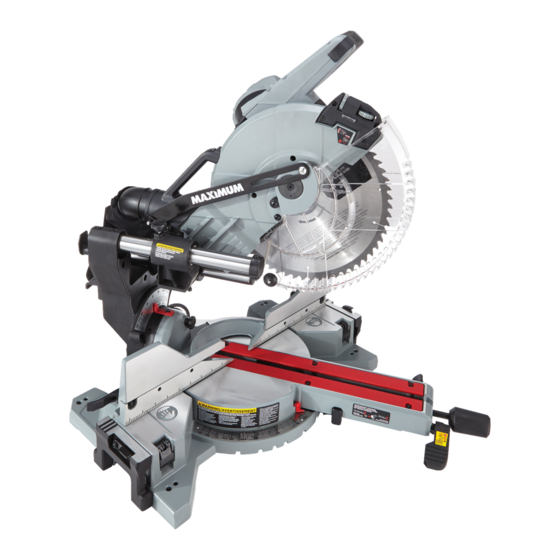
- Page 4 model no. 055-6768-8 | contact us 1-800-689-9928 Make sure all accessories and the blade Fig. A are installed correctly and are tight before operating the saw. NOTE: The blade has been installed in the mitre saw at the factory. Rechecking the blade before cutting is necessary.
- Page 5 Turn the laser guide on for pre-alignment of your Fig. D cut. Use the laser adjustment knobs to adjust the laser beam if necessary. Laser ON/OFF switch Laser assembly Place hands at least 22 cm (8 3/4") away from the Fig.
- Page 6 model no. 055-6768-8 | contact us 1-800-689-9928 WARNING ICONS Your power tool and its Owner’s Manual may contain “WARNING ICONS” (a picture symbol intended to alert you to and/or instruct you how to avoid a potentially hazardous condition). Understanding and heeding these symbols will help you operate your tool better and safer.
- Page 7 SPECIFICATIONS MOTOR POWER SOURCE 120V AC, 60 Hz, 15A SPEED 3200 RPM (No load) BRAKE ELECTRIC DOUBLE INSULATED ARBOUR SHAFT SIZE 5/8" (15.9 mm) BLADE DIAMETER 12" (30.5 cm), 60-tooth carbide-tipped ARBOUR SIZE 1" (25.4 mm) with a 5/8" (15.9 mm) reducer ROTATING TABLE MITRE ANGLE RANGE 0°–50°...
- Page 8 model no. 055-6768-8 | contact us 1-800-689-9928 GENERAL SAFETY RULES Safety is a combination of common sense, staying alert, and knowing how the mitre saw works. READ and become familiar with this Owner’s Manual. LEARN the tool’s • applications, limitations, and possible hazards. •...
- Page 9 • DO NOT LEAVE THE POWER SWITCH IN THE ON POSITION WHILE THE TOOL IS UNATTENDED. Turn the power switch to the OFF position. DO NOT leave the tool until it has come to a complete stop. • DO NOT STAND ON THE TOOL. Serious injury could result if the tool tips or is accidentally jarred.
- Page 10 model no. 055-6768-8 | contact us 1-800-689-9928 SPECIFIC SAFETY RULES FOR DUAL-BEVEL SLIDING MITRE SAW • USE ONLY CROSSCUTTING SAW BLADES. When using carbide-tipped blades, make sure they have a negative hook angle. Do not use blades with deep gullets, because they can deflect and contact the guard.
- Page 11 • MAKE SURE the blade is not contacting the workpiece before the switch is turned • NEVER unplug the saw with the switch in the ON position. • IMPORTANT: After completing the cut, release the power switch and wait for the blade to stop before returning the saw to the raised position.
- Page 12 model no. 055-6768-8 | contact us 1-800-689-9928 Replacement parts – When servicing, use only identical replacement parts. Polarized plugs – This saw has a plug that looks like the one shown on below: To reduce the risk of electric shock, this saw has a polarized plug (one blade is wider than the other).
- Page 13 • If the tool suddenly stalls while cutting wood, release the trigger switch, unplug the tool and free the blade from the wood. The saw may now be started and the cut finished. • FUSES may “blow” or circuit breakers may trip frequently if: a.
- Page 14 model no. 055-6768-8 | contact us 1-800-689-9928 MINIMUM GAUGE FOR EXTENSION CORDS (AWG) (when using 120V only) Amperage rating Total length of cord in feet More than Not more than 25’ (7.6 m) 50’ (15 m) 100’ (30 m) 150’ (45 m) Not Recommended CAUTION! In all cases make certain the receptacle in question is properly grounded.
- Page 15 SUPPLIED NOT SUPPLIED Blade wrench Adjustable wrench Star-head screwdriver 5 mm hex wrench Combination square Slotted screwdriver COMBINATION SQUARE MUST BE TRUE Should not gap or overlap when square is flipped over (see dotted figure). Draw light line on Straight edge or a 3/4 in. board, this board along this edge.
- Page 16 model no. 055-6768-8 | contact us 1-800-689-9928 Description Description Switch handle Left stop block Lower blade guard Left extension wing Mounting hole Left slide fence Quick cam mitre locking lever Hold-down clamp Mitre handle Slide carriage lock knob MItre detent override Carrying handle Positive mitre detents Safety lock...
- Page 17 Description Description Stop latch knob Positive stop locking lever Motor Bevel lock handle Right slide fence Table insert Right extension wing Extension wing lock knob Right stop block ON/OFF trigger switch Table Laser ON/OFF switch Blade...
- Page 18 model no. 055-6768-8 | contact us 1-800-689-9928 AMPERAGE (AMPS) – A measure of the flow of electric current. Higher ratings generally mean the tool is suited for heavier use. ARBOUR LOCK – Allows the user to keep the blade from rotating while tightening or loosening the arbour bolt during blade replacement or removal.
- Page 19 POSITIVE STOP LOCKING LEVER – Locks the mitre saw at a preset positive stop for the desired mitre angle. SWITCH HANDLE – The switch handle contains the trigger switch and safety lock-off button. The blade is lowered into the workpiece by pushing down on the handle. The saw will return to its upright position when the handle is released.
- Page 20 model no. 055-6768-8 | contact us 1-800-689-9928 UNPACKING Carefully remove the mitre saw from the carton. Separate the parts. Lay out all of the parts, and check them against the parts listed below. Examine all of the parts carefully. Description Mitre saw Mitre handle assembly Saw blade wrench...
- Page 21 ASSEMBLY INSTRUCTIONS CUTTING HEAD (Fig. 1) Fig. 1 Raising • Push down slightly on the switch handle (1). • Pull out the stop latch knob (2). • Allow the cutting head to rise to the up position. Locking When transporting or storing the mitre saw, the cutting head should always be locked in the down position.
- Page 22 model no. 055-6768-8 | contact us 1-800-689-9928 INSTALLING THE BEVEL LOCK HANDLE Fig. 3 (Fig. 3) • Insert the bevel lock handle (1) onto the shaft (2) at an approximately angle 30° below the level as shown in Fig. 3. •...
- Page 23 UNLOCKING THE SLIDE CARRIAGE Fig. 6 (Fig. 6) After removing the saw from the carton, loosen the slide carriage lock knob (1), located on the left side of the slide carriage. When transporting or storing the mitre saw, the slide carriage should always be locked in position.
- Page 24 model no. 055-6768-8 | contact us 1-800-689-9928 • Locate the arbour lock button (5) below the Fig. 8 trigger switch handle. (Fig. 8) • Press the arbour lock button (5), holding it in firmly while turning the blade wrench clockwise. This will engage the arbour lock allowing the arbour bolt to be loosened with the blade wrench.
- Page 25 • Rotate the cover plate (3) and lower blade guard (1) back to its original position. (Fig. 7) • Lower the blade guard and replace the cover plate screw (2) and tighten with a star-head screwdriver. (Fig 7) • Pull the main handle down and up several times to confirm the lower blade guard operates without binding.
- Page 26 model no. 055-6768-8 | contact us 1-800-689-9928 MOUNTING THE MITRE SAW (Fig. 11, 12) Mounting instructions: Fig. 11 • For stationary use, place the saw in the desired location, directly on a workbench 1. Mitre saw base where there is room for handling and 2.
- Page 27 • For portable use, place the saw on a 3/4" Fig. 12 thick piece of plywood. Bolt the base of the mitre saw securely to the plywood using the mounting holes on the base. Use C-clamps to clamp this mounting board to a stable work surface at the worksite.
- Page 28 model no. 055-6768-8 | contact us 1-800-689-9928 BEVEL STOP ADJUSTMENT Fig. 15 90° (0°) Bevel Adjustment (Fig. 15, 16) • Loosen bevel lock handle (1), and tilt the cutting arm completely to the right while pushing in the bevel detent pin (3 - Fig. 16) in against the 0°...
- Page 29 45° Right Bevel Positive Stop Adjustment Fig. 17 (Fig. 15, 16, 17) • Loosen the bevel lock handle (1) and set cutting arm at 45° angle. (Fig. 15) • Pull out the 33.9° detent pin (3) and tilt the cutting arm completely to the right. (Fig. 16) •...
- Page 30 model no. 055-6768-8 | contact us 1-800-689-9928 33.9° Right Bevel Adjustment (Fig. 18, 19) Fig. 18 • Set the mitre angle to 0°. Fully extend both sliding fences. • Loosen the bevel lock handle (1). (Fig. 18) • Tilt the cutting arm to the 33.9° right position stop by pushing in the 33.9°...
- Page 31 MITRE SCALE (Fig. 21) Fig. 21 The dual bevel slide mitre saw scale can be easily read, showing mitre angles from 0° to 50° to the left, and 0° to 50° to the right. The mitre saw table has positive stops at the most common angle settings: 0°, 15°, 22.5°, 31.6°, and 45°.
- Page 32 model no. 055-6768-8 | contact us 1-800-689-9928 ADJUSTING CUTTING DEPTH (Fig. 23, 24) Fig. 23 The maximum depth travel of the cutting head was set at the factory. Setting the maximum width travel of the cutting head. Follow the steps below (Fig. 23): •...
- Page 33 QUICK CAM MITRE LOCKING LEVER Fig. 25 ADJUSTMENT (Fig. 25) • Press down and lock the quick cam mitre locking lever (1). • If the table moves with the quick cam mitre locking lever in down position, turn the stop nut (2) to the left using a 13 mm wrench to extend the locking arm against the base of the mitre saw.
- Page 34 model no. 055-6768-8 | contact us 1-800-689-9928 AVOID DIRECT EYE CONTACT (Fig. 27) Fig. 27 Laser radiated when laser guide is turned on. Avoid direct eye contact. Laser Warning • Laser Warning Label: Label Max. Output < 5 mW Wavelength: 630−660 nm, Complies with 21 CFR 1040.10 and 1040.11.
- Page 35 LASER GUIDE ADJUSTMENT (Fig. 28, 29, 30, 31) NOTE: All the adjustments for the operation of this machine have been completed at the factory. Due to normal wear and use, some occasional readjustments may be necessary. A. Checking Laser Beam Alignment (Fig. 28) Fig.
- Page 36 model no. 055-6768-8 | contact us 1-800-689-9928 Procedure B (Fig. 29, 31) Fig. 30 • Slightly turn the laser horizontal adjustment knob (2) to adjust the horizontal angle of the laser beam on the top of the board. If the laser beam is out of parallel from left to right, turn the laser horizontal adjustment knob (2) clockwise;...
- Page 37 EXTENSION WING USE AND Fig. 32 ADJUSTMENT (Fig. 32) The left and right side extension wings can offer extra support for long workpieces. • Lift the locking lever (1) and pull out the left extension wing to the desired support length.
- Page 38 model no. 055-6768-8 | contact us 1-800-689-9928 SAFETY INSTRUCTIONS FOR BASIC SAW OPERATION BEFORE EACH USE Inspect your saw. • Disconnect the mitre saw. To avoid injury from accidental starting, unplug the saw before any adjustments, including set-up and blade changes. •...
- Page 39 • Keep all guards in place, in working order and properly adjusted. If any part of this mitre saw is missing, bent, damaged or broken in any way, or if any electrical parts do not work, turn the saw off and unplug it. Replace damaged, missing, or defective parts before using the saw again.
- Page 40 model no. 055-6768-8 | contact us 1-800-689-9928 PLAN YOUR WORK Use the right tool. Do not force a tool or attachment to do a job it was not designed to do. Use a different tool for any workpiece that can’t be held in a solidly braced, fixed position.
- Page 41 Never cut freehand: • Brace your workpiece firmly against the fence and table stop so it will not rock or twist during the cut. • Make sure there is no debris between the workpiece and the table or fence. • Make sure there are no gaps between the workpiece, fence and table that will let the workpiece shift during the cut.
- Page 42 model no. 055-6768-8 | contact us 1-800-689-9928 WHEN SAW IS RUNNING Fig. 33 BODY AND HAND POSITION (Fig. 33) Starting a cut: • Place hands at least 8 3/4" (22 cm) away from the path of the blade – out of the “no- hands zone”.
- Page 43 BASIC SAW OPERATIONS Fig. 34 TURNING THE SAW ON (Fig. 34) This mitre saw is equipped with an ON/OFF trigger switch (1). When the trigger switch is squeezed, the mitre saw will be turned on. NOTE: To make the ON/OFF switch childproof: Insert a padlock (not provided), or chain with padlock, through the hole (2) in the trigger switch, locking the tool’s switch, preventing...
- Page 44 model no. 055-6768-8 | contact us 1-800-689-9928 REMOVING OR INSTALLING THE SLIDING Fig. 36 FENCE (Fig. 36) Removing • Unlock the fence cam locking lever (1) by pushing it out towards the rear of the machine. • Align the slot (2) with the bolt (3) in the rear of the fence, and then lift up the sliding fence to remove it from the saw.
- Page 45 SLIDING CARRIAGE SYSTEM (Fig. 37) Fig. 37 • For chop cutting operations on small workpieces, slide the cutting head assembly completely towards the rear of the unit and tighten the sliding carriage lock knob (1). • To cut wide boards up to 12 1/4", the sliding carriage lock knob (1) must be loosened to allow the cutting head to slide freely.
- Page 46 model no. 055-6768-8 | contact us 1-800-689-9928 MITRE DETENT OVERRIDE (Fig. 39) Fig. 39 The mitre detent override allows for the table to be micro adjusted, disengaging the positive detent stops feature. When a required mitre angle is close to a positive detent stop, this override prevents the wedge on the mitre arm from slipping into that detent slot on the base.
- Page 47 MITRE CUT (Fig. 40) Fig. 40 The sliding compound mitre saw is equipped with nine positive mitre stops (1) on the saw base. The locations are at 0°, 15°, 22.5°, 31.6° and 45° left and right. These locations represent the most common angles for cutting operations.
- Page 48 model no. 055-6768-8 | contact us 1-800-689-9928 BEVEL CUT (Fig. 41, 42) Fig. 41 • When a bevel cut is required, loosen the bevel locking handle (1) by turning it clockwise. • Tilt the cutting head to the desired angle, as shown on the bevel scale (2).
- Page 49 COMPOUND CUT (Fig. 43) Fig. 43 A compound cut is the combination of a mitre and a bevel cut simultaneously. • Extend the fence by sliding it out to the required location or remove the sliding fence if necessary. See “REMOVING OR INSTALLING THE SLIDING FENCE.”...
- Page 50 model no. 055-6768-8 | contact us 1-800-689-9928 • Grasp the trigger switch handle (2) and pull the cutting head assembly forward until the centre of the saw blade is over the front of the workpiece (3). • Engage the trigger to turn the saw on. •...
- Page 51 CUTTING GROOVES (Fig. 46) Fig. 46 • Mark lines identifying the width and depth of the desired cut on the workpiece and position on the table so the outside tip of the blade is positioned on the inside Cut these grooves with edge of the line.
- Page 52 model no. 055-6768-8 | contact us 1-800-689-9928 CUTTING BASE MOULDING (Fig. 48) Fig. 48 Base mouldings and many other mouldings can be cut on a compound mitre saw. The setup of the saw depends on moulding characteristics and application, as shown. Perform practice Workpiece Workpiece cuts on scrap material to achieve best results:...
- Page 53 NOTE: The chart below references a compound cut for crown moulding ONLY WHEN THE ANGLE BETWEEN THE WALLS EQUALS EXACTLY 90°. BEVEL SETTING MITRE SETTING TYPE OF CUT Inside corner - Left side 1. Position top of moulding against fence. 33.9°...
- Page 54 model no. 055-6768-8 | contact us 1-800-689-9928 CROWN MOULDING CHART Compound Mitre Saw Mitre and Bevel Angle Settings Wall to Crown Moulding Angle 52/38° Crown Moulding 45/45° Crown Moulding 52/38° Crown Moulding 45/45° Crown Moulding Angle Angle Mitre Bevel Mitre Bevel Mitre Bevel...
- Page 55 MAINTENANCE REPLACING CARBON BRUSHES Fig. 51 (Fig. 51, 52) The carbon brushes that are provided will last approximately 50 hours of running time, or 10,000 ON/OFF cycles. Replace both carbon brushes when either has less than 1/4" (6.4 mm) of carbon remaining, or if the spring or wire is damaged or burned.
- Page 56 model no. 055-6768-8 | contact us 1-800-689-9928 LOWER BLADE GUARD Do not use the saw without the lower blade guard. The lower blade guard is attached to the saw for your protection. Should the lower guard become damaged, do not use the saw until the damaged guard has been replaced.
- Page 57 LUBRICATION (Fig. 53) Fig. 53 All the motor bearings in this tool are lubricated with a sufficient amount of high grade lubricant Central pivot of plastic for the life of the unit under normal operating guard (oil here) conditions; therefore, no further lubrication is required.
- Page 58 model no. 055-6768-8 | contact us 1-800-689-9928 TROUBLESHOOTING GUIDE – MOTOR PROBLEM PROBLEM CAUSE SUGGESTED CORRECTIVE ACTION Brake does 1. Motor brushes not sealed or 1. Inspect/clean/replace brushes. not stop lightly sticking. See MAINTENANCE section. blade within 2. Motor brake overheated from 2.
- Page 59 TROUBLESHOOTING GUIDE – SAW OPERATION PROBLEM PROBLEM CAUSE SUGGESTED CORRECTIVE ACTION Blade hits table. 1. Misalignment. 1. See ADJUSTMENTS - ADJUSTING CUTTING DEPTH section. Angle of cut not 1. Mitre table unlocked. 1. See OPERATION - MITRE CUT accurate. Cannot section.
- Page 60 model no. 055-6768-8 | contact us 1-800-689-9928 I.D. NO. Description Size Q’ty I.D. NO. Description Size Q’ty 0831 SHAFT SLEEVE 32R9 NUT CHUCK M5*0.8 T=5 082J CUSHION 32RA NUT CHUCK M6*1.0 T=6 082L BOLT 32RB NUT CHUCK M8*1.25 T=8 082P SCREW STOP 32RC NUT CHUCK...
- Page 61 I.D. NO. Description Size Q’ty I.D. NO. Description Size Q’ty 3G0W CLAMP BOLT 3HJY LOCK NUT M6*1.0 T=9 3G10 KNOB-HANDLE 3HJZ FLAT WASHER φ4*8-1 3G14 PLUNGER HANDLE 3HK1 FLAT WASHER φ12*21-1 3G3T PLUNGER HANDLE 3HK2 FLAT WASHER φ5*14-1 3G3V CLAMP HANDLE 3HK4 FLAT WASHER φ4*10-1...
- Page 62 model no. 055-6768-8 | contact us 1-800-689-9928...
- Page 63 I.D. NO. Description Size Q’ty I.D. NO. Description Size Q’ty 0HUR BALL BEARING 3FJE CLEVIS PIN 0HUZ BALL BEARING 3FJF LOCK KNOB 0HVK BALL BEARING 3FJM MOTOR COVER 0HX9 NEEDLE BEARING 3FJR GEAR BOX 0J6H FLAT WASHER 3GGC COMPRESSION SPRING 0JEA C-RING 3GGU...
- Page 64 model no. 055-6768-8 | contact us 1-800-689-9928...
- Page 65 This Mastercraft Maximum product is guaranteed for a period of 5 years from the date of original retail purchase against defects in workmanship and materials, except for the following component: YEAR LIMITED WARRANTY † ANS DE GARANTIE Component A: Accessories, which are guaranteed for a period of 1 year LIMITÉE...
- Page 66 model no. 055-6768-8 | contact us 1-800-689-9928 Additional Limitations This warranty applies only to the original purchaser and may not be transferred. Neither the retailer nor the manufacturer shall be liable for any other expense, loss or damage, including, without limitation, any indirect, incidental, consequential or exemplary damages arising in connection with the sale, use or inability to use this product.
Need help?
Do you have a question about the MAXIMUM 055-6768-8 and is the answer not in the manual?
Questions and answers