
Related Manuals for MasterCraft 055-6742-8


Summary of Contents for MasterCraft 055-6742-8
-
Page 1: User Manual
TABLE SAW WITH SLIDING TABLE 055-6742-8 User Manual Toll-free helpline 1-800-689-9928... -
Page 2: Specifications
Table of contents PAGE SECTION .................... I. Specifications II. General safety guidelines ..............................III. Electrical information IV. Know your table saw ..............................V. Assembly and adjustments VI. Operating instructions ..................................VII. Maintenance VIII. Troubleshooting guide ................................... IX. - Page 3 II. General safety guidelines WARNING: Read all the safety guidelines and instructions before you use this electric power tool! WARNING! When using electrical power tools, the following essential safety measures have to be observed to prevent electric shocks, injury and fire hazards. Failure to adhere to the safety guidelines and instructions can cause electric shock, fire and/or severe injuries.
- Page 4 II. General safety guidelines(continued) hair, wear a hair net. 13.Wear safety equipment. Wear safety goggles. If the work creates dust, wear a dust mask. 14.Attach the dust extraction unit. If there are connections for dust extraction and collection equipment, then make sure that the equipment is correctly attached and used. 15.Never use the cable for purposes which it is not intended for.
- Page 5 II. General safety guidelines(continued) 25.WARNING!The use of other insertion tools and accessories can present a danger of injury to you. 26.Let a specialist electrician repair your electric power tool. This electric power tool corresponds to the applicable safety conditions. Repairs are only allowed to be carried out by a specialist electrician, using original replacement parts;...
- Page 6 II. General safety guidelines(continued) 38.Never reach into the openings of the device! Never insert objects into the openings of the device (e.g. the saw blade casing, dust extraction adaptor). Danger of cuts! 39.Never remove the cutting piece if the machine is still switched on or running! Danger of cutting yourself! 40.Cut workpieces may have sharp edges, ridges or wooden splinters! Danger of cutting injuries! 41.Always switch the machine off and remove the power plug when your leave the machine.
- Page 7 GUIDELINES FOR USING EXTENSION CORDS WARNING: THIS TABLE SAW IS INTENDED FOR INDOOR USE ONLY. DO NOT EXPOSE IT TO RAIN OR USE IT IN DAMP LOCATIONS. Make sure the extension cord is in good condition. When using an extension cord, be sure to use one that is heavy enough to carry the current that your product will draw.
-
Page 8: Product View
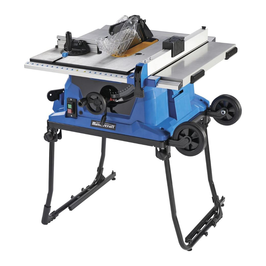
IV. Know your table saw Blade guard Table insert Mitre gauge Rip fence Sliding mitre table Side table Sliding mitre table extension locking lever Blade bevel lock knob Bevel angle pointer and scale Stand handle ON/OFF switch Key Roller wheels Bevel angle pointer and scale Stand leg locking... - Page 9 V . Assembly and adj u stments UNPACKING 1. Carefully remove the table saw from the carton. 2. Separate the parts. 3. Lay out all of the parts, and check them against the parts listed below. Examine all of the parts carefully.
-
Page 10: Installing Batteries For Laser Line
INSTALLING THE BATTERIES FOR THE LASER LINE (FIG. 1) 1. Uninstall the blade guard component by Fig. 1 loosening the handle (1). Remove the locking screw(2) on the battery box cover with a screwdriver, and open the battery compartment. 2. Install two “AAA” batteries. 3. - Page 11 CAUTION LASER RADIATION. Do not stare into the beam or view it directly using optical instruments. Maximum output: <5 mW Wavelength: 630-665 nm Protection Class: IIIA Keep Work Areas Clean Accumulated sawdust and wood chips can pose a safety hazard. each cutting operation.
-
Page 12: Installing Blade To Arbor
V. Assembly and adjustments(continued) INSTALLING THE BLADE TO THE Fig. 4 ARBOR (FIG. 4, 5, 6) 1. Remove the table insert(1)by inserting the finger into the hole (2&3) (see Fig.4). 2. Raise the saw blade arbor (4) to its maximum height by turning the blade raising control handle counter-clockwise. -
Page 13: Assembling The Blade Guard
V. Assembly and adjustments(continued) ASSEMBLING THE BLADE GUARD Fig. 7 (Fig. 7, 8 & 9) VERIFY THAT THE SAW IS DISCONNECTED FROM THE OUTLET BEFORE INSTALLING THE BLADE GUARD AND SPLITTER ASSEMBLY. 1. Use the handwheel to set the blade to the maximum height and to set the tilt to 0°... -
Page 14: Assembling/Adjusting Table Extension Wing
V. Assembly and adjustments(continued) ASSEMBLING THE TABLE Fig. 10 EXTENSION WING (FIG. 10, 11) NOTE: A. Install the extension component (1) (2) into the two holes at the side of the main table. (Fig. 10) B. Install the locking knobs (3) on the aluminum extension wing. - Page 15 V. Assembly and adjustments(continued) ADJUSTING THE MITRE GAUGE Fig. 13 (FIG. 13) 90° 1. Loosen the locking handle (1) in order to allow the mitre body (2) to rotate freely (Fig. 13). Position the mitre body at 90° so that the positive detent secures it in position.
- Page 16 V. Assembly and adjustments(continued) ADJUSTING THE RIP FENCE (FIG. 15) Fig. 15 1. Move the rip fence (1) by releasing the handle (2) and sliding the fence to the desired location. Push the handle down in order to lock the fence into position. 2.
-
Page 17: Adjusting The Blade Height
V. Assembly and adjustments(continued) WARNING: THE BLADE BEVEL LOCKING KNOB (2) MUST BE TIGHTENED SECURELY AND LOCKED DURING ALL CUTTING OPERATIONS.. ADJUSTING THE BLADE HEIGHT (FIG. 16) Turn the control handle (1) CLOCKWISE in order to raise the saw blade. Turn the control handle (1) COUNTER-CLOCKWISE in order to lower the saw blade. - Page 18 V. Assembly and adjustments(continued) 5. If blade is not at a 45° angle to the table, back off the adjustment screw (2). 6. Loosen the bevel locking knob and set the blade at a 45° angle to the table. 7. Once the blade is at a 45° angle to the table top, tighten the bevel angle locking knob 8.
-
Page 19: Unfolding Stand/Assembling Roller Wheels
V. Assembly and adjustments(continued) UNFOLDING THE STAND (FIG. 21) 1. Release the knob (1)(2). 2. Lift the stand up, unfold the wider leg set (3)and unfold the narrower leg set (4). 3. Lock the locking knobs (1)(2). NOTE: Verify that the stand is securely locked in position. 4. - Page 20 V. Assembly and adjustments(continued) FOLDING THE TABLE SAW/STAND (FIG. 23) 1. Rotate the stand locking hook to the left. Lift up the two right-side stand locking levers in order to unlock, and lift the right side of the table saw up slightly off the floor (Fig. 23). Fold the leg set on the right side up to the base of the saw until it snaps into position with the spring clip (Fig.
- Page 21 V. Assembly and adjustments(continued) INSTALLING THE DUST BAG (FIG. 24) Fig. 24 1. Place the dust bag around the neck of the dust port. Tie the dust bag by pulling the drawstring tight, and secure it using the tie-clip. MOUNTING THE TABLE SAW TO A WORKBENCH (FIG.
- Page 22 LIMITED HOOKS AND GUARD PATHHOOKS (Fig. A) 1. Align the holes in the limited hooks (1)and the body of table saw. 2. insert head srew through flat washer and the holes in limtted hooks. 3. Tighten the screws with cross screwdriver. 4.
- Page 23 RAISING THE BLADE (FIG. 24-2) Turn the blade raising control handle (1) COUNTER-CLOCKWISE in order to raise the blade. NOTE: It is not necessary to loosen the blade tilting locking knob (2) when raising or lowering the saw blade. TILTING THE BLADE (FIG. 24-2) Fig.
- Page 24 VI. Operating instructions (continued) USING THE TABLE EXTENSION WING Fig. 25 (FIG. 25) 1. Unlock the table extension wing levers (2) on the two extension tube brackets. 2. Slide the extension tubes in or out until the scale on the front tube is positioned at the desired distance.
- Page 25 V I . Operating instructions (continued) RIPPING (FIG. 26, 26-1) 1. Remove the mitre gauge, and secure the rip fence to the table. 2. Raise the blade until it is approximately 1/8” (3.2 mm) above the top of the workpiece. 3.
-
Page 26: Bevel Ripping
WARNING: •DO NOT ATTEMPT TO PULL THE WORKPIECE BACKWARD WHILE THE BLADE IS TURNING. TURN THE SWITCH OFF, AND WAIT UNTIL THE BLADE HAS COME TO A COMPLETE STOP BEFORE CAREFULLY SLIDING THE WORKPIECE OUT. •DO NOT PERFORM ANY OPERATION FREEHAND. •AVOID KICKBACK BY KEEPING BLADES SHARP, VERIFYING THAT THE RIP FENCE IS PARALLEL TO THE SAW BLADE, AND KEEPING THE SPLITTER, ANTI-KICKBACK PAWLS, AND GUARDS IN PLACE, IN ALIGNMENT, AND FUNCTIONING PROPERLY. - Page 27 V I . Operating instructions (continued) CROSSCUTTING (FIG. 27) CAUTION!To prevent serious injury: •Do not allow familiarity with or frequent use of the table saw to cause careless mistakes. Remember that even a fraction of a second of carelessness is enough to cause a severe injury.
- Page 28 V I . O p erating instructions (continued) BEVEL CROSSCUTTING (FIG. 28) 0° - Fig. 28 45° BLADE BEVEL & 90° MITRE ANGLE This operation is the same as crosscutting, except that the blade is at a bevel angle other than 0°.
- Page 29 USING A WOOD FACING ON THE RIP Fig. 31 FENCE (FIG. 31) When performing certain cutting operations, it is necessary to add a wood facing to either side of the rip fence (2). 1. Use a smooth, straight, 3/4” (19 mm) thick wooden board (1) that is as long as the rip fence.
-
Page 30: Dado Cutting
CAUTION!In order to avoid injury, always replace the blade, the blade guard assembly, and the table insert when once the dado cutting operation has been completed. CAUTION: For safety reasons, turn the power switch OFF, remove the safety key, and unplug the saw from the outlet before performing any maintenance or lubrication. - Page 31 PUSH STICK CONSTRUCTION This is a full-size drawing (actual size) Use good quality plywood or solid wood Use 1/2 in. or 3/4 in.material The push stick MUST be thinner than the width of the material that is being cut Drill Hole For Hanging Notch 0 Prevent the Operator’...
- Page 32 WARNING:In order to avoid injury from an accidental start-up, always turn the switch to the OFF position and unplug the table saw before moving the table saw or the blade, replacing the blade, or making adjustments to the table saw or the blade. SYMPTOM POSSIBLE CAUSES CORRECTIVE ACTION...
- Page 33 This Mastercraft product carries a one ( 3 ) year repair warranty against defects in workmanship and materials. At its discretion, Mastercraft Canada agrees to have any defective part(s) repaired or replaced free of charge, within the stated warranty period, when returned by the original purchaser with proof of purchase.
-
Page 34: Parts List
MASTERCRAFT TABLE SAW WITH SLIDING TABLE When servicing this Mastercraft table saw, use only Mastercraft replacement parts.The use of any other parts may cause damage to the product. All servicing should be performed by a qualified service technician. To find the nearest technician, call the toll- free helpline, at 1-800-689-9928. - Page 35 Description Description Spring pin 4×12 Orientation shaft (A) Uncork ring 9 Rip knife press board Limited piece Rip knife locking knob Spring pin 4×30 Up-down guide column Compaction ring (B) Up-down adjustment screw (B) Limited support seat Flat key 4×8 Spring Up-down adjustment seat Connect shaft (B)
- Page 36 Description Description Wheel bolt Rack (B) Nut M12 Bolt M5×16 Bag clamp Overloading protection Junction box groupware Stand board groupware Hex bolt M5×8 Switch box cover Stand pipe Rubber ring Custer brand Bolt M5×30 Handle Wire block Overloading nut Bolt M5×35 Front cover Switch Inside ring...
- Page 37 Description Description Dado insert hex wrench 5 bolt hex wrench 5...
-
Page 38: Exploded View
18 51 84 22 12 219 220 82 83 84 22 162 163 Imported by Mastercraft Canada Toronto, Canada M4S 2B8...
Need help?
Do you have a question about the 055-6742-8 and is the answer not in the manual?
Questions and answers
replace part 178 circumgyrate wheel
how cant i buy the piece
The document provides a parts list but does not include specific instructions for replacing the circumgyrate wheel (part number 178) on the MasterCraft 055-6742-8. However, based on general practices, follow these steps:
1. Ensure Safety: Disconnect the tool from power and wear protective gear.
2. Locate the Wheel: Identify the circumgyrate wheel (part 178) and any fasteners securing it.
3. Remove Fasteners: Use appropriate tools to loosen and remove bolts, nuts, or clips holding the wheel.
4. Take Out the Old Wheel: Carefully remove the worn or damaged wheel.
5. Install the New Wheel: Position the replacement wheel correctly and secure it using the original fasteners.
6. Check Alignment: Ensure the wheel is properly aligned and rotates smoothly.
7. Test the Functionality: Reconnect power and test the tool to confirm proper operation.
If further details are needed, refer to the product manual or contact MasterCraft support.
This answer is automatically generated
Hello I 'm looking at replacing part #178 circumgyrate wheel, my table saw is no more on warranty, can I purchase the part? saw model 550-6742-8