
Related Manuals for MasterCraft 055-6748-6


Summary of Contents for MasterCraft 055-6748-6
-
Page 1: Instruction Manual
9”Band Saw Item No.:055-6748-6 Instruction Manual Toll-Free Helpline 1-800-689-9928... -
Page 2: Table Of Contents
Assembly and adjustments........... Operating instructions............VII. Maintenance................. VIII. Troubleshooting..............Warranty................Parts list................I.Specifications Model: 055-6748-6 Motor: 120 V~60 Hz 2.5 A Speed: 2556 SFM (surface feet per minute) Blade length: 62" (157.5 cm) Blade width: 1/4" (6.35 mm) Table size: 11 3/4 x 11 3/4”... -
Page 3: General Safety Guidelines
II. General safety guidelines Safety is a combination of common sense, staying alert, and knowing how your band saw works. WARNING! TO AVOID MISTAKES THAT COULD CASE SERIOUS INJURY, DO NOT PLUG IN THE BAND SAW UNTIL YOU HAVE READ AND UNDERSTOOD THE FOLLOWING RULES. - Page 4 II. General safety guidelines (continued) 13. NEVER LEAVE A RUNNING TOOL UNATTENDED. Turn the power switch to the OFF position. DO NOT leave tool until it has come to a complete stop. 14. NEVER STAND ON THE TOOL. Serious injury could result if the tool tips or is accidentally jarred.
- Page 5 II. General safety guidelines (continued) 4. MAKE SURE THE BLADE TEETH POINT DOWN AND TOWARD THE TABLE. 5. BLADE GUIDE, SUPPORTS, BEARINGS AND BLADE TENSION must be properly adjusted in order to avoid accidental blade contact, and to minimize blade breakage. To maximize blade support, always adjust the upper blade guide and blade guard so that it barely clears the workpiece.
-
Page 6: Electrical Information
III. Electrical information GUIDELINES FOR USING EXTENSION CORDS IN THE EVENT OF A MALFUNCTION OR BREAKDOWN, grounding provides the path of least resistance for an electric current and reduces the risk of electric shock. This tool is equipped with a power cord that has an equipment grounding conductor and a grounding plug. The plug MUST be plugged into a matching outlet that is properly installed and grounded, in accordance with ALL local codes and ordinances. - Page 7 III. Electrical information (continued) GUIDELINES FOR USING EXTENSION CORDS Make sure your extension cord is in good condition. When using an extension cord, be sure to use one that is heavy enough to carry the current that your product will draw. An undersized cord will cause a drop in line voltage, which will result in loss of power and overheating.
-
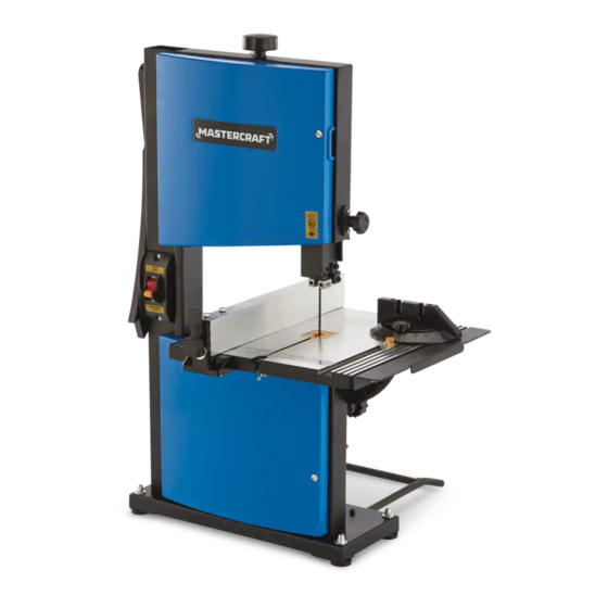
Page 8: Know Your Band Saw
IV. Know your band saw... - Page 9 IV. Know your band saw (continued) Tension knob 12 Working table Blade tension lever 13 On/off switch Tracking knob 14 Upper blade guard Wheel locking blade guide 15. Blade Knob for adjusting the inclination 16. Table support assembly of the table 17. Lower blade guide Table tilt locking knob 18.
-
Page 10: Assembly And Adjustments
V. Assembly and adjustments UNPACKING Carefully unpack the band saw and all of its parts, and compare them against the list below. Do not discard the carton or any packaging until the band saw is completely assembled. WARNING: IF ANY PART IS MISSING OR DAMAGED, DO NOT PLUG THE BAND SAW IN UNTIL THE MISSING OR DAMAGED PART IS REPLACED. - Page 11 V. Assembly and adjustments (continued) ASSEMBLY WARNING: BEFORE ASSEMBLING THE BAND SAW, REMOVE THE SAFETY KEY AND UNPLUG THE POWER CORD FROM THE ELECTRICAL OUTLET. THE POWER CORD MUST REMAIN UNPLUGGED WHENEVER YOU ARE WORKING ON YOUR BAND SAW. Rubber feet mounting (FIG.1) Fig. 1 Before cutting, assemble the four rubber feet to holes in the four corner of base with bolts (M6*30), big flat washers 6, and nuts (M6) as show in picture.
- Page 12 V. Assembly and adjustments (continued) Mounting the working table (FIG.3-5) Fig. 3 - Remove the bolt and wing nut from the hole located in the front edge of table. - Carefully slide the table over the blade, through the slot in the table. Wing Nut - Remove knob assembly from saw frame.
- Page 13 V. Assembly and adjustments (continued) ADJUSTMENTS WARNING: BEFORE ADJUSTING THE BAND SAW, TURN THE SAW OFF, REMOVE THE SAFETY KEY, AND UNPLUG THE POWER CORD FROM THE ELECTRICAL OUTLET. Table tilt adjustment (FIG.7) Fig. 7 The table tilts from 0° to 45° to the right. Lock Lever - Turn the table tilt lock lever counterclockwise.
-
Page 14: Operating Instructions
VI. Operating instructions CAUTION: Always observe the following safety precaution: ● Make sure that blade guides and thrust bearing are positioned and adjusted correctly to prevent sideways and rearward movement of the blade. Adjust upper guide to just clear workpiece. ● Check to make sure blade is tensioned and tracking properly. Do not over tension the blade in order to under tensioning to eliminate back and forth, side to side blade movement as it cuts. -
Page 15: Blade Guides
VI. Operating instruction (continued) NOTE: When closing doors, make sure that the edges attempting to secure door. This is necessary for proper operation of dust collection system. The latches will not pull the doors and frame together. - Install table insert. - Track blade as described in the following sections. Tracking blade Refer to Figures 9 and 12. -
Page 16: Blade Selection
VI. Operating instruction (continued) - Position ball bearing 0.002” away from back of Fig. 11 blade. Bearing - Secure position of bearing by tightening socket head bolt. Socket Head Bolt - Adjust the height of upper guide to clear the workpiece by ”. Loosen upper guide knob and adjust height of upper guide until it clears workpiece ”. -
Page 17: Blade Pitch
VI. Operating instruction (continued) Blade Thickness - Blade thickness describes the distance between sides of blade. A thicker blade has more rigidity and stronger teeth. - A narrow thick blade is used to cut curves while a wide thin blade is used to make long, straight cuts. - Page 18 VI. Operating instruction (continued) Bevel cutting - Perform bevel cutting by tilting table to desired degree. - Unlock table by loosening locking handle located on the backside of the unit. - Tilt table to desired position by rotating knob. - Lock table in position by tightening locking handle. Miter gauge (Fig.13) Fig.
-
Page 19: Maintenance
VII. Maintenance WARNING: Make certain that unit is disconnected from power source before attempting to service or remove any component. Cleaning - Keep machine and workshop clean. Do not allow sawdust to accumulate on band saw. - Keep wheels clean. Debris on wheels will cause poor tracking and blade slippage. - Keep mechanisms and threaded or sliding surfaces clean and free of foreign particles. -
Page 20: Troubleshooting
VIII. Troubleshooting This section describes problems and malfunctions that you should be able to resolve yourself. DANGER: Many accidents happen particularly in connection with problems and faults. Therefore please note: 1. Always unplug before servicing. 2. Check that all safety devices are operational again after each servicing. SYMPTOM POSSIBLE CAUSE(S) CORRECTIVE ACTION... - Page 21 VIII. Troubleshooting (continued) SYMPTOM POSSIBLE CAUSE(S) CORRECTIVE ACTION Teeth ripping from blade Teeth too coarse for work Use blade with finer teeth Rate of feed too great Decrease feed rate Vibrating workpiece Hold workpiece firmly Teeth filling with material Use blade with coarser teeth Motor running too hot Blade too coarse for work Use blade with finer teeth...
-
Page 22: Warranty
IX. Warranty 3-Year Limited Warranty This Mastercraft product is guaranteed for a period of 3 years from the date of original retail purchase against defects in workmanship and materials, except for the following component: Component A: Accessories, which are guaranteed for a period of 1-year from the date of original retail purchase against defects in workmanship and materials. -
Page 23: Parts List
X. Parts list MASTERCRAFT Band Saw 055-6748-6 ® When servicing your Mastercraft Band Saw, use Mastercraft replacement parts only. Use of ® ® any other parts may cause product damage. Any and all servicing of the band saw should be performed by a qualified service technician. - Page 24 X. Parts list (continued) Description Specification Description Specification Bolt M4×6 Clamp handle Bolt M5×10 Spring round pin Indicator Big flat washer Locating sleeve Connecting screw rod Adjusting gear Fixed pressing paw Locating sleeve(A) Guide tube Wave shape washer Hexagon bolt M6×15 Up-down knob Connecting rod Protecting bush Square washer (A)
- Page 25 Imported by Mastercraft Canada Toronto, Canada M4S 2B8...
Need help?
Do you have a question about the 055-6748-6 and is the answer not in the manual?
Questions and answers
Customer service for Part replacement 055–6 748–6
You can contact MasterCraft customer service for part replacement of model 055-6748-6 by calling 1-800-689-9928.
This answer is automatically generated