Advertisement
OPERATING MANUAL
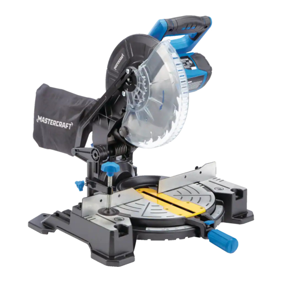
10" COMPOUND MITRE SAW
WITH LASER LINE
055-6717-0
Parts missing or damaged? Questions? Toll-Free Help Line –
1-800-689-9928
IMPORTANT
:
Read through this operating manual carefully before using this tool. Pay
close attention to all Safety Instructions, Warnings, and Caution sections. Use
this tool properly and only for its intended use.
Safety symbols in this manual are used to call attention to possible dangers.
The safety symbols and their explanations require the operator's full under-
standing. The safety warnings do not, by themselves, eliminate any danger, nor
are they a substitute for proper accident-prevention measures.
This Safety Alert Symbol indicates caution, warning, or danger. Failure to
obey a safety warning can result in serious injury to the operator or to others.
To reduce the risk of injury, fire, or electric shock, always follow the safety
precautions.
Advertisement
Table of Contents

Related Manuals for MasterCraft 055-6717-0


Summary of Contents for MasterCraft 055-6717-0
- Page 1 OPERATING MANUAL 10” COMPOUND MITRE SAW WITH LASER LINE 055-6717-0 Parts missing or damaged? Questions? Toll-Free Help Line – 1-800-689-9928 IMPORTANT Read through this operating manual carefully before using this tool. Pay close attention to all Safety Instructions, Warnings, and Caution sections. Use this tool properly and only for its intended use.
-
Page 2: Table Of Contents
TABLE OF CONTENTS Rules for Safe Operation……………………………..………………. Page 3 Glossary of Woodworking Terms………………………………………Page 8 Description…………………………………………………….....Page 9 Assembly……………………..…………………......Page 11 Adjustments....………………….........Page 13 Operation....………………………………......Page 14 Maintenance......…………………........Page 23 Troubleshooting......…………………......Page 23 Repair Parts........…………………......Page 25 Exploded View & Part List....………………......Page 26 Warranty……………………………………………………….……..Page 30 SPECIFICATIONS Mitre Saw Specifications : Motor: 120 V 60Hz 15 A, Speed:... -
Page 3: Rules For Safe Operation
RULES FOR SAFE OPERATION KNOW THE TOOL To operate this tool safely, carefully read this operating manual and all the labels affixed to the Compound Mitre Saw before using it, and follow all instructions contained therein. Retain this manual for future reference. IMPORTANT This tool should only be serviced by a qualified service technician. - Page 4 CAUTION: Always follow the instructions contained in this manual when us- ing this laser. Use of this feature in any manner other than which is directed in this manual may result in a hazardous radiation exposure. • Always wear laser-protective eyewear when working on or near reflective surfaces.
- Page 5 Disconnect tools before servicing the tool and when changing accessories, such as blades, bits, and cutters. Reduce the risk of the tool unintentionally starting. Make sure that the switch is in the OFF position before plugging in the tool. Only use recommended accessories. Consult this Operating Manual for recommended accessories.
- Page 6 Do not modify the plug provided. If it will not fit the outlet, have a proper outlet installed by a qualified electrician. Use only 3-wire extension cords that have 3-prong grounding plugs and 3-pole receptacles that accept the tool’s plug. Permanently connected tools: This tool should be connected to a grounded metal permanent wiring system or to a...
- Page 7 WARNING : Ensure the power supply outlet in question is properly ground- ed. If not sure, have a licensed electrician check the outlet. WARNING : To avoid electrical hazards, fire hazards, or damage to the tool, use proper circuit protection. SPECIFIC SAFETY RULES Use only crosscutting saw blades.
-
Page 8: Glossary Of Woodworking Terms
IMPORTANT: After completing the cut, release the power switch and wait for the blade to stop before returning the saw to the raised position. Make sure that the blade has come to a complete stop before removing or securing the work piece, changing the work-piece angle, or changing the angle of the blade. - Page 9 hand. Use a clamp or vise wherever possible. • Gum: A sticky, sap-based residue from wood products. • Kerf: The material removed by the blade in a through cut or the slot produced by the blade in a non-through or partial cut. •...
-
Page 10: Description
DESCRIPTION KNOW THE COMPOUND MITRE SAW (See Fig. 1) Before attempting to use this Compound Mitre Saw, become familiar with all its operating features and safety requirements. Fig. 1 Fig. 1 Blade Wrench Saw Blade Dust Bag Shop Vacuum Adapter... -
Page 11: Assembly
Installation of dust bag (see Fig.2) Dust bag Make sure that the dust collector bag is right-side-up (reference the Mastercraft logo on the bag), and slide the dust-collector bag’s collar over the dust-extraction port until it is securely attached. - Page 12 Installation of adapter for shop vacuum Remove the dust extraction port for the dust bag by removing the two screws that hold it in place. Attach the shop-vacuum adapter with the same two screws. Release and lock the saw head Fig.
-
Page 13: Adjustments
Make sure that the blade teeth are pointing downward. Install the selected blade by sliding the blade into the upper blade guard and then placing the blade into position. 4. Install the outer flange. IMPORTANT: Make sure the flat side of the flange is placed against the blade. 5. -
Page 14: Operation
Mitre-angle indicator adjustment (if necessary) 1. Place the mitre table at the zero Fig. 6 position, making sure the mitre lock is secured in position. 2. Loosen the mitre-angle indicator screw and adjust the indicator to the “0” mark on the mitre scale. (See Fig. - Page 15 Mitre Saw can be mounted to a supporting surface, such as a level, sturdy worktable or bench. Position the Mitre Saw and workbench to allow adequate room for crosscutting long work pieces. To mount the Mitre Saw, insert fasteners through the four holes in the base of the Mitre Saw and use the fasteners to secure the saw to the table or bench.
- Page 16 clamp the work piece to the mitre table.(See Fig. 8) Aligning the blade WARNING: Do not look into the laser line. • Do not aim the laser line at people or animals. • Do not use the laser line on highly reflective materials. Danger from reflected light.
- Page 17 WARNING : Always keep hands and fingers away from the cutting area. Any part of the body coming into contact with a moving blade will result in serious injury. Stop the Mitre Saw and remove the work piece 1. After completing a cut, release the ON/OFF trigger switch and push the laser ON/OFF switch backward to turn it off.
- Page 18 the fence. If the board is warped, place the convex side against the fence. If the concave edge of the board is against the fence, the board could collapse on the blade at the end of the cut and jam the blade (Figs. 15 and 16).
- Page 19 To Bevel Cut With the Mitre Saw Fig. 13 1. Unplug the saw. WARNING : Failure to unplug the saw could result in accidental starting, cau- sing serious injury. 2. Make sure that the mitre table is at 0°and locked, and check that the mitre-table lock is locked and secured in position.
- Page 20 WARNING: To avoid serious personal injury, always keep hands outside the “no hands zone”, as marked on the saw table, which is at least 3 inches (7.6 cm) from the blade. Also, never perform any cutting operation “freehand” (i.e. without holding the work piece against the fence); the blade could grab the work piece, causing it to slip and twist.
- Page 21 To Make a Compound Mitre Cut with the Mitre Saw 1. Unplug the saw. WARNING: Failure to unplug the saw could result in accidental starting,causing serious injury. 2. Pull out the locking pin to release the saw arm. 3. Loosen the mitre-lock knob to loosen the mitre table. 4.
- Page 22 WARNING: To avoid serious personal injury, always keep hands outside the “no hands zone”, as marked on the saw table, which is at least 3 inches (7.6 cm) from the blade. Also, never perform any cutting operation “freehand” (i.e. without holding the work piece against the fence); the blade could grab the work piece, causing it to slip and twist.
-
Page 23: Maintenance
MAINTENANCE Before cleaning or performing any maintenance, make sure that the Mitre Saw has been disconnected from the power supply. Keep all ventilation openings clean. Avoid using solvents when cleaning plastic parts. Most plastics are susceptible to damage from various types of commercial solvents and may be damaged by their use. - Page 24 Angle of cut Mitre table unlocked Use mitre table locking inaccurate lever See ADJUSTMENT section” Too much sawdust Vacuum or blow out under table dust. Wear Eye Protection! Parts failure Contact CTC Service Cutting arm cannot Centre fully raise, or blade guard cannot fully Pivot spring not Contact CTC Service...
-
Page 25: Repair Parts
Contact CTC Service Centre when the problems remain unsolved after the above checks. Repair Parts INCLUDES: • 1 Pc of 40T carbide tip blades • 1 pc of hold down clamp • 1 pc of dust collection bag • 1 pair of extension rails •... -
Page 26: Exploded View & Part List
Exploded View & Part List Vendor Part # Name Screw 0556717001 Motor cover 0556717002 Screw 0556717003 Brush 0556717004 Brush spring 0556717005 Brush hold 0556717006 Screw 0556717007 Spring washer 0556717008 Washer 0556717009 Motor housing 0556717010 Rubber boot 0556717011 Wave wsher 0556717012... - Page 27 Vendor Part # Name Bearing 0556717013 Armature 0556717014 Stator 0556717015 Washer 0556717016 Spring washer 0556717017 Screw 0556717018 Fan baffle 0556717019 Bearing 0556717020 O-ring 0556717021 Gear lock pin spring 0556717022 Gear lock pin 0556717023 Gear lock pin cap 0556717024 Screw 0556717025 Spring washer 0556717026 Anti-finger touch plate...
- Page 28 Vendor Part # Name Gear washer 0556717058 0556717059 Spindle 0556717060 Bearing 0556717061 Screw 0556717062 Gear case cover 0556717063 Spring washer 0556717064 Screw 0556717065 Blade flange inner 0556717066 Blade 0556717067 Blade flange outer 0556717068 0556717069 Blade bolt Rivet Moving guard Special screw Cast centre Spring Screw...
- Page 29 Vendor Part # Name 0556717103 screw 0556717104 laser 0556717105 laser cover 0556717106 screw Screw Spring washer 0556717107 Washer Bever pointer 0556717111 Bolt 0556717112 Screw 0556717113 Cutting insert Locknut 0556717115 Big washer 0556717116 Turntable 0556717117 Screw Spring washer 0556717118 Washer Miter pointer Clamp plate 0556717122 Spring washer...
-
Page 30: Warranty
Shop-Vacuum Adaptor 0556717157 MASTERCRAFT LIMITED WARRANTY This Mastercraft® product is guaranteed three (3) years from the date of original retail purchase] against defects in materials and workmanship. Subject to the conditions and limitations described below, this product, if returned to us with proof of purchase within the stated warranty period and if covered under this warranty, will be repaired or replaced (with the same model, or one of equal value or specification), at our option. - Page 31 another manufacturer is installed therein or any repairs or alterations have been made or attempted by unauthorized persons; h) This warranty will not apply to normal deterioration of the exterior finish, such as, but not limited to, scratches, dents, paint chips, or to any corrosion or discolouring by heat, abrasive and chemical cleaners;...
Need help?
Do you have a question about the 055-6717-0 and is the answer not in the manual?
Questions and answers