Table of Contents
Advertisement
Quick Links
See also:
User Manual
Advertisement
Table of Contents

Related Manuals for MasterCraft 055-6742-8


Summary of Contents for MasterCraft 055-6742-8
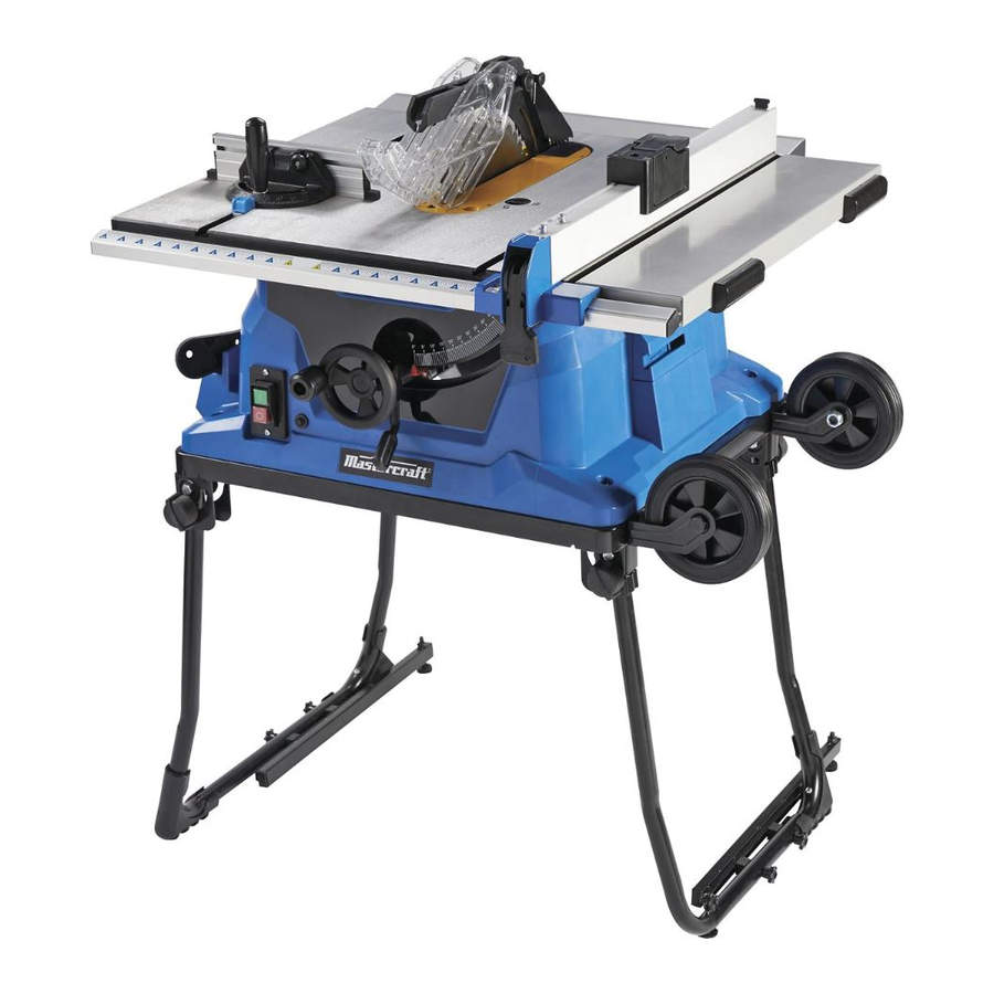
- Page 1 055-6742-8 TABLE SAW WITH FOLD 'N' ROLL STAND IMPORTANT: INSTRUCTION Please read this manual carefully before using this table MANUAL saw and save it for reference.
- Page 2 TABLE OF CONTENTS Quick Start Guide Specifications Safety Guidelines 6-11 Know Your Table Saw 12-16 Assembly Instructions 17-41 Operating Instructions 42-50 Maintenance 51-52 Troubleshooting 53-54 Exploded View 55-57 Parts List 58-61 Warranty NOTE: If any parts are missing or damaged, or if you have any questions, please call our toll-free helpline at 1-800-689-9928 SAVE THESE INSTRUCTIONS This manual contains important safety and operating instructions.
- Page 3 055-6742-8 | contact us 1-800-689-9928 SPECIFICATIONS • Place the table saw (2) on top of the stand (3) and align the mounting holes at Motor 120 V, 60 Hz, 15A the base of the table saw with Speed 4500 RPM (no load) corresponding holes in the stand.
- Page 4 055-6742-8 | contact us 1-800-689-9928 SAFETY GUIDELINES • If you lend this device to other people, always hand over these operating instructions to ensure safe use. Instruct inexperienced people in accordance with these safety instructions. This manual contains information that relates to PROTECTING PERSONAL SAFETY and PREVENTING •...
- Page 5 055-6742-8 | contact us 1-800-689-9928 • Never remove the cutting piece if the machine is still switched on or running. There is a danger of cutting • Use an extension cord when working outdoors. Only use extension cords outdoors that are authorized yourself.
- Page 6 055-6742-8 | contact us 1-800-689-9928 Recommended size for extension cords Do not modify the plug provided. If it will not fit the outlet, have the proper outlet installed by a qualified electrician. Three-prong plug AMPERAGE RATING OF THE TOOL...
- Page 7 055-6742-8 | contact us 1-800-689-9928 Description Description Blade guard Cabinet Rip fence locking handle Mitre gauge storage Rip fence indicator and scale Table insert Bevel scale Right extension table Bevel indicator Rip fence Height adjustment knob Saw blade...
- Page 8 055-6742-8 | contact us 1-800-689-9928 Bevel-locking lever: Arbor: This lever, under the work table surface on the front of the cabinet, locks the angle setting of the blade. The arbor is a shaft on which a blade is mounted.
- Page 9 055-6742-8 | contact us 1-800-689-9928 PACKAGE CONTENTS • Cabinet making and woodworking. Causes of kickback: FOR TABLE SAW Kickback can occur when the blade stalls or binds, causing the workpiece to be kicked back toward the Description Illustration operator with great force and speed.
- Page 10 055-6742-8 | contact us 1-800-689-9928 FOR STAND Description Illustration Description Illustration Push stick Dust bag Blade wrenches Stand assembly 4 mm, 5 mm, 6 mm Hex key Rubber levelling pad with screw ST4.9×40 Rear table extension poles and locating seats...
- Page 11 055-6742-8 | contact us 1-800-689-9928 Description Illustration • Do not discard the packing material until you have carefully inspected and satisfactorily operated the tool. • The saw is factory set for accurate cutting. After assembling it, check for accuracy. If shipping has influenced the settings, refer to specific procedures explained in this manual.
- Page 12 055-6742-8 | contact us 1-800-689-9928 ATTACHING THE ROLLER WHEELS TO THE STAND (Fig. 4) ATTACH THE TABLE SAW TO THE STAND (Fig. 6-7) • Attach the roller wheel supports (1) to the stand using • Place the stand on a level surface, and adjust three hex bolts (2), spring washers (3) and flat washers (4).
- Page 13 055-6742-8 | contact us 1-800-689-9928 MOUNTING THE SAW TO ANOTHER SURFACE (Fig. 8) HEIGHT/BEVEL ADJUSTING HANDWHEEL (Fig. 9) If the stand is not used, the table saw must be properly • Turn the height adjusting knob (1) clockwise to raise secured to a sturdy workbench using the four mounting the blade, and counter-clockwise to lower the blade.
- Page 14 055-6742-8 | contact us 1-800-689-9928 ADJUSTING THE RIVING KNIFE (Fig. 12) • Loosen the tri-wing knob (1) to allow approximately 1/8" (3.2 mm) gap between riving knife (2) and lock plate (3). This saw is shipped with the riving knife placed in “down”...
- Page 15 055-6742-8 | contact us 1-800-689-9928 TO INSTALL ANTI-KICKBACK PAWLS: (Fig. 13-14) CHECK AND ALIGN THE RIVING KNIFE AND SAW BLADE (Fig.17-18) • Unplug the saw. TO CHECK THE ALIGNMENT OF THE RIVING KNIFE: • Pull out and hold knob (1), place the spring pin (2) on •...
- Page 16 055-6742-8 | contact us 1-800-689-9928 TO CHECK SAW BLADE INSTALLATION (Fig. 19) TO REPLACE THE BLADE (Fig. 19-20) The saw is shipped with the blade installed. Prior to initial When you need to replace the saw blade, please follow the...
- Page 17 055-6742-8 | contact us 1-800-689-9928 CHANGING THE BLADE DEPTH (Fig. 21) ADJUSTING THE BEVEL STOPS (Fig. 23-25) The saw blade depth should be set so that the outer points This saw has positive stops that will quickly position the of the saw blade are higher than the workpiece by saw blade at 90°...
- Page 18 055-6742-8 | contact us 1-800-689-9928 ADJUSTING THE BEVEL INDICATOR (Fig. 26) USING THE RIP FENCE (Fig. 28) If the bevel indicator (1) is not at 0° when the saw blade is • Unplug the saw. at 90°, adjust the indicator (1) by loosening the •...
- Page 19 055-6742-8 | contact us 1-800-689-9928 TO ADJUST MITRE GAUGE (Fig. 30) USING THE EXTENSION TABLE (Fig. 31) • Loosen the lock handle in order to allow the mitre body Loosen the locking knobs (2) under the work table, slide the extension table in or out until the extension to rotate freely.
- Page 20 055-6742-8 | contact us 1-800-689-9928 INSTALLING LIMITED HOOKS AND GUARD POT-HOOKS (Fig. 34) TO STORE THE TABLE SAW ACCESSORIES (Fig. 36) The limited hooks and guard pot-hooks are installed at the The table saw has three convenient storage areas...
- Page 21 055-6742-8 | contact us 1-800-689-9928 TO FOLD THE STAND (Fig. 37-39) TO UNFOLD THE STAND (Fig. 40-42) • Loosen the two stand leg-locking knobs (1) provided at • Loosen the two stand leg-locking knobs (1) provided right side of the stand. Fold the narrower leg set (2) at left side of the stand.
- Page 22 055-6742-8 | contact us 1-800-689-9928 BASIC OPERATION OF THE TABLE SAW ALWAYS make sure that your workpiece is not in contact with the blade before operating the switch to start the tool. Failure to heed this warning may cause the workpiece to be kicked back toward the operator, and The three-prong plug must be plugged into a matching outlet that is properly installed and grounded may result in serious personal injury.
- Page 23 055-6742-8 | contact us 1-800-689-9928 RIPPING (Fig. 45) PUSH STICK (Fig. 44) • Remove the mitre gauge, and secure the rip fence to Push sticks are devices used for safely pushing a workpiece through the blade instead of using your hands.
- Page 24 055-6742-8 | contact us 1-800-689-9928 CROSSCUTTING (Fig. 47) BEVEL RIPPING • Remove the rip fence, and place the mitre gauge in This operation is the same as ripping, except that the bevel angle is set to an angle other than 0°.
- Page 25 055-6742-8 | contact us 1-800-689-9928 MITREING 0-45° MITRE ANGLE (Fig. 50) BEVEL CROSSCUTTING 0-45° BLADE BEVEL and 90° MITRE ANGLE (Fig. 48) This sawing operation is the same as crosscutting, except This cutting operating is the same as crosscutting, except that the mitre gauge is locked at an angle other than 90°.
- Page 26 055-6742-8 | contact us 1-800-689-9928 GENERAL MAINTENANCE Make sure that at least one thread of the arbor sticks out past the nut. • Set the riving knife in the fully down position. Avoid using slovents when cleaning plastic parts. Most plastics are susceptible to damage from various types of commercial solvents and may be damaged by their use.
- Page 27 055-6742-8 | contact us 1-800-689-9928 BLADE RAISING AND TILTING MECHANISM (Fig. 53) TROUBLESHOOTING Check the blade raising and tilting mechanism for PROBLEM Possible Causes Solution looseness, binding or other abnormalities after every five hours of operation. Saw will not start.
- Page 28 055-6742-8 | contact us 1-800-689-9928 PROBLEM Possible Causes Solution Material kicked back from • Rip fence out of adjustment. • Align rip fence with mitre gauge blade. slot. • Riving knife not aligned with blade. • Align riving knife with blade.
- Page 29 055-6742-8 | contact us 1-800-689-9928 216 108 217 212 141 143 243 135...
- Page 30 055-6742-8 | contact us 1-800-689-9928 PARTS LIST Description Description Description Description Screw Table insert Scale seat board (A) Ring for shaft 10 Locking ring Hex bolt M6x20 Scale label (B) Fix seat (B) Compaction shaft Main table Square screw M6×16...
- Page 31 055-6742-8 | contact us 1-800-689-9928 Description Description Description Description Miter guide board Circumgyrate handle Damping ring Wheel support Locking nut M5 Circumgyrate knob Brush cap Hex bolt M6x20 Reinforced side panel Handle bolt Brush Hex wrench 5 Rack (B)
- Page 32 055-6742-8 | contact us 1-800-689-9928 3-Year Limited Warranty This Mastercraft product is guaranteed for a period of 3 years from the date of original retail purchase against defects in workmanship and materials, except for the following component: Component A: Accessories, which are guaranteed for a period of 1-year from the date of original retail purchase against defects in workmanship and materials.
Need help?
Do you have a question about the 055-6742-8 and is the answer not in the manual?
Questions and answers
what is the part number for the RIP FENCE for this table saw 055-6742-8
How do I order a part...I need part # 178 ( wheel handle)