Advertisement
Quick Links
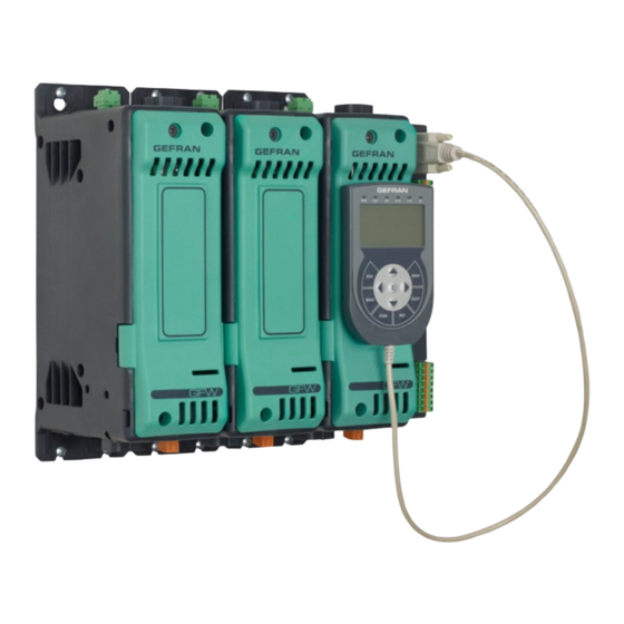
INSTALLATION AND CONNECTION
This section contains the instructions needed
• Supply from Class II or from limited energy
for correct installation of GFW modular power
source.
controller on the machine/host system control
Input and output connections
panel and for correct connection of the power
Before connecting or disconnecting any connection,
supply, inputs, outputs and interfaces.
always check that the power and control cables are
isolated from voltage. Appropriate devices must be
Carefully read the following warnings before
provided: fuses or automatic switches to protect
installing the instrument!
power lines.
Disregard of such warnings could create
The fuses present in the module function solely as a
electrical safety and electromagnetic
protection for the GFW semiconductors.
compatibility problems, as well as void the
• Connected outside circuits must be doubly isolated.
warranty.
• To connect analog inputs, strain gauges, linears,
(TC, RTD), you have to:
ELECTRICAL POWER SUPPLY
- physically separate the input cables from those of
• the controller DOES NOT have an On/Off switch: the
the power supply, outputs, and power connections.
user must install switch/isolator conforming to safety
- use braided and shielded cables, with sheathing
requisites (CE mark) to cut off the power supply
grounded at a single point.
up-line of the controller.
The switch must be installed in the immediate vicinity
Installation notes
of the controller in easy reach of the operator.
Use the extra-rapid fuse indicated in the catalogue
A single switch can be used for multiple devices.
according to the connection example equipped.
* the earth connection must be made with a specific
- Moreover, the applications with solid-state units
lead
require a safety automatic switch to section the load
• if the product is used in applications with risk of
power line. To ensure the high reliability of the device,
harm to persons or damage to machines or
it is necessary to install it properly inside the panel so
materials, it MUST be equipped with auxiliary alarm
to obtain an adequate thermal exchange.
devices.
Fit the device vertically (maximum angle 10° to the
It is advisable to provide the ability to check for tripped
vertical axis)
alarms during regular operation.
• Vertical distance between a device and the panel wall
NOTES ON ELECTRICAL SAFETY AND
>100mm
• Horizontal distance between a device and the panel
ELECTROMAGNETIC COMPATIBILITY:
wall at last 10mm
C E : C o n f o r m i t y E M C
( e l e c t r o m a g n e t i c
• Vertical distance between a device and the next one
compatibility) conformity) in compliance with
at last 300mm.
Directive 2014/30/EU and following modifications.
• Horizontal distance between a device and the next
Series GFW are mainly intended for industrial use,
one at last 10mm.
installed on panels or control panels of production
process machines or systems. For purposes of
Check that the cable holder runners do not reduce
electromagnetic compatibility, the most restrictive
these distances, in this case fit the cantilever units
generic standards have been adopted, as shown on
opposite the panel so that the air can flow vertically
the table.
without any obstacles.
LV (low voltage) conformity in compliance with
• Dissipation of device thermal power with effects on
Directive 2014/35/EU.
installation room temperature.
EMC conformity has been verified with the
• Thermal power dissipation with limits on installation
connections indicated on table 1 (see user's manual).
room temperature.
• Requires exchange with external air or an air
RECOMMENDATIONS FOR CORRECT
conditioner to transfer dissipated power outside the
INSTALLATION FOR PURPOSES OF EMC
panel.
Instrument power supply
• Maximum limits of voltage and derived power of
• The power supply for the electronic instrumentation
transients on the line, for which the solid state
on the panels must always come directly from a cut-
power unit contains protective devices (based on the
off device with fuse for the instrument part.
model).
• Electronic instrumentation and electromechanical
• Presence of dispersion current in GFW in non-
power devices such as relays, contactors,
conducting state (current of a few mA due to RC
solenoids,etc., MUST ALWAYS be powered by
Snubber circuit to protect the thyristor).
separate lines.
• Suitable for use on a circuit capable of delivering not
• When the power supply line of electronic
more than 100,000A RMS Symmetrical Amperes,
instruments is heavily disturbed by switching of
600 Volts maximum when protected by class J fuses
thyristor power groups or by motors, you should
rated xxxA. (Refer to the *SCCR fuse protection table
use an isolation transformer only for the controllers,
this report for the details of the current size fuses for
grounding its she- athing.
each model)
• It is important for the system to be well-grounded:
• Use fuses only.
- voltage between neutral and ground must not be >
ATTENTION: The opening of the branch-circuit
1V
protective device may be an indication that a fault
- Ohmic resistance must be < 6Ω;
has been interrupted. To reduce the risk of fire or
• If the grid voltage is highly unstable, use a voltage
electric shock, current-carrying parts and other
stabilizer.
components of the device should be examined
• In proximity of high-frequency generators or arc
and replaced if damaged. If burnout of the device
welders, use adequate grid filters.
occurs, the complete device must be replaced or
• The power supply lines must be separate from
equivalent.
instrument input and output lines.
GEFRAN S.p.A. assumes no liability for any damage to persons or property deriving from
tampering, from incorrect or improper use, or from any use not conforming to the characteristics
of the controller and to the instructions in this User Manual.
Conformity TC RU-C-IT.A/132.B.00422
CSA
Conformity C/CSA/US CoFC no. 70002856
The device conforms to European Union Directive 2014/30/EU and 2014/35/EU with reference to standards: EN
60947-4-3:2014.
UL
Conformity C/UL/US file no. E243386 vol. 1 sez. 5
SCCR RMS SYM
Short Circuit Current Rating 100KA / 600V according to UL 508
100KA / 600V
ELECTRICAL CONNECTIONS
R
I
F
(O
)
EplaCINg ThE
NTERNal
uSE
pTIONal
CUT OFF POWER BEFORE AND DURING
FUSE SUBSTITUTION PROCEDURE
- Undo the cover fastening screw (1)
- Remove the cover following the movement indicated by
the arrow (2)
- In this way the fuse is discovered (3)
- Slacken the two bolts fixing the fuse in place with a No.19
spanner (GFW 500/600A) or a No.17 spanner (GFW 400A).
There is no need to remove the bolts, as the fuse is pulled
out of its housing as shown by the arrows (5).
- Insert the new fuse as indicated by the arrows (6)
WARNING: the washer must be between the bolt and the
copper strap (NOT under the fuse).
- Tighten the two nuts with a No. 19 spanner (GFW 500/600A)
or a No. 17 spanner (GFW 400A), to a torque of 12 Nm.
- Put the cover back in place, pinning down the top part first
(be careful to hook it on the tooth as shown in the figure).
- Fasten the cover by the specific screw in side (1)
CONNECTIONS
Top View
J6
PE
V-Line
Ground protection
Connector
J5
Connector 3 inputs
3/L1
4/L2
external CT (optional)
(Ref. V_Line)
TA1+
TA1 -
TA2+
J7
TA2 -
V-Load
TA3+
Connector (optional)
TA3 -
1/L1
Power line input
5/T1
6/T2
(DIN or cable)
(Ref. V_Load)
Front View
Magnetic area
keypad xing
GFW-OP
HB Button
DipSwitch
Load con guration
RotarySwitch
Modbus address
J4
3 analog inputs
connector
Out + 5V potentiometer
+INA1
GND
EARTH
+INA2
+INA3
GND
J8-J9
PORT1
RS 485 Modbus RTU
2 RJ11 connector
Dip Switch serial line
INSTALLATION AND OPERATION MANUAL
Side 1
Installation and Connection
Electrical connections
Side 2
Technical-Commercial information
General Information
Dimensions
Bottom View
Fixing/Installation
Derating curves
2/T1
"Load" Output
connection
Tel. 03098881 - fax 0309839063- Internet: http://www.gefran.com
(DIN or cable)
-
DB9
+
Connector
for Keypad
RECOMMENDED WIRE GAUGES
GFW-OP
GFW
CURRENT
TERMINAL
LEVEL
400 A
1/L1, 2/T1
J1 - Auxiliary outputs
400 A
1/L1, 2/T1
connector (optional)
COM
OUT5
400 A
1/L1, 2/T1
OUT6
OUT7
OUT8
400 A
1/L1, 2/T1
J2 - Relay outputs connector
OUT9-OUT10
C (OUT9)
NC
400 A
PE
NO
C (OUT10)
NC
500 A
1/L1, 2/T1
NO
J3 - Power connector and
Digital Inputs 24V
500 A
1/L1, 2/T1
+24Vdc supply
GND
EARTH
+INDIG1
500 A
1/L1, 2/T1
+INDIG2
+INDIG3
+INDIG4
GND
500 A
PE
FIELDBUS (optional)
600 A
1/L1, 2/T1
PORT1
PORT2
PORT3
600 A
1/L1, 2/T1
8 LED STATUS
(con gurable)
600 A
1/L1, 2/T1
RUN.........(Green)
ERROR.....(Red)
DI1...........(Yellow)
DI2...........(Yellow)
600 A
PE
01.............(Yellow)
02.............(Yellow)
03.............(Yellow)
400 / 500 /
J6, J7
BUTTON...(Yellow)
600 A
(*) NOTE: Wires on the ILSCO accessory must be tightened with a hex head wrench n. 8. Torque: 275 lb.in. (31 N-m).
(**) NOTE: Use the IP20 grid of ILSCO accessory code F067432.
(***) NOTE: use only UL cable terminals with their stapler
GFW400...600A
MODULAR POWER
CONTROLLER
code 80498A- 05-2019 - ENG
GEFRAN spa
via Sebina, 74 - 25050 Provaglio d'Iseo (BS)
TYPE CABLE /
TERMINAL TYPE
TIGHTENING /
SECTION
CABLE / RAIL
TOOL TORQUE
TYPE RAIL / SECTION
N. 1 Bolt M12x25mm UNI 5739
Single cable
Wire crimped at terminal tube
hex head wrench n. 18
300 mm
(600kcmil)
Cembre A60-M12
2
Pair: 442.5 lb.in. (50 N-m) (**) (***)
N. 2 Bolts M10x25mm UNI 5739
Double cable
Wire crimped at terminal tube
hex head wrench n. 17
2 x 95 mm
(3/0 AWG)
Cembre A19-M10
2
Pair: 354.0 lb.in. (40 N-m) (***)
N. 1 Bolt M12x25mm UNI 5739
Double cable
Wire stripped for 30mm inserted in
hex head wrench n. 18
2 x 95 mm
2
(3/0 AWG)
ILSCO AU-350 lug (Accessory)
Pair: 442.5 lb.in. (50 N-m) (*) see note
Copper rail
Insulated copper rail with terminal
N. 1 Bolt M12x25mm UNI 5739
(W= width H = height)
non-insulated for
hex head wrench n. 18
W = 40 32 24 mm
L= 60-65mm max
Pair: 442.5 lb.in. (50 N-m)
H = 2
2
3 mm
N. 1 Bolt M10x20mm UNI 5739
Cable 95 mm
2
Wire crimped at terminal tube
hex head wrench n. 17
(3/0 AWG)
Cembre A19-M10
Pair: 354.0 lb.in. (40 N-m) (***)
N. 2 Bolts M10x25mm UNI 5739
Double cable
Wire crimped at terminal tube
hex head wrench n. 17
2 x 120 mm
2
(350 kcmil)
Cembre A24-M10
Pair: 354.0 lb.in. (40 N-m) (***)
N.1 Bolt M12x25mm UNI 5739
Double cable
Wire stripped for 30mm inserted in
hex head wrench n. 18
2 x 120 mm
2
(350 kcmil)
ILSCO AU-350 lug (Accessory)
Pair: 442.5 lb.in. (50 N-m) (*) see note
Copper rail
Insulated copper rail with terminal
N.1 Bolt M12x25mm UNI 5739
(W= width H = height)
non-insulated for
hex head wrench n. 18
W = 50 40 32 mm
L= 60-65mm max
Pair: 442.5 lb.in. (50 N-m)
H = 4
4
5 mm
N. 1 Bolt M10x20mm UNI 5739
Cable 185 mm
Wire crimped at terminal tube
2
hex head wrench n. 17
(350 kcmil)
Cembre A24-M10
Pair: 354.0 lb.in. (40 N-m) (***)
N. 2 Bolts M10x25mm UNI 5739
Double cable
Wire crimped at terminal tube
hex head wrench n. 17
2 x 185 mm
(350 kcmil)
Cembre A37-M10
2
Pair: 354.0 lb.in. (40 N-m) (***)
N.1 Bolt M12x25mm UNI 5739
Double cable
Wire stripped for 30mm inserted in
hex head wrench n. 18
2 x 185 mm
(350 kcmil)
ILSCO AU-350 lug (Accessory)
2
Pair: 442.5 lb.in. (50 N-m) (*) see note
Copper rail
Insulated copper rail with terminal
N.1 Bolt M12x25mm UNI 5739
(W= width H = height)
non-insulated for
hex head wrench n. 18
W = 50 40 32 mm
L= 60-65mm max
Pair: 442.5 lb.in. (50 N-m)
H = 4
4
5 mm
N. 1 Bolt M10x20mm UNI 5739
Cable 185 mm
Wire crimped at terminal tube
2
hex head wrench n. 17
(350 kcmil)
Cembre A37-M10
Pair: 354.0 lb.in. (40 N-m) (***)
Cable 0.25 ... 2.5 mm
2
Cable peeled for 8mm or with a tag
4.425 .... 5.310 lb.in. (0.5 ... 0.6 N-m) /
23 ...14 AWG
terminal
0.6 x 3.5mm slotted screwdriver
Advertisement

Related Manuals for gefran GFW Series


Summary of Contents for gefran GFW Series
- Page 1 DipSwitch H = 4 5 mm +INDIG3 Load con guration GEFRAN S.p.A. assumes no liability for any damage to persons or property deriving from +INDIG4 N. 1 Bolt M10x20mm UNI 5739 Cable 185 mm Wire crimped at terminal tube 500 A hex head wrench n.
- Page 2 TECHNICAL CHARACTERISTICS / GENERAL DATA EXTRARAPID FUSES POWER (SOLID-STATE RELAY) GENERAL DATA Model Size Code Model Power CATEGORY OF USE AC 51 resistive or low inductance loads Power supply GFW 1PH-400/500/600A: 24 Vdc ± 10% max 38W I² t Format Code Dissipated @ In (Tab.
Need help?
Do you have a question about the GFW Series and is the answer not in the manual?
Questions and answers