Table of Contents
Advertisement
Quick Links
1
2
3
3.4.1
3.4.2
3.4.3
3.4.4
3.4.5
3.4.6
80954E_MHW_GF_LOOPER_01-2012_ENG
GF_LOOPER
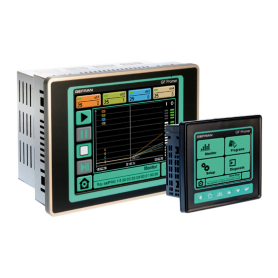
Multiloop graphic controller, 4 - 8 - 12 - 16 zones
3.5" and 5.7" screens, TFT, Colour, Touch screen
GENERAL INDEX
page
2
3
3
4
5
5
5
6
6
7
9
11
11
11
11
12
13
14
14
15
15
15
INSTALLATION AND
OPERATION MANUAL
code 80954E / Edition 06 - 05-2014
4
5
6
7
page
16
17
18
20
21
21
1
Advertisement
Table of Contents

Related Manuals for gefran GF LOOPER


Summary of Contents for gefran GF LOOPER
-
Page 1: Table Of Contents
GF_LOOPER Multiloop graphic controller, 4 - 8 - 12 - 16 zones 3.5” and 5.7” screens, TFT, Colour, Touch screen INSTALLATION AND OPERATION MANUAL code 80954E / Edition 06 - 05-2014 GENERAL INDEX page page Graphic symbols used Preliminary instructions Electrical connections General description Operative notes... -
Page 2: Graphic Symbols Used
Gefran S.p.A. does not issue any type of guarantee with regard to this manual, including but not limited to implicit guarantees of marketability and suitability for a defined purpose. -
Page 3: Preliminary Instructions
1 • PRELIMINARY INSTRUCTIONS This section contains information and warnings of a general nature which should be read before procee- ding with controller installation, configuration and use. General description DATA STORAGE GF_Looper is an advanced series of multichannel con- Trend pages with variable selection and sampling time trollers, offered in configurations of up to 16 channels and configuration (min/sec) offer paperless recording fun- structured for simple use and complete functionality for... -
Page 4: Preliminary Warnings
• Multizone furnaces the installation user’s manual. • Dryers Any inconsistencies, omissions or evident signs of Main characteristics damage should be reported immediately to your Gefran sales agent. • Color graphic display, TFT, 3.5” and 5.7” • Check that the order code corresponds with the touch screen configuration requested for the application the pro- • Complete “On Screen” programming, requires no con-... -
Page 5: Installation And Connection
2 • INSTALLATION AND CONNECTION This section contains the instructions necessary • if the GF_LOOPER is used in applications with risk of for correct installation of the GF_LOOPER into damage to persons, machinery or materials, it is the machine control panel or the host system essential to connect it up to auxiliary alarm and for correct connection of the controller equipment. -
Page 6: Instrument Power Supply
- the voltage between neutral and earth must not be inductive loads that operate in Direct Current. >1V - the resistance must be < 6Ω; • If the mains voltage fluctuates strongly, use a voltage stabilizer. GEFRAN S.p.A. declines all responsibility • In the proximity of high frequency generators or arc for any damage to persons or property welders, use adequate mains filters. caused by tampering, neglect, improper • The power supply lines must be separate from the use or any use which does not conform instrument input and output lines. -
Page 7: Dimensions
Dimensions All measurements are expressed in mm, with tolerance of ± 0.5. GF_LOOPER 35CT dimensions Figure 1 - Dimensions and cut-out Figure 2 - Dimensions 80954E_MHW_GF_LOOPER_01-2012_ENG... - Page 8 GF_LOOPER 57CT dimensions Figure 3 - Dimensions and cut-out Figure 4 - Dimensions 80954E_MHW_GF_LOOPER_01-2012_ENG...
-
Page 9: Fixing
Fixing Panel mounting The GF_LOOPER 35CT and GF_LOOPER 57CT are designed for front panel installation. After making the opening shown on the template drawing, fasten the instrument with the blocks required and sup- plied with the product. Figure 5 - Panel mounting GF_LOOPER 35CT Figure 6 - Panel mounting GF_LOOPER 57CT 80954E_MHW_GF_LOOPER_01-2012_ENG... - Page 10 To maintain IP65 protection level during panel installation, pay attention to the following points: • make the edges of the hole for the panel perfectly smooth and flat • tighten each fastening screw The terminals also have an O-Ring inserted at the rear of the display frames. Figure 7 - O-Ring cover Cleaning the device Clean the device only with a soft cloth and non-abrasive neutral soap.
-
Page 11: Technical Specifications
3 • TECHNICAL SPECIFICATIONS 3.1 Display 35CT: LCD (liquid cristal display) TFT (Thick Film Transistor) color displays measuring 3,5” 57CT: LCD (liquid cristal display) TFT (Thick Film Transistor) color displays measuring 5,7” 3.2 CPUs and Memories The instruments are equipped with EP9307 processors with ARM9 core. Memories: 64MB FLASH mass, 128MB SDRAM system, 512KB cache. -
Page 12: User Connections
3.4 User connections The user connections specified on Table 4 are made at the bottom by means of Gefran standard and custom con- nectors. Figure 9 - Connectors Figure 10 - Connectors Name Description Power supply Ethernet 10/100 Serial RS485... -
Page 13: Power Supply Port
3.4.1 Power supply port The internal power supply 24Vdc is galvanically isolated and protected against polarity reversal and short circuits. The panel has a power terminal. The connector diagram is shown in Figure 11 Note: check that the power supply is able to deliver the power needed for correct operation of the device. The device must always be grounded. -
Page 14: Rs-485 Port
3.4.2 RS-485 port The terminal uses the RS-485 port to dialog according to OSI specifications at the physical level defined by stan- dard EIA-485. The RS-485 port is optically isolated and allows dialog from 9.6 kBaud to 115 kBaud via an RJ10 4p4c connector (Registered Jack type 10 with 4 positions and 4 contacts). -
Page 15: Usb Port
3.4.4 USB port The USB port dialog via USB (Universal Serial Bus) serial communication standard. The terminals support version USB 2.0. The USB port connector is type USB-A (4 pins). Signal assignment is shown in Table 7. Voltage for VBUS is +5V with maximum current of 500mA. Signals D+ and D- refer to the two (pseudo) differential data communication lines. -
Page 16: Electrical Connections
4 • CONNECTION EXAMPLES For all technical characteristics - GFX4 / GFX4-IR / GFXTERMO4 see technical data sheets CONNECTION DIAGRAM GF_LOOPER 57 CT LX0 0 xxxx with GFXTERMO4/ units GF_VEDO 57CT LX0 XX XXXX - LP1 Zone 1-4 9-12 13-16 Modbus RTU S1 S2 S1 S2... -
Page 17: Operative Notes
OPERATIVE NOTES The GF_LOOPER uses external units GFX4 GFX4-IR GFXTERMO4 See the relevant documentation for electrical connections for the above modules/units and to set any parameters not mentioned in this manual. 80954E_MHW_GF_LOOPER_01-2012_ENG... -
Page 18: Table Of Technical Specifications
5 • TABLE OF TECHNICAL SPECIFICATIONS This section contains a list of the Technical Specifications for the Programmer. - Display Type TFT color Number colors 262K Diagonal 3,5” (35CT) 5,7” (57CT) View area display 70,08 x 52,56 mm (35CT) 117,2 x 88,4 mm (57CT) Resolution 320 x 240 Luminosity... - Page 19 ptiOnal nits OdUles Unit for distributed control - GFX4/GFX4-IR 4 zone modular power controller - GFXTERMO4 Modular controller with 4 control zones (see the individual data sheets for characteristics of modular controllers) 80954E_MHW_GF_LOOPER_01-2012_ENG...
-
Page 20: Maintenance
To clean the faceplate and the case use only a cloth and contains a Troubleshooting Guide which should dampened in water or ethyl alcohol. be read before seeking help from the Gefran Do not use hydrocarbon-based solvents Customer Service Assistance, in the event of instru- (trichiorethylene, petrol, etc.). -
Page 21: Technical-Commercial Information
As stated in the Preliminary Warnings of these Instructions for Use, correct interpretation of the Controller order code allows the hardware configuration for the controller to be identified immediately and so it is essential to quote the order code each time the Gefran Customer Care Service is contacted for assistance with any problems. Order code...
Need help?
Do you have a question about the GF LOOPER and is the answer not in the manual?
Questions and answers