Table of Contents
Advertisement
Advertisement
Table of Contents

Related Manuals for Teltonika FM1200


Summary of Contents for Teltonika FM1200
- Page 1 FM1200 User Manual For Product Codes: (G33/10-30V/NiMH battery) V1.7...
-
Page 2: Table Of Contents
NFORMATION ABOUT INTERNAL BATTERY ........................10 USES ................10 LECTRICAL CHARACTERISTICS ................11 BSOLUTE AXIMUM ATINGS CONNECTION, PINOUT, ACCESSORIES ..............11 FM1200 :. 11 OW TO INSERT CARD AND HOW TO CONNECT BATTERY INTO DEVICE FM1200 ................12 NSTALLING DRIVERS LED...................... 13 AVIGATE LED ...................... - Page 3 ....................46 COMMAND LIST 6.1.1 getstatus ..................... 47 6.1.2 getweektime....................47 6.1.3 getops ......................47 6.1.4 getcfgtime ....................48 6.1.5 getgps ......................48 6.1.6 getver ......................48 6.1.7 getinfo ......................48 6.1.8 getio ......................49 6.1.9 readio # ....................... 49 6.1.10 setdigout ## Y1 Y2..................
- Page 4 8.5.2.6 GPRS Week Time (ID=1555) ................59 8.5.3 Roaming Network GSM operator code “Vehicle on STOP” parameters ..59 8.5.3.1 Min Period (ID=1560) ..................59 8.5.3.2 Min Saved Records (ID=1563) ................59 8.5.3.3 Send Period (ID=1564)..................59 8.5.3.4 GPRS Week Time (ID=1565) ................59 8.5.4 Roaming Network GSM operator code “Vehicle MOVING”...
- Page 5 ....................72 ONNECTING IRES ................72 ONNECTING OWER OURCE .................. 72 ONNECTING GNITION .................. 72 ONNECTING ROUND FM1200 ..............73 INSTALLATION INSTRUCTION DOWNLOADING LOG USING “HERCULES” ............76 CHANGE LOG ........................78...
-
Page 6: Introduction
The device uses a 10 V...30 V DC power supply. The nominal voltage is 12 V DC. The allowed range of voltage is 10 V...30 V DC. To avoid mechanical damage, it is advised to transport the FM1200 device in an impact-proof package. Before usage, the device should be placed so that its LED indicators are visible, which show the status of operation the device is in. -
Page 7: Legal Notice
It is important to mention that FM1200 has additional inputs and outputs, which let you control and monitor other devices on remote objects. FM1200 also has a USB port for device status log output and entering configurations. -
Page 8: Basic Characteristics
2.2 Basic characteristics GSM / GPRS features: • Teltonika TM11Q quad band module (GSM 850 / 900 / 1800 / 1900 MHz); • GPRS class 10; • SMS (text, data). GNSS GGG303 Module features: • Navigation Systems; GPS/GLONASS/GALILEO/QZSS; • Protocol NMEA-0183: GGA, GGL, GSA, GSV, RMC, VTG;... -
Page 9: Technical Features
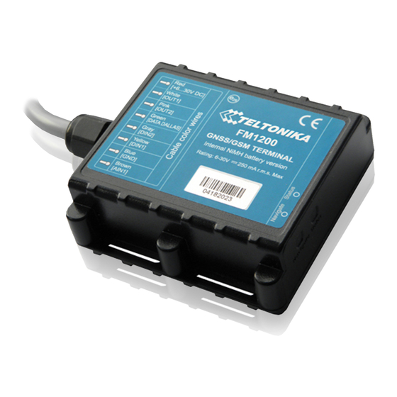
-40 C ... +70 C USB wire (cable is optional) Storage relative humidity 5 ... 95 % (no condensation) Table 1. FM1200 specifications Figure 1. FM1200 view & dimensions (tolerance ±2mm) When in Deep Sleep mode no data storing and sending is activated. -
Page 10: Technical Information About Internal Battery
2.4 Technical Information about internal battery Ni-MH rechargeable battery, 7.2V, 400 mA. FM1200 operating time with internal battery depends on temperature, data sending frequency (SMS and GPRS), and accumulator age, number of charge/discharge cycles. 2.5 Fuses 1. Internal fuse F1 – rated current 5A DC, necessary for the protection of the entire product as a whole. -
Page 11: Absolute Maximum Ratings
Ratings) Analog Input Voltage (Absolute Maximum Ratings) 3 CONNECTION, PINOUT, ACCESSORIES 3.1 How to insert SIM card and how to connect battery into FM1200 device : Open FM1200 case using screwdriver Remove FM1200 case Insert SIM card as shown Connect battery connectoras shown... -
Page 12: Installing Fm1200 Drivers
Teltonika website: http://avl1.teltonika.lt/downloads/FM12/vcpdriver_v1.3.1_setup.zip Installing drivers: Extract and run VCPDriver_V1.3.1_Setup.exe. This driver is used to detect FM1200 device connected to the computer. Click ‘Next’ in driver installation window (figures below): Figure 2. Driver installation window This will launch device driver installation wizard. In the following window click ‘Next’... -
Page 13: Navigate Led
Setup will continue installing drivers and will display a window about successful process at the end. Click ‘Finish’ to complete setup: Figure 4. Driver installation window You have now installed drivers for FM1200 device successfully. 3.3 Navigate LED Behaviour Meaning... -
Page 14: Main Cable Wiring
Figure 5. FM1200 sticker 3.6 USB connection For connecting FM1200 device to PC, special USB cable is used. On one side of the cable there is usual USB plug, which should be connected to PC. Other side of the cable has connector to connect with FM1200. Cable can be connected after removing... - Page 15 Please note that FM1200 device must be connected to the power supply before it can be connected to the PC! When FM1200 is connected to PC, it creates an STM Virtual COM Port, which can be used as a system port (to flash firmware and configure the device):...
-
Page 16: Accessories
Note: Teltonika does not provide any additional equipment like panic buttons, door sensors or others. 1 – Wire devices One of the realized features FM1200 is 1-Wire® data protocol, which enables connection of thermometer (DS1820, DS18S20 and DS18B20) and I-Button type: DS1990A (Figures 8 and 9 show FM1200 and 1-wire®... - Page 17 A fuel tank level sensor exists in most cars, which shows the approximate fuel level in the driver’s indicator panel. It is possible to connect FM1200 Analog input to it (if sensor returns analogue signal proportional to fuel level). Figure shows the connection scheme to the FM1200 and fuel tank sensor.
- Page 18 Figure 11. Inverting relay connection Immobilizer relay When connected as shown below, FM1200 disables engine starter when output is OFF. More details about relays can be found below. Figure 12. Immobilizer relay connection Relays An ordinary automotive relay is used to invert input signal or to immobilize engine starter.
-
Page 19: Firmware
Firmware must to be copied to “Firmware updater” folder. Only one firmware must be in folder. Connect FM1200 to PC with the USB cable. Launch “Firmware Updater”, select COM port to which device is connected, click connect, and when IMEI and Firmware version fields are filled, start the update. -
Page 20: Operational Basics
While in sleep mode, FM1200 turns GPS module off and it is not making new periodic records. Only event records is being recorded with last known coordinate and sent to AVL server. As a... -
Page 21: Deep Sleep Mode
FM1200 can enter sleep mode if ALL of these conditions are met: • FM1200 has to be configured to work in Sleep mode and Sleep timeout is reached; • Device must be synchronized time with GPS satellites; • No movement by movement sensor is detected;... -
Page 22: Virtual Odometer
It keeps adding these intervals until it is time to make a record, then FM1200 records its location and adds odometer value, which is equal to the sum of all distances, measured every second. When record is made, odometer resets to zero and distance calculation starts all over again. -
Page 23: Trip
Next time before driving user has to disable Auto Geofencing with iButton or by turning on car ignition. In case of theft car leaves Auto Geofencing zone without authorization FM1200 device automatically sends high priority record to AVL application. 5.4.4 iButton list iButton list is used to enter authorized iButton ID codes, which are used to authenticate driver in Authorized driving and Auto Geofencing options. -
Page 24: Configuration
FM1200 device, otherwise it will not be written to device. Figure 16. Configurator window (update) FM1200 Configurator is divided into 4 main areas: 1 – main button area, 2 – information area, 3 –settings menu, 4 – parameters and values menu. -
Page 25: Read Records
5.7 Read records When the FM1200 is working in offline mode, it can save up to 100,000 records. Since these records are not sent to the server, they can be downloaded directly to connected computer using USB connection. When you connect FM12 device, FM12XX Configurator appears with additional option “Read Records”... -
Page 26: System Settings
FM1200 can still be configured to acquire and send data to server. It will be possible to store up to 100’000 data records if GSM is not available at the moment. It will send data later when GPRS is available again. -
Page 27: Records Settings
AVL application. Activate Data Link Timeout is used to set timeout of link between FM1200 and AVL application termination. If FM1200 has already sent all records it waits for new records before closing link. -
Page 28: Gsm Settings, Sms Part
Essential fields in ‘SMS’ part are ‘Login’ and ‘Password’. The login and password are used with every SMS sent to FM1200. If login and password are not set, in every SMS sent to FM1200 device two spaces before command have to be used (<space><space><command>). -
Page 29: Gsm Settings, Operator List
Figure 21. Operator list configuration If operator list is left empty, it will allow using GPRS to any GSM operator. Please note that FM1200 will work in Unknown mode only (make sure it is configured to allow data sending – GPRS context is enabled). - Page 30 This functionality allows having different AVL records acquire and send parameters values when object is moving or stands still. Vehicle moving or stop state is defined by Stop Detection Source parameter. There are 3 ways for FM1200 to switch between Vehicle on Stop and Vehicle Moving modes see section 5.7.
- Page 31 (kilobytes) transmitted per session. During the session, FM1200 makes connection and transmits data to a server. FM1200 tries to handle the session as much as possible; it never closes session by itself. Session can last for hours, days, weeks or session can be closed after every connection in certain GSM networks –...
- Page 32 FM1200 sends data to server according to Send period parameter. If it is not, FM1200 checks if it is able to re-establish the session. Figure 24. GPRS Week Time configuration Device checks if the time between last saved record and current time is equal or higher than Time based acquire interval.
-
Page 33: Features Settings
Distance based data acquiring (Min. distance) – records are being acquired when the distance between previous coordinate and current position is greater than defined parameter value. Entering zero disables data acquisition depending on distance. Angle based data acquiring (Min. angle) – records are being acquired when angle difference between last recorded coordinate and current position is greater than defined value. -
Page 34: Trip Settings
5sec. if detected value is over (30; 50] % from preconfigured allowed value 7sec. if detected value is over (50; -] % from preconfigured allowed value After period of time DOUT1 is turned OFF. • Over Speeding DOUT1 is ON, while vehicle speed exceeds parameter value. DOUT1 is activated until current speed decreases below parameter value. -
Page 35: Geofencing Settings
Figure 27. Trip continuous distance counting parameter example 5.14.3 Geofencing settings FM1200 has 5 configurable Geofence zones and it can generate an event when defined Geofence zone border is crossed. Frame border – frame border is an additional border around Geofence zone. It is... - Page 36 Generate event (On entrance, On exit, On Both) – choose when record will be generated; X1 – geofence zone left bottom corner X coordinate (longitude); Y1 – geofence zone left bottom corner Y coordinate (latitude); X2 or R – geofence zone upper right corner X coordinate (longitude) or radius of circle when Circular zone is used (radius in meters);...
-
Page 37: Sms Events
• AutoGeofence • I/O event When any of the above events is triggered, FM1200 sends a configured SMS message to a defined phone number. If SMS events is activated, but there are no numbers defined in SMS events PreDefined Numbers list (figure 1), then the device will not send any... - Page 38 The sent SMS messages format is according to: “Date Time EventText” For example, if FM1200 is configured to send an SMS, when Digital Input 1 reaches High level, with priority High and configured to generate event on both range enter and exit (figure 2), then the sent SMS is: “2012/6/7 12:00:00 Digital Input 1”...
-
Page 39: Sms Events Configuration
ATTENTION! If FM1200 is in Deep Sleep mode and SMS event occurs with LOW priority (which does not wake up FM1200), then the device does not send the message. It is saved in device memory until it wakes up from Deep Sleep mode and GSM modem starts working normally. - Page 40 Figure 4 Trip Start/Stop SMS event configuration Geofence Geofence SMS event is triggered and message sent when the device exits and/or enters a configured Geofence zone. The Geofence zone must be configured to generate an event On Exit, On Enter or On Both (figure 5). If No Event is selected, then it is not possible to turn on SMS events.
-
Page 41: I/Osettings
Figure 6 AutoGeofence SMS event configuration I/O events FM1200 sends SMS event message when a configured I/O property enters and/or exits its configured High/Low boundaries or Hysteresis event generation is chosen (Monitoring does not generate event, so SMS event could not be configured). Every IO element SMS event can be configured to send individual message to different numbers. - Page 42 Permanent I/O elements (are always sent to server if enabled) Property Property Name Bytes Description Digital Input Status 1 Logic: 0 / 1 Digital Input Status 2 Logic: 0 / 1 Digital Input Status 3 Logic: 0 / 1 Analog Input 1 Voltage: mV, 0 –...
- Page 43 Figure 31. I/O settings Enabled or disabled field – allows enabling I/O element so it is added to the data packet and is sent to the server. By default all I/O element are disabled and FM1200 records only GPS coordinates.
-
Page 44: Monitoring
Note: I/O element’s “Movement sensor” Averaging constant is interpreted as Start Move Timeout in seconds (from 1 to 59). Start Move Timeout – is a time interval required for movement sensor to be in the moving state, to consider vehicle as moving. 5.15.1 Monitoring I/O monitoring starts after enabling I/O element and setting up I/O parameters as it is shown below:... -
Page 45: Hysteresis
Low level minimum threshold Generate event on interval enter, on interval exit, on both enter and exit Average constant 1 – 2 (4 Bytes) Figure 33. Digital Input event generation example 5.15.4 Hysteresis Figure 34. Hysteresis parameter configuration I/O elements can generate events according to hysteresis algorithm. If I/O event operand “Hysteresis”... -
Page 46: Sms Command List
FM1200 device. All commands are case sensitive. While FM1200 operates in Deep Sleep mode and user tries to send SMS message it cannot arrive to FM1200 device, because GSM/GPRS module is disabled most of the time (wake up depends on Send Period parameter). -
Page 47: Getstatus
to 40 operator codes, 3 – send all other operator codes sn # Static navigation, 1 – enable, 0 – disable banlist Banned operators information crashlog Device last information before unexpected reset delete_all_sms Deletes all SMS 6.1.1 getstatus Response Description details Data Link Indicate module connection to server at the moment: 0 –... -
Page 48: Getcfgtime
Bootloader Ver Bootloader Version Modem App Ver Version of modem application (veiks: nuo 00.05.14) Firmware revision Example: FW Ver:01.02.16 R1 IMEI:356307044707098 DeviceID:000009 BL Ver:04.00 Modem FW Ver:TM11Q_R_01.03.05.01_002 HW:FM1200.Rev71 NiMH 6-30V 6.1.7 getinfo Response Description details Device Initialization Time RTC Time... -
Page 49: Getio
Number of broken records Profile CRC Fail counter Failed GPRS counter Failed link counter UPD Timeout counter Sent SMS Counter NOGPS No GPS Timer GPS receiver state. 0 – OFF, 1 – restarting, 2 – ON but no fix, 3 – ON and operational, 4 – sleep mode Average satellites Reset Source Identification 1 –... -
Page 50: Getparam
6.1.16 flush #,#,#,#,#,#,# Initiates all data sending by GPRS to specified target server. Comma separated parameters go as numbered: 1.# - IMEI 2.# - APN 3.# - GPRS LOGIN 4.# - GPRS PASSWORD 5.# - IP FM1200 has only one profile (1) -
Page 51: Banlist
Example if unexpected reset was detected: “Crash: 3051,3052,3053”. 7 Debug mode FM1200 is able to transmit its current state when connected to PC using USB cable. It is used to detect errors and provide information to possible solutions when operating as unexpected. Download Terminal from: http://avl1.teltonika.lt/Downloads/Software/Terminal.zip. -
Page 52: Parameter List
(value 0) module will never enter sleep mode, in sleep mode (value 1) module reduces level of power usage by turning GPS module to sleep, in deep sleep mode (value 2) module turns GPS module to sleep and switch GSM module off (note, that FM1200 do not receive SMS while in deep sleep). -
Page 53: Analog Input Value Range (Id=1001)
Acquisition Modes 8.5 Data parameters 8.2.5 Static Navigation (ID=1003) When static navigation is enabled, FM1200 filters out GPS jumps, when it is not moving. When it is disabled, it does not make any changes to collected GPS data. Minimu Maximu... -
Page 54: Server Response Timeout (Id=1012)
m value value d value parameters type Acquisition Modes Data 259200 parameters (Send Period) 8.3.3 Server Response Timeout (ID=1012) Defines time period (in seconds) for server response to sent records. Minimu Maximu Recommende Goes with (depends on) Value m value m value d value parameters... -
Page 55: Apn Username (Id=1243)
Minimu Maximu Recommende Goes with (depends on) Value m value m value d value parameters type GPRS content activation 30 char (ID=1240) Empty S8[30] Name (ID=1242) string APN Password (ID=1244) 8.4.4 APN Password (ID=1244) Parameter defines APN password. In case operator does not use password for login, value should be empty. -
Page 56: Sms Password (Id=1253)
8.4.9 SMS Password (ID=1253) User password is used to ensure module security. Used in every SMS that is sent to device. Example: ab123 Minimu Maximu Recommende Goes with (depends on) Value m value m value d value parameters type SMS Login (ID=1252) Empty 5 char S8[5]... -
Page 57: Data Acquisition Modes Parameters
Minimu Maximu Recommende Goes with (depends on) Value m value m value d value parameters type Empty 7 digits 8.5 Data Acquisition Modes parameters 8.5.1 Home Network GSM operator code “Vehicle on STOP” parameters 8.5.1.1 Min Period (ID=1540) This parameter indicates time interval in seconds in order to acquire new record. If value is 0 it means no records by min period will be saved. -
Page 58: Home Network Gsm Operator Code "Vehicle Moving" Parameters
Sample: GPRS will be allowed on Monday to Friday at 8:00 and 16:00 GMT. The following value should be configured: 00011111 00000000 00000000 00000000 000000000 00000000 00000000 00000001 00000000 00000000 00000000 00000000 00000000 000000001 00000000 00000000 00000000 00000000 00000000 Red bits indicate that GPRS will be allowed every day except Saturdays and Sundays. -
Page 59: Send Period (Id=1554)
Min Angle (ID=1552) GPRS Week Time (ID=1555) 8.5.2.5 Send Period (ID=1554) This parameter indicates frequency (time interval in seconds) of sending data to server. Minimu Maximum Recommende Goes with (depends on) Value m value value d value parameters type 2592000 GPRS Week Time (ID=1545) 8.5.2.6 GPRS Week Time (ID=1555) Read chapter 8.5.1.4 “GPRS Week Time”.. -
Page 60: Min Distance (Id=1571)
8.5.4.2 Min Distance (ID=1571) This parameter indicates distance in meters in order to acquire new record. Record is stored when the distance between previous records is greater than parameter’s value. If value is 0 it means no records by min distance will be saved. Minimu Maximu Recommende... -
Page 61: Unknown Network Gsm Operator Code "Vehicle On Stop" Parameters
m value value d value parameters type 2592000 8.5.5.2 Min Saved Records (ID=1583) This parameter defines minimum number of records in one data packet that can be sent to server. It has higher priority than Data Send Period (ID=1584). Minimu Maximu Recommende Goes with (depends on) -
Page 62: Min Angle (Id=1592)
m value m value d value parameters type Min Period (ID=1570) Min Angle (ID=1572) GPRS Week Time (ID=1575) 8.5.6.4 Min Saved Records (ID=1593) This parameter defines minimum number of records in one data packet that can be sent to server. It has higher priority than Data Send Period (ID=1594). Minimu Maximu Recommende... -
Page 63: Max Angular Velocity (Id=1604)
Minimu Maximu Recommende Goes with (depends on) Value m value m value d value parameters type Digital Output No.1 usage 0.25 0.85 0.35 Float scenarios (ID=1600) 8.6.4 Max Angular Velocity (ID=1604) It is max allowed cornering angle which can be reached while cornering without triggering harsh cornering event. -
Page 64: Trip Continuous Distance Counting (Id=1283)
8.6.10 Trip Continuous distance counting (ID=1283) For this feature I/O#11 ODOMETER must be enabled. If I/O ODOMETER is enabled, and Continuous distance counting variable is set to Continuous (value 1), TRIP distance is going to be counted continuously (from TRIP start to TRIP stop) and shown as I/O ODOMETER value. -
Page 65: Geofence Zone #1 Longitude (X1) (Id=1033)
8.6.11.5 Geofence Zone #1 Longitude (X1) (ID=1033) Parameter has two meanings dependent on zone shape. If shape is a rectangle, then ID=10333 is left down corner X coordinate. If shape is a circle, then ID=1033 is center of that circle X coordinate. Sample value: 25.30528 Minimu Maximu... -
Page 66: Autogeofencing
8.6.12 AutoGeofencing 8.6.12.1 Enable/Disable (ID=1101) Enable – value 1; disable – value 0; Minimu Maximu Recommende Goes with (depends on) Value m value m value d value parameters type 8.6.12.2 Activation Timeout (ID=1102) Parameter represents AutoGeofencing activation timeout in seconds. Minimu Maximu Recommende... -
Page 67: I/Oparameters
m value m value d value parameters type FFFFFFF Digital Output No.2 usage scenarios (ID=1601) FFFFFFF Deactivate by (ID=1100) 8.7 I/O parameters I/O properties are additional data sources which are recorded along with usual GPS data. 8.7.1 I/O#1 property parameter (ID=1300) Parameter defines I/O property value. -
Page 68: I/O#1 Low Level (Id=1303)
8.7.4 I/O#1 Low level (ID=1303) Parameter defines low value of triggered I/O property. This parameter is used to set thresholds for I/O properties to generate events. Minimum Maximum Recommended Goes with (depends on) Value value value value parameters type I/O#1 property parameter (ID=1300) priority (ID=1301) I/O#1... - Page 69 Other I/O property elements can be configured in same logic. All I/O element parameters are listed in the next table. I/O element I/O Element Number parameters I/O#0 – Digital input 1 1300 – 1305 I/O#1 – Digital input 2 1310 – 1315 I/O#2 –...
-
Page 70: I/O#2 Exception For A Digital Input 3/Analog Input Option (Id=1320)
8.7.7 I/O#2 exception for a Digital input 3/Analog input option (ID=1320) Parameter defines I/O property value. Possible values: disabled (0), Digital Input 3 enabled (1), Analog Input enabled (2). Minimu Maximu Recommende Goes with (depends on) Value m value m value d value parameters type... - Page 71 Speed iButton ID Data Mode GSM Signal Deep Sleep Cell ID Area Code Dallas Temperature Reserved Reserved Reserved Reserved Green Driving OverSpeeding Authorized Driving Immobilizer Trip Geo Zone 1 Geo Zone 2 Geo Zone 3 Geo Zone 4 Geo Zone 5 Auto Geofence Reserved Reserved...
-
Page 72: Mounting Recommendations
These points in the car are the battery terminals. Therefore, we recommend connecting the power of FM1200 (wire GND and POWER) directly to the battery terminals. Another valid option is to connect the wires to the main POWER cable inside the fuse box (if there is none, then to the power supply where the fuses of vehicle’s computer are), wire GND must be... -
Page 73: Fm1200 Installation Instruction
(metal free). With not less than ¾ of metal free area. FM1200 has IP67 protection class. It can be mounted outside the vehicle. The device has 4 mounting holes on the edges, and can be tightened with screws, adhesive tape or plastic wires. - Page 74 Most commercial trucks has plastic hood in front of the vehicle. It is recommended to mount FM1200 under the hood. Power cord output of the device should be at the bottom. If it is not possible, if a front hood is made of some kind of metal, the device can be mounted inside the car on the front panel as close as possible to the front window.
- Page 75 Figure 5 Possible mounting places for motorbikes ATV: In ATV FM1200 can be mounted in front of the steering under or on top of the plastic parts. In place where no heat, and maximum possible screen from dirt is. The device cannot be mounted under the seat.
-
Page 76: Downloading Log Using "Hercules
If using Eco driving function device should be mounted horizontally to work properly. It is recommended not to mount FM1200 in direct sunlight places. If the vehicle is not used for a half of month or more it is recommended to disconnect FM1200 to save vehicle battery. - Page 77 3 STEP: “Terminal” Command sending using Hercules...
-
Page 78: Change Log
CHANGE LOG Date Comments sion 2013-03-22 Manual release 2013-03-27 1-Wire connection correction Figure 8 2013-04-02 Module installation correction 2013-07-08 2.5 Fuses added 2013-08-20 Updated mounting instructions, configurator schemes changed, added new topic “Downloading log using “Hercules”” 2013-10-01 Removed unused RILS system description. 2013-10-17 Updated mounting instructions 2013-10-23...
Need help?
Do you have a question about the FM1200 and is the answer not in the manual?
Questions and answers