
Subscribe to Our Youtube Channel
Related Manuals for Teltonika FMB230


Summary of Contents for Teltonika FMB230
- Page 1 FMB230 Quick Manual WATERPROOF GPRS/GNSS v1.4 TRACKER WITH FLEXIBLE INPUTS CONFIGURATION...
-
Page 2: Table Of Contents
Mounting recommendations with a standard cable ....10 Mounting recommendations with U-type cable ...... 11 LED indications ................12 Characteristics................12 Basic characteristics ..............12 Electrical characteristics ..............14 Safety information ..............15 Certification and Approvals ............16 Wiki FMB230 |... -
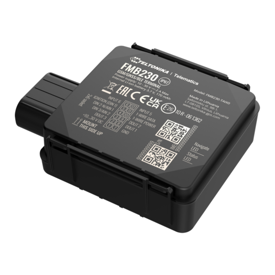
Page 3: Know Your Device
Know your device Figure 1 – FMB230 device view Wiki FMB230 |... -
Page 4: Pinout
Pinout Table 1 FMB230 2x6 socket pinout PIN NUMBER PIN NAME DESCRIPTION VCC (10-30) V DC (+) Power supply (+10-30 V DC). Digital output, channel 3. Open DOUT 3 collector output. Max. 0,5 A DC.. Analog input, channel 2. Input range: 0- DIN 3 / AIN 2 30 V DC / Digital input, channel 3. -
Page 5: Wiring Scheme
Wiring scheme Figure 3 FMB230 Wiring scheme Automotive relay Wiki FMB230 |... -
Page 6: Set Up Your Device
Please make sure that product casing corner clips are fixed tightly and cable is connected to the device in order to maintain the degree of IP67 protection. Figure 8 Attaching cover back Figure 9 Completely closed device Wiki FMB230 |... -
Page 7: How To Install Usb Drivers (Windows)
Setup will continue installing the driver and eventually the confirmation window will appear. Click Finish to complete the 1. Power-up FMB230 with DC voltage (10 – 30 V) power supply setup. using supplied power cable. LED’s should start blinking, see “LED indications”. - Page 8 Most important configurator section is GPRS – where all your server and GPRS settings can be configured and Data Acquisition – where data acquiring parameters can be configured. More details about FMB230 configuration using Configurator can be found in our Wiki. Figure 12 Configurator Status window Wiki FMB230 |...
-
Page 9: Quick Sms Configuration
120 seconds 2006 – Data sending protocol • After successful SMS configuration, FMB230 device will (0 – TCP, 1 – UDP) synchronize time and update records to configured server. Time intervals and default I/O elements can be changed by using Teltonika Configurator parameters. -
Page 10: Mounting Recommendations With A Standard Cable
▬ For better contact scrub paint from the spot where loop is power might be still available on the power wires. going to be connected. Depending on the car model, this may happen in 5 to 30 minutes period. Wiki FMB230 |... -
Page 11: Mounting Recommendations With U-Type Cable
Device power wire is designed to be directly connected to ▬ the positive terminal fastener of the vehicle battery • Connecting ground wire ▬ Device ground wire is designed to be directly connected to the negative terminal fastener of the vehicle battery. Figure 13 Device mounting Wiki FMB230 |... -
Page 12: Led Indications
Device is not working or Device is in CELLULAR boot mode Technology 2G bands Quad-band 850 / 900 / 1800 / 1900 MHz GPRS Multi-Slot Class 12 (up to 240 kbps), Data transfer GPRS Mobile Station Class B Data support SMS (text/data) Wiki FMB230 |... - Page 13 LED indication 2 status LED lights GPRS commands Configuration, DOUT control, Debug Micro-SIM + eSIM Time Synchronization GPS, NITZ, NTP Memory 128MB internal flash memory LLS (Analog), LV-CAN200, ALL-CAN300, PHYSICAL SPECIFICATION Fuel monitoring OBDII dongle, CAN-CONTROL, OBDII dongle Wiki FMB230 |...
-
Page 14: Electrical Characteristics
Input voltage (Recommended Operating Supply Input resistance (DIN2) 38.45 kΩ Conditions) voltage Input resistance (DIN3) kΩ Input voltage threshold Sink current Input voltage (Recommended Operating Supply Conditions) voltage Input Voltage threshold (DIN1) Input Voltage threshold (DIN2) Wiki FMB230 |... -
Page 15: Safety Information
CAUTION: Risk of explosion if battery is replaced by an incorrect type. Dispose of used batteries according to The device FMB230 is not designed as a navigational device for boats. the instructions. Do not disassemble the device. If the device is... -
Page 16: Certification And Approvals
User‘s Manual before your start using the device. Full User‘s Manual version can be found in our Wiki. This sign on the package means that all used electronic and electric equipment should not be mixed with general household waste. Wiki FMB230 |... -
Page 17: Warranty
More information can be found at teltonika.lt/warranty-repair • Repaired • Replaced with a new product • Replaced with an equivalent repaired product fulfilling the same functionality • TELTONIKA can also repair products that are out of warranty at an agreed cost. Wiki FMB230 |...
Need help?
Do you have a question about the FMB230 and is the answer not in the manual?
Questions and answers