Table of Contents
Advertisement
Quick Links
Advertisement
Table of Contents

Subscribe to Our Youtube Channel
Related Manuals for Teltonika FM1100


Summary of Contents for Teltonika FM1100
- Page 1 FM1100 User Manual v0.17...
-
Page 2: Table Of Contents
ACKAGE CONTENTS ....................8 ASIC CHARACTERISTICS ....................9 ECHANICAL FEATURES ..................11 LECTRICAL CHARACTERISTICS ..................11 BSOLUTE AXIMUM ATINGS CONNECTION, PINOUT, ACCESSORIES..............12 ....................12 CARD INSERT SCHEME FM1100 ..................13 NSTALLING DRIVERS LED ......................15 AVIGATE LED........................15 TATUS 2×5 ........................15 OCKET USB..........................16 .......................17 CCESSORIES FIRMWARE........................20 ................20... - Page 3 6.1.2 getweektime..................... 43 6.1.3 getops ......................43 6.1.4 getcfgtime....................44 6.1.5 getgps......................44 6.1.6 getver......................44 6.1.7 getinfo......................44 6.1.8 getio ......................45 6.1.9 readio # ..................... 45 6.1.10 setdigout ##....................45 6.1.11 getparam ####..................46 6.1.12 setparam #### # ..................46 6.1.13 flush #,#,#,#,#,#,# ...................
- Page 4 8.5.4 Roaming Network operator code “Vehicle MOVING” parameters 8.5.4.1 Min Period (ID=1570)....................54 8.5.4.2 Min Distance (ID=1571) ..................54 8.5.4.3 Min Angle (ID=1572) ....................55 8.5.4.4 Min Saved Records (ID=1573)................55 8.5.4.5 Send Period (ID=1574)....................55 8.5.4.6 GPRS Week Time (ID=1575) ...................55 8.5.5 Unknown Network operator code “Vehicle...
- Page 5 ..................65 ONNECTING OWER OURCE ..................65 ONNECTING GNITION ..................65 ONNECTING ROUND .....................65 ONNECTING NTENNAS ....................66 ODULE NSTALLATION CHANGE LOG ......................67...
-
Page 6: Introduction
PC <-> FM1100 connection. 1.2 Instructions of safety This chapter contains information on how to operate FM1100 safely. By following these requirements and recommendations, you will avoid dangerous situations. You must read these instructions carefully and follow them strictly... -
Page 7: Legal Notice
SMS – Short Message Service. AC/DC – Alternating Current/Direct Current. I/O – Input/Output. Record – AVL data stored in FM1100 memory. AVL data contains GPS and I/O information AVL packet - Data packet that is being sent to server during data transmission. -
Page 8: Package Contents
It is important to mention that FM1100 has additional inputs and outputs, which let you control and monitor other devices on remote objects. FM1100 also has a USB port for device status log output and entering configurations. -
Page 9: Mechanical Features
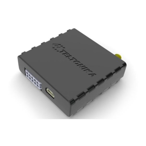
Storage temperature: Socket 2 5 -40 C ... +70 C 4-794628-0 or similar Storage relative humidity 5 ... Mini USB socket 95 % (non condensation) Table 1. FM1100 specifications When in Deep Sleep mode no data storing and sending is activated. - Page 10 Figure 2. FM1100 view & dimensions (tolerance ±2mm)
-
Page 11: Electrical Characteristics
2.4 Electrical characteristics Min. Typ. Max. Unit Supply Voltage: Supply Voltage (Recommended Operating Conditions) Digital Output (Open Drain grade): Drain current (Digital Output OFF) Drain current (Digital Output ON, Recommended Operating Conditions) Static Drain-Source resistance mOhm (Digital Output ON) Digital Input: Input resistance (DIN1, DIN2, DIN3) kOhm Supply... -
Page 12: Connection, Pinout, Accessories
Drain-Source clamp threshold voltage (Absolute Maximum Ratings), = 2mA drain Digital Input Voltage (Absolute Maximum Ratings) Analog Input Voltage (Absolute Maximum Ratings) 3 CONNECTION, PINOUT, ACCESSORIES 3.1 SIM card insert scheme Gently open FM1100 case using screwdrivers... -
Page 13: Installing Fm1100 Drivers
Take off FM1100 case Insert SIM card as shown Assemble device top part Device is ready 3.2 Installing FM1100 drivers Software requirements • Operating system 32-bit and 64-bit: Windows XP with SP3 or later, Windows Vista, Windows 7. • MS .NET Framework V3.5 or later (http://www.microsoft.com... - Page 14 Teltonika website: http://avl1.teltonika.lt/downloads/FM11/vcpdriver_v1.3.1_setup.zip Installing drivers Extract and run VCPDriver_V1.3.1_Setup.exe. This driver is used to detect FM1100 device connected to the computer. Click 'Next' in driver installation window (figures below): Figure 3. Driver installation window This will launch device driver installation wizard. In the following window click ‘Next’...
-
Page 15: Navigate Led
Figure 5. Driver installation window You have now installed drivers for FM1100 device successfully. 3.3 Navigate LED Behaviour Meaning Permanently switched on GPS signal is not received Blinking every second Normal mode, GPS is working GPS is turned off because: Deep sleep mode •... -
Page 16: Usb
Table 2. Socket 2x5 pinout description. 3.6 USB Mini USB connector Figure 7. Mini USB type B connector FM1100 connected to PC creates STM Virtual COM Port, which can be used as system port (to flash firmware and configure the device). Figure 8. COM-Ports... -
Page 17: Accessories
1 – Wire devices One of the FM1100 features is realized 1-Wire® data protocol, which enables connection of thermometer (DS1820, DS18S20 and DS18B20) and I-Button type: DS1990A. Figures 9 and 10 shows FM1100 and 1-wire® devices connection schemes. - Page 18 A fuel tank level sensor exists in most of the cars, which shows the approximate fuel level in the driver’s indicator panel. It is possible to connect FM1100 Analog input (if sensor returns analogue signal proportional to fuel level). Figure shows the connection scheme to the FM1100 and fuel tank sensor.
- Page 19 Figure 12. Inverting relay connection Immobilizer relay When connected as shown below, FM1100 disables engine starter when output is OFF. More details about relays can be found below. Figure 13. Immobilizer relay connection...
-
Page 20: Firmware
Updater is needed to update the firmware. It can be downloaded from: http://avl1.teltonika.lt/downloads/FM11/ Firmware must to be copied to “Firmware updater” folder. Connect FM1100 to PC with USB cable. Launch “Firmware Updater”, select COM port, click connect and update. Update process may take up to several minutes. -
Page 21: Updating Firmware Via Gprs
FM1100 processor firmware. In order to update firmware, server sends a SMS to the FM1100 and directs it to connect to the server and download new firmware. The special web interface is used for this operation. Address of the web application is: http://212.47.99.62:5002/RILS-web/. -
Page 22: Operational Basics
5 OPERATIONAL BASICS 5.1 Operational principals FM1100 module is designed to acquire records and send them to the server. Records contain GPS and I/O information. Module uses GPS receiver to acquire GPS data and is powered with three data acquire methods: time-based, distance-based and angle-based method. -
Page 23: Virtual Odometer
It keeps adding these intervals until it is time to make a record, then FM1100 records its location and adds odometer value, which is equal to the sum of all distances, measured every second. When record is made, odometer resets to zero and distance calculation starts all over again. -
Page 24: Trip
• Vehicle speed is equal or higher than 30km/h Note: Green Driving Scenario is in on various cars and various drivers testing phase and can be subject to changes. Teltonika is constantly working on improvement of the functionality of the devices, and strongly recommends using the latest version of the firmware. -
Page 25: Configuration
Modem IMEI and firmware version of your device (figure below). FM1100 has one user editable profile, which can be loaded from device, and saved. User can also revert to default settings, by pressing Load Defaults button. After any modification of configuration settings it has to be saved to FM1100 device, otherwise it will not be written to device. -
Page 26: System Settings
FM1100 Configurator is divided into 4 main areas: 1 – main button area, 2 – information area, 3 –settings menu, 4 – parameters and values menu. Button description: ‘Connect’ – connects device ‘Load’ – reads configuration parameters from FM1100 Flash memory. -
Page 27: Records Settings
AVL application. Activate Data Link Timeout is used to set timeout of link between FM1100 and AVL application termination. If FM1100 already sent all records it waits for new records before closing link. -
Page 28: Gsm Settings, Sms Part
Essential fields in ‘SMS’ part is ‘Login’ and ‘Password’. This login and password is used with every SMS sent to FM1100. If login and password is not set, in every SMS send to FM1100 device two spaces before command has to be used (<space><space><command>). -
Page 29: Gsm Settings, Operator List
5.11 GSM settings, Operator list Operators list – FM1100 is able to use GPRS with all operators, but if at least one operator is entered in the list, FM1100 is allowed to connect to GPRS only while operating in listed operator’s network. - Page 30 As result, FM1100 allows to have 6 different modes. Operational logic is shown Figure . If there are no operator codes entered into operator list, FM1100 will work in Unknown network mode. Figure 23. Data Acquisition Mode configuration Operator search is performed every 15 minutes. Depending on current GSM operator, Home, Roaming or Unknown mode can be changed faster than every 15 minutes.
- Page 31 At scheduled time match FM1100 checks for GPRS session activity. If GPRS session is alive, FM1100 sends data to server according to Send period parameter. If it is not, FM1100 checks if it is able to re- establish the session.
-
Page 32: Features Settings
FM1100 is able to collect records using three methods at the same time: time, distance and angle based data acquisition: Time based data acquiring (Min. period) – records are being acquired every time when defined interval of time passes. Entering zero disables data acquisition depending on time. -
Page 33: Scenarios Settings
5.13.1 Scenarios settings In Scenarios window four different scenarios are available, two per each Digital Output (DOUT). Only one per digital output can be active at a same time, e.g. DOUT1 can have either Green driving or Over Speeding enabled, DOUT2 can have either Authorized Driving or Immobilizer enabled. -
Page 34: Trip Settings
DOUT2 is ON continuously, after 1 minute blinks with 300 ms duty cycle if iButton is not connected. DOUT2 turns OFF, after iButton is connected. After successful deactivation of immobilizer DIN1 (ignition) can be turned OFF for no longer than 30 seconds, otherwise Immobilizer security will be turned on and deactivation must be repeated. -
Page 35: Geofencing Settings
Figure 27. Trip continuous distance counting parameter example 5.13.3 Geofencing settings Geofencing settings FM1100 has 5 configurable Geofence zones and it can generate event when defined Geofence zone border is crossed. Frame border – frame border is an additional border around Geofence zone. -
Page 36: Settings
Priority – priority of Geofence event: low, high or panic. These levels define priority of event information sending to server. See I/O element description for more details about priorities. Generate event (On entrance, On exit, On Both) – choose when record will be generated;... -
Page 37: I/O Settings
Geofence will be created around vehicle last position by set Radius value. Auto Geofence event generation works the same as Geofencing mentioned above. Figure 30. Geofence configuration Note FM1100 operates GMT time without daylight saving. 5.14 I/O settings When no I/O element is enabled, AVL packet comes with GPS information only. - Page 38 10 * Degrees ( °C ), -55 - +115, if Dallas Temperature 3000 – Dallas error iButton Input iButton ID number 0 – home on stop, 1 – home on move, 2 – roaming on stop, 3 – Working mode roaming on move, 4 –...
- Page 39 FM1100 records only GPS coordinates. Priority – AVL packet priority – low, high or panic. Regular packets are sent as Low priority records. When low priority event is triggered, FM1100 makes additional record with indication that the reason for that was I/O element change.
-
Page 40: Monitoring
5.14.1 Monitoring I/O monitoring starts after enabling I/O element and setting up I/O parameters as it is shown below: Figure 32. I/O settings 5.14.2 Event Generating Events happen when the value of enabled I/O intersects thresholds (enter, exit or on both) predefined by High and Low level thresholds. Table below defines all available values of I/O settings. -
Page 41: Hysteresis
5.14.3 Hysteresis I/O elements can generate events according to hysteresis algorithm. If I/O event operand “Hysteresis” is selected, events will be generated as it is shown in the illustration below: Figure 104. Event generation according hysteresis algorithm... -
Page 42: Sms Command List
6 SMS COMMAND LIST Read chapter 5.10 to know how to construct proper SMS message and send it to FM1100 device. All commands are case sensitive. While FM1100 operates in Deep Sleep mode and user tries to send SMS message it could not arrive to FM1100 device, because GSM/GPRS module is disabled most of the time (wake up depends on Send Period parameter). -
Page 43: Getstatus
4.# - PASS 5.# - IP 6.# - PORT 7.# - MODE (0-TCP/1-UDP) 6.1.1 getstatus Response details Description Data Link Indicate module connection to server at the moment: 0 – Not connected, 1 – connected GPRS Indicate if GPRS is available at the moment Phone Voice Call status: 0 –... -
Page 44: Getcfgtime
6.1.4 getcfgtime Response Description details Date/Time Returns last performed configuration date and time. Example: Last Configuration was performed on: 2010.4.15 5:45:19 6.1.5 getgps Response Description details Indicates valid (1) or invalid (0) GPS data Count of currently available satellites Latitude (Last good Latitude) Long Longitude (Last good Longitude) Altitude... -
Page 45: Getio
Error Counter Number of Sent Records Number of broken records Profile CRC Fail counter Failed GPRS counter Failed link counter UPD Timeout counter Sent SMS Counter NOGPS No GPS Timer GPS receiver state. 0 – OFF, 1 – restarting, 2 – ON but no fix, 3 –... -
Page 46: Getparam
6.1.11 getparam #### Read parameter value. ID consists of 4 digits – first digit identifies profile, second, third and fourth identifies parameter ID as described in Parameter List chapter. Response Description details Profile number and parameter ID Value Parameter value Example: ‘getparam 1245’... -
Page 47: Debug Mode
Records to Send: 1. GPRS Enabled: 1. Time Sync: 1. 7 Debug mode FM1100 is able to transmit its current state when connected to PC using USB cable. It is used to detect errors and provide information to possible solutions... -
Page 48: System Parameters
8.2 System parameters 8.2.1 Deep Sleep Mode (ID=1000) Device can operate in two modes: active or deep sleep. In active mode (value 0) module is able to operate all tasks, while in deep sleep mode (value 1) module reduces level of power usage. Minimu Maximu Recommen... -
Page 49: Gsm Parameters
8.4 GSM parameters 8.4.1 GPRS content activation (ID=1240) Parameter allows or does not allow using GPRS. If GPRS is not allowed value is 0, if GPRS is allowed value is 1. Minimu Maximu Recommen Goes with (depends on) Value m value m value ded value parameters... -
Page 50: Target Server Ip Address (Id=1245)
8.4.5 Target Server IP address (ID=1245) Parameter defines AVL data destination server IP address. Example: 212.47.99.62 Minimu Maximu Recommen Goes with (depends on) Value m value m value ded value parameters type GPRS content activation 16 char (ID=1240) Empty S8[16] Target Server IP address string (ID=1245) -
Page 51: Sms Data Send Week Time Schedule (Id=1273)
Minimu Maximu Recommen Goes with (depends on) Value m value m value ded value parameters type SMS Data send week time schedule (ID=1273) 8.4.11 SMS Data send week time schedule (ID=1273) Parameter defines SMS data sending according to week time schedule. This parameter is used to set data sending on selected week days and hours. -
Page 52: Send Period (Id=1544)
GPRS Week Time (ID=1545) 8.5.1.3 Send Period (ID=1544) This parameter indicates frequency (time interval in seconds) of sending data to server. Minimu Maximu Recommen Goes with (depends on) Value m value m value ded value parameters type Min Saved Records 9999999 (ID=1543) GPRS Week Time (ID=1545) -
Page 53: Min Distance (Id=1551)
GPRS Week Time (ID=1555) 8.5.2.2 Min Distance (ID=1551) This parameter indicates distance in meters in order to acquire new record. Record is stored when the distance between previous records is greater than parameters value. If value is 0 it means no records by min distance will be saved. Minimu Maximu Recommen... -
Page 54: Roaming Network Gsm Operator Code "Vehicle On Stop" Parameters
8.5.3 Roaming Network GSM operator code “Vehicle on STOP” parameters 8.5.3.1 Min Period (ID=1560) This parameter indicates time interval in seconds in order to acquire new record. If value is 0 it means no records by min period will be saved. Minimu Maximu Recommen... -
Page 55: Min Angle (Id=1572)
8.5.4.3 Min Angle (ID=1572) This parameter indicates angle in degrees in order to acquire new record. If angle difference between last recorded coordinate and current position is greater than defined value, new record is stored. This parameter is operational, when speed is higher than 10km/h. If value is 0 it means no records by min angle will be saved. -
Page 56: Min Saved Records (Id=1583)
8.5.5.2 Min Saved Records (ID=1583) This parameter defines minimum number of records in one data packet that can be sent to server. It has higher priority than Data Send Period (ID=1584). Minimu Maximu Recommen Goes with (depends on) Value m value m value ded value parameters... -
Page 57: Min Saved Records (Id=1593)
m value m value ded value parameters type Min Period (ID=1570) Min Angle (ID=1572) 65535 GPRS Week Time (ID=1575) 8.5.6.4 Min Saved Records (ID=1593) This parameter defines minimum number of records in one data packet that can be sent to server. It has higher priority than Data Send Period (ID=1594). Minimu Maximu Recommen... -
Page 58: Max Braking Force (Id=1603)
8.6.2 Max Braking Force (ID=1603) It is max allowed braking force which can be reached while braking without triggering harsh braking event. Minimu Maximu Recommen Goes with (depends on) Value m value m value ded value parameters type Digital Output No.1 usage 0.25 0.85 0.35... -
Page 59: Ignition Off Timeout (Id=1282)
8.6.8 Ignition Off Timeout (ID=1282) This parameter represents timeout to wait if ignition is off in order to detect TRIP STOP and generate event. Minimu Maximu Recommen Goes with (depends on) Value m value m value ded value parameters type 65535 Trip (ID=1280) 8.6.9 Trip Continuous distance counting (ID=1283) -
Page 60: Geofence Zone #1 Longitude (X1) (Id=1033)
Minimu Maximu Recommen Goes with (depends on) Value m value m value ded value parameters type All Geofencing parameters 8.6.10.5 Geofence Zone #1 Longitude (X1) (ID=1033) Parameter has two meanings dependent on zone shape. If shape is rectangular, then ID=10333 is left down corner X coordinate. If shape is circle, then ID=1033 is center of that circle X coordinate. -
Page 61: Autogeofencing
GeoFen Geofence ce Zone Zone’s Number parameters 1030-1036 1040-1046 1050-1056 1060-1066 1070-1076 8.6.11 AutoGeofencing 8.6.11.1 Enable/Disable (ID=1101) Enable – value 0; disable – value 1; Minimu Maximu Recommen Goes with (depends on) Value m value m value ded value parameters type 8.6.11.2 Activation Timeout (ID=1102) -
Page 62: Radius (Id=1105)
(ID=1103) 8.6.11.6 Radius (ID=1105) Parameter represents radius of circle with center device coordinates after activating AutoGeofence feature. Minimu Maximu Recommen Goes with (depends on) Value m value m value ded value parameters type 4294967 Enable/Disable (ID=1101) Deactivate by (ID=1100) 8.6.12 iButton List (ID=1610-1659) Read 5.4.4. -
Page 63: Io#1 High Level (Id=1302)
IO#1 averaging length (ID=1305) 8.7.3 IO#1 High level (ID=1302) Parameter defines high value of triggered IO property. This parameter is used to set thresholds for IO properties to generate events. Minimu Maximu Recommen Goes with (depends on) Value m value m value ded value parameters... - Page 64 Minimu Maximu Recommen Goes with (depends on) Value m value m value ded value parameters type IO#1 property parameter (ID=1300) IO#1 priority (ID=1301) 214748364 IO#1 High level (ID=1302) IO#1 Low level (ID=1303) IO#1 logic operand (ID=1304) Other IO property elements are configuring in same logic. All IO elements parameter list is below.
-
Page 65: Mounting Recommendations
• For better contact scrub paint from the place where loop is connected. 9.5 Connecting Antennas • When placing antennas avoid easily reached places. • Avoid GPS antenna placement under metal surfaces. • Avoid placing FM1100 device near car radio, speakers or alarm systems. -
Page 66: Module Installation
It is recommended to place GPS antenna behind dashboard as close to the window as possible. A good example of GPS antenna placement is displayed in a picture below (area colored green). Figure 11. Correct placement of FM1100 9.6 Module Installation • Module should not be seen or easily reached. -
Page 67: Change Log
• Module should be firmly fixed to the surface or cables. • Module cannot be fixed to heat emitting or moving parts. • SIM card should be inserted in the module while the connector is plugged off (while module has no power). 10 CHANGE LOG Date Version...
Need help?
Do you have a question about the FM1100 and is the answer not in the manual?
Questions and answers