Table of Contents
Advertisement
Advertisement
Table of Contents

Related Manuals for Teltonika FM1110


Summary of Contents for Teltonika FM1110
- Page 1 FM1110 User Manual v1.15...
-
Page 2: Table Of Contents
......................7 ASIC CHARACTERISTICS ....................... 9 ECHNICAL FEATURES ....................10 LECTRICAL CHARACTERISTICS ....................11 BSOLUTE AXIMUM ATINGS CONNECTION, PINOUT, ACCESSORIES .................. 11 FM1110 : ..............11 OW TO INSERT CARD INTO DEVICE FM1110 ....................12 NSTALLING DRIVERS LED ........................14 AVIGATE LED ........................ - Page 3 SMS COMMAND LIST ......................47 ......................47 COMMAND LIST 6.1.1 getstatus ......................... 48 6.1.2 getweektime ......................49 6.1.3 getops ........................49 6.1.4 getcfgtime ......................49 6.1.5 getgps ........................49 6.1.6 getver ........................49 6.1.7 getinfo ........................50 6.1.8 getio ........................50 6.1.9 readio # ........................
- Page 4 8.5.1.3 Send Period (ID=1544) ......................59 8.5.1.4 GPRS Week Time (ID=1545) ....................59 8.5.2 Home Network GSM operator code “Vehicle MOVING” parameters ..... 59 8.5.2.1 Min Period (ID=1550)......................59 8.5.2.2 Min Distance (ID=1551) ...................... 60 8.5.2.3 Min Angle (ID=1552) ......................60 8.5.2.4 Min Saved Records (ID=1553) .....................
- Page 5 8.7.1 I/O#1 property parameter (ID=1160) ..............69 8.7.2 I/O#1 priority (ID=1161) ..................69 8.7.3 I/O#1 High level (ID=1162) ..................69 8.7.4 I/O#1 Low level (ID=1163) ..................69 8.7.5 I/O#1 logic operand (ID=1164) ................70 8.7.6 I/O#1 averaging length (ID=1165) ................70 ....................
-
Page 6: Introduction
10 V...30 V DC. To avoid mechanical damage, it is advised to transport the FM1110 device in an impact- proof package. Before usage, the device should be placed so that its LED indicators are visible, which show the status of operation the device is in. -
Page 7: Legal Notice
AC/DC – Alternating Current/Direct Current I/O – Input/Output Record – AVL data stored in FM1110 memory. AVL data contains GPS and I/O information AVL packet - data packet that is being sent to server during data transmission. AVL packet contains from 1 to 50 records. - Page 8 Teltonika TM11Q quad band module (GSM 850 / 900 / 1800 / 1900 MHz); GPRS class 10; SMS (text, data). GNSS features: TG3300 32 channel (or equivalent) receiver; Up to -161 dBm sensitivity. Hardware features: Cortex®-M3 processor; 1 MB internal Flash memory;...
-
Page 9: Technical Features
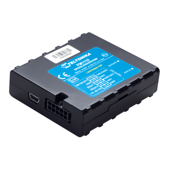
Mini USB socket Storage temperature: -40⁰C ... +70⁰C Storage relative humidity 5 ... 95 % (no condensation) Table 1. FM1110 specifications Figure 1 FM1110 view & dimensions (tolerance ±2mm) When in Deep Sleep mode no data storing and sending is activated. -
Page 10: Electrical Characteristics
Electrical characteristics VALUE Min. Typ. Max. Unit CHARACTERISTIC DESCRIPTION Supply Voltage: Supply Voltage (Recommended Operating Conditions) Digital Output (Open Drain grade): Drain current (Digital Output OFF) Drain current (Digital Output ON, Recommended Operating Conditions) Static Drain-Source resistance (Digital mOhm Output ON) Digital Input: Input resistance (DIN1, DIN2, DIN3) kOhm... -
Page 11: Absolute Maximum Ratings
Note: Analog Input error margin can increase if temperature varies. If Analog input is not connected FM1110 will still measure certain numbers and it cannot be 0. This measurement is influenced by hardware components. Absolute Maximum Ratings VALUE Min. Typ. -
Page 12: Installing Fm1110 Drivers
Remove FM1110 case Insert SIM card as shown Device is ready Attach top housing cover Installing FM1110 drivers Software requirements: • Operating system 32-bit and 64-bit: Windows XP with SP3 or later, Windows Vista, Windows 7. - Page 13 Installing drivers: Extract and run VCPDriver_V1.3.1_Setup.exe. This driver is used to detect FM1110 device connected to the computer. Click 'Next' in driver installation window (figures below): Figure 2 Driver installation window This will launch device driver installation wizard. In the following window click ‘Next’...
-
Page 14: Navigate Led
Navigate LED Behaviour Meaning Permanently switched on GPS signal is not received Blinking every second Normal mode, GPS is working GPS is turned off because: Deep sleep mode GPS module is turned off Status LED Behaviour Meaning Blinking every second Normal mode Blinking every 2 seconds Deep sleep mode... -
Page 15: Usb
Table 2. Socket 2x5 pinout description Mini USB connector Figure 6 Mini USB type B connector FM1110 connected to PC creates an STM Virtual COM Port, which can be used as a system port (to flash firmware and configure the device): Figure 7 COM-Ports... -
Page 16: Accessories
Note: Teltonika does not provide any additional equipment like panic buttons, door sensors or others. 1 – Wire devices One of the realized features FM1110 is 1-Wire® data protocol, which enables connection of thermometer (DS1820, DS18S20 and DS18B20) and I-Button type: DS1990A (Figures 8 and 9 show FM1110 and 1-wire®... - Page 17 FM1110 Analog input to it (if sensor returns analogue signal proportional to fuel level). Figure 10 shows the connection scheme to the FM1110 and fuel tank sensor. After the connection to the tank fuel level sensor, calibration is needed. Calibration is needed because most fuel tank sensors are not linear.
- Page 18 Figure 12 Inverting relay connection Immobilizer relay When connected as shown below, FM1110 disables engine starter when output is OFF. More details about relays can be found below. Figure 13 Immobilizer relay connection Relays An ordinary automotive relay is used to invert input signal or to immobilize engine starter.
-
Page 19: Firmware
Figure 15 FM1110 firmware updater screen Figure 16 FM1110 firmware updating finished When you see a table like in Figure 16, it means that the firmware is flashed to FM1110 successfully. You may now close the update window and start using your FM1110 device. -
Page 20: Operational Basics
GPS data and I/O information. Module uses GPS receiver to acquire GPS data and is powered with three data acquire methods: time-based, distance-based and angle-based method. Note, that if FM1110 loses connection to GPS satellites, it continues to make records, however coordinate in these records remains the same (last known coordinate). Method’s details are described in section 5.13. -
Page 21: Virtual Odometer
It keeps adding these intervals until it is time to make a record, then FM1110 records its location and adds odometer value, which is equal to the sum of all distances, measured every second. -
Page 22: Trip
DOUT1 is controlled by scenario for user needs, for example buzzer or LED. To save GPRS traffic Green Driving event will be generated (included into sent records) only when FM1110 measured values are higher than those set in configuration, without additional I/O settings. -
Page 23: Geofencing
Auto Geofencing feature if enabled is activated automatically by turning off car ignition. Next time before driving user has to disable Auto Geofencing with iButton or by turning on car ignition. In case of theft car leaves Auto Geofencing zone without authorization FM1110 device automatically sends high priority record to AVL application. -
Page 24: Configuration
FM1110 has one user editable profile, which can be loaded from device, and saved. User can also revert to default settings, by pressing Load Defaults button. After any modification of configuration settings it has to be saved to FM1110 device, otherwise it will not be written to device. - Page 25 FM1110 is more configurable. Figure 18 Advanced Configuration window FM1110 Configurator is divided into main areas: 1 – main button area, 2 – information area, 3 –settings menu, 4 – parameters and values menu, 5 – recommended configuration values.
-
Page 26: Record Storage
Record storage FM1110 can store up to 8000 data records if GSM or GPRS is not available at the moment. It will send data later when GPRS is available again. Note that FM1110 can have memory full of records. -
Page 27: System Settings
(lower range gives higher accuracy of measurements), and input voltage; Object Motion Detection Settings, where user can configure 3 ways how FM1110 will detect stopped movement, and change its working mode (for working modes, read section 5.13);... -
Page 28: Records Settings
Figure 19 System settings configuration Records settings Here user can modify if FM1110 device will send newest records first, meaning, that the most important thing is to know recent position of car, older records are being sent right after newest records arrive to AVL application. -
Page 29: Gsm Settings, Sms Part
Essential fields in ‘SMS’ part are ‘Login’ and ‘Password’. The login and password are used with every SMS sent to FM1110. If login and password are not set, in every SMS sent to FM1110 device two spaces before command have to be used (<space><space><command>). -
Page 30: Gsm Settings, Operator List
Figure 23 Operator list configuration If operator list is left empty, it will allow using GPRS to any GSM operator. Please note that FM1110 will work in Unknown mode only (make sure it is configured to allow data sending – GPRS context is enabled). - Page 31 This functionality allows having different AVL records acquire and send parameters values when object is moving or stands still. Vehicle moving or stop state is defined by Stop Detection Source parameter. There are 3 ways for FM1110 to switch between Vehicle on Stop and Vehicle Moving modes see section 5.7.
- Page 32 New GPRS context is opened if time is 10 minutes till time checked in table. Therefore if all boxes are checked, FM1110 is able to open new connection anytime. At scheduled time match FM1110 checks for GPRS session...
- Page 33 Distance based acquire interval. If so, saves the record to memory. If not and speed is higher than 10km/h, then FM1110 checks if angle difference between last record and current record is equal or higher than Angle based acquire value.
-
Page 34: Features Settings
Distance based data acquiring (Min. distance) – records are being acquired when the distance between previous coordinate and current position is greater than defined parameter value. Entering zero disables data acquisition depending on distance. Min. distance Angle based data acquiring (Min. angle) – records are being acquired when angle difference between last recorded coordinate and current position is greater than defined value. - Page 35 Figure 28 Scenarios configuration Digital Output (open drain grade) usage in scenarios: Green Driving DOUT1 is ON for: 3sec. if detected value is over (0; 30] % from preconfigured allowed value 5sec. if detected value is over (30; 50] % from preconfigured allowed value ...
-
Page 36: Trip Settings
5.14.2 Trip settings Trip window offers user to configure Trip feature. If Trip is enabled configuration of parameters are enabled. Start Speed – GPS speed has to be greater than the specified Start Speed in order to detect Trip Start. Ignition Off Timeout –... -
Page 37: Geofencing Settings
5.14.3 Geofencing settings FM1110 has 5 configurable Geofence zones and it can generate an event when defined Geofence zone border is crossed. Frame border – frame border is an additional border around Geofence zone. It is additional area around defined zone used to prevent false event recording when object stops on the border of the area and because of GPS errors some records are made inside area and some –... - Page 38 If vehicle stopped and activation timeout has passed, an AutoGeofence will be created around vehicle’s last position with set Radius value. AutoGeofence event generation works the same as Geofencing mentioned above. Figure 33 Geofence configuration Note: FM1110 operates GMT:0 time without daylight saving.
-
Page 39: Sms Events
The sent SMS messages format is according to: “Date Time EventText” For example, if FM1110 is configured to send an SMS, when Digital Input 1 reaches High level, with priority High and configured to generate event on both range enter and exit (figure 35), then the sent SMS is: “2012/6/7 12:00:00 Digital Input 1”... -
Page 40: Sms Events Configuration
(numbers, letters and symbols in ASCII, except for comma “,”). ATTENTION! If FM1110 is in Deep Sleep mode and SMS event occurs with LOW priority (which does not wake up FM1110), then the device does not send the message. - Page 41 Figure 36 Scenarios SMS event configuration When any of the scenarios events occurs, a text message will be sent to the predefined number. Trip In order to configure Trip SMS events click on Trip window. After enabling SMS Events (figure 37), trip event will be triggered and message sent, when Trip starts (GPS speed exceeds the speed in Start Speed (ex.
- Page 42 Figure 39 AutoGeofence SMS event configuration I/O events FM1110 sends SMS event message when a configured I/O property enters and/or exits its configured High/Low boundaries or Hysteresis event generation is chosen (Monitoring does not generate event, so SMS event could not be configured). Every IO element SMS event can be...
-
Page 43: I/Osettings
Figure 40 I/O SMS event configuration 5.15 I/O settings When no I/O element is enabled, AVL packet comes with GPS information only. After enabling I/O element(s) AVL packet along with GPS information contains current value(s) of enabled I/O element. - Page 44 Permanent I/O elements (are always sent to server if enabled) Property Name Bytes Description Digital Input Status 1 Logic: 0 / 1 Digital Input Status 2 Logic: 0 / 1 Digital Input Status 3 Logic: 0 / 1 Analog Input 1 Voltage: mV, 0 –...
- Page 45 Figure 41 I/O settings Enabled or disabled field – allows enabling I/O element so it is added to the data packet and is sent to the server. By default all I/O element are disabled and FM1110 records only GPS coordinates.
-
Page 46: Monitoring
for Averaging constant time. 1 Averaging constant value equals about 30 miliseconds. In Deep Sleep mode there is no Averaging. Note: I/O element’s “Movement sensor” Averaging constant is interpreted as Start Move Timeout in seconds (from 1 to 59). Start Move Timeout – is a time interval required for movement sensor to be in the moving state, to consider vehicle as moving. -
Page 47: Hysteresis
Figure 45 Event generation according hysteresis algorithm 6 SMS COMMAND LIST Read chapter 5.11 to know how to construct a proper SMS message and send it to FM1110 device. All commands are case sensitive. While FM1110 operates in Deep Sleep mode and user tries to send SMS message it cannot arrive to FM1110 device, because GSM/GPRS module is disabled most of the time (wake up depends on Send Period parameter). -
Page 48: Getstatus
deleterecords Delete all records saved on FLASH getio Readout digital inputs and outputs readio # Readout input value according entered ID, # - ID value setdigout ## Y1 Y2 set digital outputs 0 – OFF, 1 – ON Y1 – timeout for DO1 Y2 –... -
Page 49: Getweektime
6.1.2 getweektime Response details Description Clock Sync Indicates system clock synchronization status. 0 – System is not synchronized, 1 – System synchronized Day Of Week – indicates current day of week starting from 1 – Monday, 2 – Tuesday, etc. Time Indicates current GMT time WeekTime... -
Page 50: Getinfo
Modem App Ver Version of modem application (veiks: nuo 00.05.14) Revision Firmware revision Example: Code Ver:01.06.15 Rev:1 Device IMEI:353976010139156 Device ID:000001 Bootloader Ver: 01.09 Modem APP Ver:TM11Q_R_01.00.03.03_002 6.1.7 getinfo Response details Description Device Initialization Time RTC Time Restart Counter Error Counter Number of Sent Records Number of broken records Profile CRC Fail counter... -
Page 51: Setdigout ## Y1 Y2
Example: I/O ID:3 Value:0 6.1.10 setdigout ## Y1 Y2 Sets digital outputs to ON or OFF state (for some time if needed). Value is written as a row for OUT1 and OUT2 values. Example: ‘setdigout 01 0 5’ will set OUT2 to high level for 5 seconds, while OUT1 to low level. -
Page 52: Banlist
Example if unexpected reset was detected: “Crash: 3051,3052,3053”. 7 Debug mode FM1110 is able to transmit its current state when connected to PC using USB cable. It is used to detect errors and provide information to possible solutions when operating as unexpected. -
Page 53: Parameter List
(value 1) module reduces level of power usage by turning GPS module to sleep, in deep sleep mode (value 2) module turns GPS module to sleep and switch GSM module off (note, that FM1110 do not receive SMS while in deep sleep). Minimum... -
Page 54: Analog Input Value Range (Id=1001)
8.2.5 Static Navigation (ID=1003) When static navigation is enabled, FM1110 filters out GPS jumps, when it is not moving. When it is disabled, it does not make any changes to collected GPS data. Minimum Maximum Recommended Goes with (depends on) -
Page 55: Gnss System (Id=202)
8.2.8 GNSS System (ID=202) This parameter sets Satellite System, available values: 0 - GNSS (all available); 1 – GPS only; 2 – GLONASS only. Minimum Maximum Recommended Goes with (depends on) Value value value value parameters type Records parameters 8.3.1 Sorting (ID=1010) Record sorting parameter is responsible for record sorting order. -
Page 56: Gsm Parameters
GSM parameters 8.4.1 GPRS content ac ivation (ID=1110) Parameter allows or does not allow GPRS usage. If GPRS is not allowed value is 0, if GPRS is allowed value is 1. Minimum Maximum Recommended Goes with (depends on) Value value value value parameters... -
Page 57: Target Server Port (Id=1116)
8.4.6 Target Server Port (ID=1116) Parameter defines AVL data destination server port number. Example: 12050 Minimum Maximum Recommended Goes with (depends on) Value value value value parameters type GPRS content activation Empty 65535 (ID=1110) Target Server Port (ID=1116) 8.4.7 Protocol (ID=1117) Parameter defines GPRS data transport protocol. -
Page 58: Authorized Phone Numbers (Id=1130-1139)
8.4.12 Authorized phone numbers (ID=1130-1139) If at least one number is entered then only those number can send messages to device. Number must be entered without “+” or “00”. Example: 37060012346 Minimum Maximum Recommended Goes with (depends on) Value value value value parameters... -
Page 59: Min Saved Records (Id=1543)
8.5.1.2 Min Saved Records (ID=1543) This parameter defines minimum number of records in one data packet that can be sent to server. It has higher priority than Data Send Period (ID=1544). Minimum Maximum Recommended Goes with (depends on) Value value value value parameters... -
Page 60: Min Distance (Id=1551)
8.5.2.2 Min Distance (ID=1551) This parameter indicates distance in meters in order to acquire new record. Record is stored when the distance between previous records is greater than parameters value. If value is 0 it means no records by min distance will be saved. Minimum Maximum Recommended... -
Page 61: Min Saved Records (Id=1563)
value value value parameters type 2592000 8.5.3.2 Min Saved Records (ID=1563) This parameter defines minimum number of records in one data packet that can be sent to server. It has higher priority than Data Send Period (ID=1564). Minimum Maximum Recommended Goes with (depends on) Value value... -
Page 62: Min Saved Records (Id=1573)
value value value parameters type Min Period (ID=1570) Min Angle (ID=1572) GPRS Week Time (ID=1575) 8.5.4.4 Min Saved Records (ID=1573) This parameter defines minimum number of records in one data packet that can be sent to server. It has higher priority than Data Send Period (ID=1574). Minimum Maximum Recommended... -
Page 63: Gprs Week Time (Id=1585)
value value value parameters type Min Saved Records (ID=1583) 2592000 GPRS Week Time (ID=1585) 8.5.5.4 GPRS Week Time (ID=1585) Read chapter 8.5.1.4. 8.5.6 Unknown Network GSM operator code “Vehicle MOVING” parameters 8.5.6.1 Min Period (ID=1590) This parameter indicates time interval in seconds in order to acquire new record. If value is 0 it means no records by min period will be saved. -
Page 64: Send Period (Id=1594)
8.5.6.5 Send Period (ID=1594) This parameter indicates frequency (time interval in seconds) of sending data to server. In order to send data to server GPRS parameters must be enabled Minimum Maximum Recommended Goes with (depends on) Value value value value parameters type Min Saved Records (ID=1593) -
Page 65: Max Allowed Speed (Id=1605)
scenarios (ID=1600) 8.6.4 Max allowed Speed (ID=1605) It is max allowed speed which can be reached. If this value exceeded Over speeding event will occur. Minimum Maximum Recommended Goes with (depends on) Value value value value parameters type Digital Output No.1 usage scenarios (ID=1600) 8.6.5 Digital Output No.2 usage scenarios (ID=1601) -
Page 66: Geofencing
I/O#11 – Odometer (ID = 1410- 1415) 8.6.10 Geofencing In this chapter it is explained how to get all parameters for the first Geofence zone (all ID numbers are for the 1 zone). And at the end of the chapter (part 8.6.10) is presented a table with the IDs of all the rest Geofence zones. -
Page 67: Geofence Zone #1 Latitude (Y1) (Id=1034)
value value value parameters type -180 Float All Geofencing parameters 8.6.10.6 Geofence Zone #1 Latitude (Y1) (ID=1034) Parameter has two meanings dependent on zone shape. If shape is a rectangle, then ID=1034 is left down corner Y coordinate. If shape is a circle, then ID=1034 is center of that circle Y coordinate. -
Page 68: Activation Timeout (Id=1102)
8.6.11.2 Activation Timeout (ID=1102) Parameter represents AutoGeofencing activation timeout in seconds. Minimum Maximum Recommended Goes with (depends on) Value value value value parameters type 65535 Enable/Disable (ID=1101) 8.6.11.3 Deactivate by (ID=1100) Parameter defines Autogeofence deactivation source. Value 1 is dedicated for attached iButton, value 0 –... -
Page 69: I/Oparameters
I/O parameters I/O properties are additional data sources which are recorded along with usual GPS data. 8.7.1 I/O#1 property parameter (ID=1160) Parameter defines I/O property value. Possible values: enabled (1), disabled (0). Minimum Maximum Recommended Goes with (depends on) Value value value value... -
Page 70: I/O#1 Logic Operand (Id=1164)
Minimum Maximum Recommended Goes with (depends on) Value value value value parameters type I/O#1 property parameter (ID=1160) priority (ID=1161) I/O#1 -2147483647 2147483647 I/O#1 High level (ID=1162) I/O#1 logic operand (ID=1164) I/O#1 averaging length (ID=1165) 8.7.5 I/O#1 logic operand (ID=1164) Parameter defines when event is sent: 0 – on range exit, 1 – on range entrance, 2 – both, 3 –... - Page 71 I/O element I/O Element Number parameters I/O#0 – Digital input 1 1160 – 1165 I/O#1 – Digital input 2 1170 – 1175 I/O#2 – Digital input 3 1180 – 1185 I/O#3 – Analog input 1190 – 1195 I/O#4 – Digital output 1 1200 –...
-
Page 72: Sms Event Configuration
SMS event configuration 8.8.1 I/O#1 element SMS event configuration (ID=100) Command sets SMS warning on I/O#1 element. SMS Format: setparam X Y,W,Z X – ID Y – Enable/Disable (1/0) W – Telephone number INDEX (See 8.4.18 SMS Event Predefined Numbers paragraph, ID 150 –... - Page 73 Reserved 1 Reserved 2 Reserved 3 Reserved 4 Green Driving OverSpeeding Authorized Driving Immobilizer Trip Geo Zone 1 Geo Zone 2 Geo Zone 3 Geo Zone 4 Geo Zone 5 Auto Geofence...
-
Page 74: Mounting Recommendations
These points in the car are the battery terminals. Therefore, we recommend connecting the power of FM1110 (wire GND and POWER) directly to the battery terminals. Another valid option is to connect the wires to the main POWER cable inside the fuse box (if there is none, then to the power supply where the fuses of vehicle’s computer... -
Page 75: Module Installation
SIM card should be inserted in the module while the connector is plugged off (while module has no power). It is recommended to place FM1110 device behind dashboard as close to the window as possible. A good example of device placement is displayed in a picture below. -
Page 76: Change Log
10 CHANGE LOG Date Version Comments 2014-03-19 Preliminary draft release. 2014-03-26 Changed pictures. 2014-04-09 Changed software download links. 2014-04-22 Added new IO id’s. 2014-05-22 Added IO elements 21-28 SMS configuration IDs; Edited SMS Events configuration table. 2014-06-04 Change pic. Immobilizer relay connection. 2014-07-01 Added GNSS Settings parameter.
Need help?
Do you have a question about the FM1110 and is the answer not in the manual?
Questions and answers