Table of Contents
Advertisement
Quick Links
Oracle Talari E1000 Installation Guide
Purpose
This guide will help you set up your E1000 using typical
deployment scenarios.
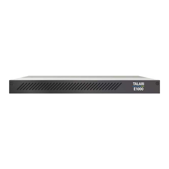
E1000 Overview
The E1000 is an extension of the E-series of Oracle Talari
Appliances and intended for use in large branch or regional
offices that require higher performance and port density than the
E100 provides. The E1000 supports all major Talari Adaptive
Private Network (APN) features, including Service Chaining, and
WAN Optimization.
IMPORTANT :
Your E1000 ships with a piece of foam behind the
faceplate to prevent damage during shipping. The
foam must be removed before powering on the
appliance to avoid overheating the device.
(Please refer to the Unpacking and Inspection
Checklist for instructions.)
Version 1.1
Quick Reference
E1000 Hardware Options ........................................................
What's Included .......................................................................
E1000 Front Panel ...................................................................
E1000 Back Panel ...................................................................
E1000: No Expansion Card ..................................................
E1000: 10G Fiber (2 Port) Expansion Card ..........................
Unpacking and Inspection Checklist ........................................
Rack Mounting ........................................................................
4-Post Rack Mounting (Recommended) ...............................
2-Post Rack Mounting .........................................................
Network Deployment Options.................................................
E1000 as a Router (Gateway, Fail to Block) ........................
E1000 as Layer 2 Fail-To-Wire (Overlay) ............................
E1000 with MPLS & Internet Hybrid ...................................
Installation Options .................................................................
Easy 1st Install .....................................................................
Manual Install .......................................................................
2
4
5
5
5
6
7
8
8
8
12
14
14
14
14
15
15
19
\
1
Advertisement
Table of Contents

Related Manuals for Oracle Talari E1000


Summary of Contents for Oracle Talari E1000
-
Page 1: Table Of Contents
E1000: 10G Fiber (2 Port) Expansion Card ......E1000: Fail to Wire Copper (4 Port) Expansion Card ... Unpacking and Inspection Checklist ........The E1000 is an extension of the E-series of Oracle Talari Rack Mounting ................ Appliances and intended for use in large branch or regional 4-Post Rack Mounting (Recommended) ....... -
Page 2: E1000 Hardware Options
E1000 Hardware Options To best meet the needs of Talari customers worldwide, the E1000 appliance allows for three different hardware Related Publications ordering options: The following documents are available: E1000 (with No Expansion Card) Talari APN 7.0 New Features Guide ... - Page 3 The information contained herein is subject to change without notice and is and Oracle. Oracle Corporation and its affiliates will not be responsible for not warranted to be error-free. If you find any errors, please report them to any loss, costs, or damages incurred due to your access to or use of third- us in writing.
- Page 4 Acrobat Reader, which can be downloaded at http://www.adobe.com. registration and opening a support ticket. 1. Access the Oracle Help Center site at http://docs.oracle.com. My Oracle Support is available 24 hours a day, 7 days a week, 365 days a year. 2. Click Industries. Emergency Response 3.
-
Page 5: What's Included
What’s Included 1x Blue Management Cable 2x Green LAN Cables 1x Red Crossover Cable 2x Orange WAN Cables 2x Front Outer Rails 1x Console Cable 1x Power Cord 2x Back Outer Rails 2x Pre-Threaded (10-32) 2x Non-Threaded Brackets for 2-Post Racks Brackets for 2-Post Racks 2x Inner Expansion Rails (Optional) -
Page 6: E1000 Front Panel
E1000 Back Panel The Talari E1000 may be ordered with three different hardware options. Installation will vary based on which E1000 hardware option is being deployed. Each E1000 hardware option can be visually identified by comparing the back of the appliance to the E1000 back panel images below. -
Page 7: E1000: 10G Fiber (2 Port) Expansion Card
E1000: 10G Fiber (2 Port) Expansion Card Port 9 Port 10 The E1000: 10G Fiber (2 Port) appliance (shown directly above) is identical to the E1000: No Expansion Card device (shown on page 4) with the addition of the following: Port 9: 10 Gigabit Ethernet (non-bypass) Port 10: 10 Gigabit Ethernet (non-bypass) Note: The E1000 with 10G Fiber (2 Port) appliance does not ship with SFP modules. -
Page 8: E1000: Fail To Wire Copper (4 Port) Expansion Card
E1000: Fail to Wire Copper (4 Port) Expansion Card Port 9 Port 10 Port 11 Port 12 The E1000: Fail to Wire Copper (4 Port) appliance (shown directly above) is identical to the E1000: No Expansion Card appliance (shown on page 4) with the addition of the following: Port 9: Gigabit Ethernet (Bypass pair with Port 10) Port 10: Gigabit Ethernet (Bypass pair with Port 9) Port 11: Gigabit Ethernet (Bypass pair with Port 12) -
Page 9: Unpacking And Inspection Checklist
Unpacking and Inspection Checklist Remove E1000 appliance and accessories from box. Remove E1000 from plastic wrapping. Inspect appliance for signs of damage. Remove foam insert wedged between faceplate and inner front of appliance by using thumbscrews on front of appliance to loosen faceplate. - Page 10 Layout & Required Components: 2x Front Outer Rails 2x Back Outer Rails 2x Inner Expansion Rails (optional; inner expansion rails allow the chassis to be pulled out further when rack mounted for enhanced serviceability) Rail Assembly 1. Place the rails with the arrows indicating front and back of the device in the correct direction. Note: For both front and back rails for the E1000 it is important to ensure that they are pointing in the correct orientation (Front or Back) even if the arrows or the text are displayed upside down.
- Page 11 If using the optional Inner Expansion Rails, place the Inner Expansion Rails on the appliance behind the pre-installed inner rails, aligning the holes in the Inner Expansion Rail with the holes in the side of the chassis (circled in blue below). Ensure that the arrow on each Inner Expansion Rail points towards the back of the appliance.
- Page 12 2. Depress the Side Rail Locks (circled in blue below) to allow the device to be unlocked from the rails. Figure 5: Side View of E1000 Showing Side Rail Locks 3. Remove chassis from rails. 4. Once chassis has been removed, rails can be unlocked from the rack by depressing the self-locking arm locks on each end of the outer rails (see Figures 3 and 4, circled in blue).
-
Page 13: 2-Post Rack Mounting
2-Post Rack Mounting Layout & Required Components: 2x Front Outer Rails 2x Pre-Threaded (10-32) Brackets for 2-Post Racks 2x Front Outer Rails 2x Non-Threaded Brackets for 2-Post Racks (For use with your own cage nuts and rack screws) Assembly 5. - Page 14 Installation 7. Facing front of rack, install each assembled Front Outer Rail (with joined bracket) to the two post rack using rack screws (not provided). 8. Slide the E1000 onto the rail arms until you hear the click from the Side Rail Locks on the E1000 indicating proper installation. Removal 9.
-
Page 15: Network Deployment Options
Network Deployment Options Before getting started it is important to determine how the E1000 will be deployed. When considering deployment options for the E1000, please note that all bypass pairs will default to Fail-To-Block until configured otherwise. Example instructions for some of the most common deployment scenarios are provided below: E1000 as a Router (Gateway, Fail to Block) Description: The E1000 is deployed as the WAN gateway for the site, and bypass pairs are configured as Fail-To-Block. -
Page 16: Installation Options
Installation Options Easy 1st Install Important Note: If the Talari configuration for the E1000 does not match the installed hardware (for example, if the appliance is an E1000 with No Expansion Card and an interface between 9 and 12 is configured), the Talari service be disabled when the package is applied, and the appliance will need to be factory defaulted before Easy 1 Install can be attempted again. - Page 17 E1000 with 10G Fiber Expansion Card: Port 9 Port 10 Port 9: 10 Gigabit Ethernet (non-bypass) Port 10: 10 Gigabit Ethernet (non-bypass) Note: Ports 9 and 10 should only be configured with Bypass Mode set as Fail-to-Block on an E1000 with 10G Fiber expansion card. The 10G Fiber expansion card does not support Fail-to-Wire, and the Talari service will not start if a configuration specifying Fail-to- Wire for these ports is applied to an E1000 with 10G expansion card.
- Page 18 E1000 with Fail-to-Wire Expansion Card: Port 9 Port 10 Port 11 Port 12 Port 9: Gigabit Ethernet (Bypass pair with Port 10) Port 10: Gigabit Ethernet (Bypass pair with Port 9) Port 11: Gigabit Ethernet (Bypass pair with Port 12) Port 12: Gigabit Ethernet (Bypass pair with Port 11) Note: Ports 9 and 10 may be configured in either Bypass Mode on an E1000 with Fail-to-Wire expansion card, as may ports 11 and 12.
- Page 19 4. Locate the Site name of the E1000 being deployed. 13. Click the Edit pencil to open the Set Serial Number window. 14. Enter the serial number of the E1000 being deployed and click the Set Serial Number button. (Refer to Page 4 for assistance locating the serial number.) 15.
-
Page 20: Manual Install
Manual Install Important Note: If the Talari configuration for the E1000 does not match the installed hardware (for example, if the appliance is an E1000-Base and an interface between 9 and 12 is configured), the Talari service will be disabled when the package is applied. A corrected package will have to be uploaded via Local Change Management (as outlined in steps 4-7 of Deploying the Talari Appliance) to bring up the Talari service. - Page 21 E1000 with 10G Fiber Expansion Card: Port 9 Port 10 Port 9: 10 Gigabit Ethernet (non-bypass) Port 10: 10 Gigabit Ethernet (non-bypass) Note: Ports 9 and 10 should only be configured with Bypass Mode set as Fail-to-Block. The 10G Fiber expansion card does not support Fail-to-Wire, and the Talari service will not start if a configuration specifying Fail-to-Wire for these ports is applied to an E1000 with 10G expansion card.
- Page 22 E1000 with Fail-to-Wire Expansion Card: Port 9 Port 10 Port 11 Port 12 Port 9: Gigabit Ethernet (Bypass pair with Port 10) Port 10: Gigabit Ethernet (Bypass pair with Port 9) Port 11: Gigabit Ethernet (Bypass pair with Port 12) Port 12: Gigabit Ethernet (Bypass pair with Port 11) Note: Ports 9 and 10 may be configured in either Bypass Mode on an E1000 with Fail-to-Wire expansion card, as may ports 11 and 12.
- Page 23 2. Connect your PC directly to the AUX Port of the E1000. 3. From the PC connected to the Talari: a. Change the IP address of your PC to 192.168.0.1. b. Change the Subnet Mask of your PC to 255.255.255.252. c.
- Page 24 Version 1.1...
Need help?
Do you have a question about the Talari E1000 and is the answer not in the manual?
Questions and answers