Table of Contents
Advertisement
Quick Links
Advertisement
Table of Contents

Related Manuals for LeCroy USB Protocol Suite Advisor T3


Summary of Contents for LeCroy USB Protocol Suite Advisor T3
- Page 1 ROTOCOL OLUTIONS ROUP 3385 S COTT , CA 95054 ANTA LARA LeCroy USB Protocol Suite™ User Manual Manual Version 4.21 Advisor T3™ USB Advisor™ USBTracer/Trainer™ Voyager M3™ USBMobile HS USBMobile T2 For Software Version 4.21 June 2011...
- Page 2 LeCroy could result in the product not meeting the Class A limits, in which case the FCC could void the user's authority to operate the equipment.
- Page 3 Many countries prohibit the disposal of waste electronic equipment in standard waste receptacles. For more information about proper disposal and recycling of your LeCroy product, please visit www.lecroy.com/recycle. LeCroy Corporation...
- Page 4 USB Protocol Suite User Manual LeCroy Corporation...
-
Page 5: Table Of Contents
2.7.2 Back Panel ........34 2.8 USBTracer System Setup ......35 LeCroy Corporation... - Page 6 3.5.5 USB 3.0 Device/Host Signal Parameters ....62 3.5.6 USB 3.0 Cabling and Signal Integrity ....64 LeCroy Corporation...
- Page 7 5.6 View Raw Bits (2.0) ........100 LeCroy Corporation...
- Page 8 5.45 Edit Comment........124 viii LeCroy Corporation...
- Page 9 7.4 USB 3.0 Packet Hiding Options ......152 7.5 Saving Display Options ....... 153 LeCroy Corporation...
- Page 10 9.13.1 Power Tracker Toolbar ......211 9.14 Running Verification Scripts ......212 LeCroy Corporation...
- Page 11 10.5.11 Using a Multi-State Sequences ....262 10.5.12 Using Independent Sequences....262 LeCroy Corporation...
- Page 12 12.3 Exerciser Files ........309 12.4 Creating Exerciser Files ......309 LeCroy Corporation...
- Page 13 13.6 Registering Online ........352 xiii LeCroy Corporation...
- Page 14 Table ....... 353 How to Contact LeCroy ......355 Limited Hardware Warranty .
-
Page 15: Chapter 1 Overview
You can name and save display formats for later use. Pop-up tooltips annotate packet fields. The display software operates independently of the hardware, allowing it to function as a stand-alone “trace viewer” that you can freely distribute. Figure 1.1 Trace Viewer LeCroy Corporation... -
Page 16: Accurate Time Measurement (Voyager, Advisor T3)
LeCroy software. Search, reporting, and decoding all operate normally. This feature is available with the LeCroy USB Protocol Suite application. 1.1.4 Comprehensive Error Detection and Analysis The system detects, and alerts you to, every potential bus error and protocol violation, and their combinations. -
Page 17: Real-Time Event Triggering And Capture Filtering
1.1.7 BusEngine Technology The Analyzer uses LeCroy BusEngine Technology. The BusEngine core uses Electrically Programmable Logic Device (EPLD) technology and incorporates both a real-time recording engine and configurable building blocks that implement data/state/error detection, triggering, capture filtering, external signal monitoring, and event counting and sequencing. -
Page 18: Voyager M3 Analyzer
USB Protocol Suite User Manual 1.2 Voyager M3 Analyzer The LeCroy Voyager M3™ Analyzer and Exerciser system is a multifunction verification system for USB 2.0 and USB 3.0 development and testing. It can record traffic and graphically present logical USB transactions and events. It can also generate USB traffic. - Page 19 If configured for USB 3.0 testing, the system supports monitoring between SuperSpeed links using USB 3.0 cables (Figure 1.3) Figure 1.3 Direct Connection using USB 3.0 Cables or through direct connection via MMCx-to-SMA coaxial cables (Figure 1.4). Figure 1.4 Direct Connection using SMA Differential Tap LeCroy Corporation...
-
Page 20: Voyager M3 General Description
Please refer to the Universal Serial Bus Specification for details on the protocol. The USB specification is available from the USB Implementers Forum (USB-IF) at: USB Implementers Forum Tel: +1/503.296.9892 1730 SW Skyline Blvd. Fax: +1/503.297.1090 Suite 203 Web: http://www.usb.org/ Portland, OR 97221 LeCroy Corporation... -
Page 21: Voyager M3 Features
USB 2.0 Hi-Speed connection to desktop or portable host PC • Internal wide-range AC power supply • Expansion port for future enhancements • SMA connectors and USB 3.0 connectors for SuperSpeed capture and generation • External clock inputs and outputs LeCroy Corporation... - Page 22 Token, Bus Conditions, Data Length, and excessive empty frames (2.0) • Real-time traffic capture filtering and data packet truncation variable up to 256 bytes (2.0) • Adjustable buffer size from 0.4 MB to 1 GB or 4 GB • Idle filtering (3.0) LeCroy Corporation...
-
Page 23: Hi-Speed Slow Clock
Uses a Spec View to show packets in the same format as the USB 3.0 specification (3.0). • Has Quick Timing Markers to immediately show time deltas and bandwidth use. 1.2.3 Hi-Speed Slow Clock • Trace and generate High-Speed traffic at fractional (slow) clock rate capability (2.0) LeCroy Corporation... -
Page 24: Traffic Generation
When NAKs are received, the Exerciser can automatically resend the previous packet. Voyager ReadyLink™ Emulation The LeCroy Voyager USB 3.0 Exerciser features ReadyLink Emulation Mode. The ReadyLink feature handles all USB 3.0 link training and link flow control, allowing the emulator to operate at full line rate and respond to the DUT as defined by the specification. -
Page 25: Notes On Lfps Signals
Voyager Exerciser requires received “Ping” LFPS signals to be a minimum of 150 nanoseconds to be reliably recognized. Voyager Analyzer can recognize “Ping” LFPS signals above 60 nanoseconds and report ± their durations to 15 nanoseconds of accuracy. LeCroy Corporation... -
Page 26: Usbtracer/Trainer
1.3 USBTracer/Trainer The LeCroy USBTracer™ USB 2.0 Design & Verification System is the fifth generation product of LeCroy's analysis tools for USB development and testing. The USB bus & protocol Analyzer interfaces with standard USB cables and connections to capture and display all speeds of USB 2.0 bus traffic. - Page 27 USB Protocol Suite User Manual Chapter 1: Overview The Analyzer is a plug-in module that installs into a LeCroy Universal Protocol Analyzer System (UPAS). Together, the Analyzer and UPAS are controlled from a personal computer USB port across a USB connection.
-
Page 28: Usbtracer/Trainer Features
Self-diagnoses at power on. • Has a 36-month warranty and hot-line customer support. • Works in conjunction with the LeCroy USBTrainer USB Traffic Generator hardware module to create a fully customizable USB test platform. Physical Components • Hardware module for the LeCroy Universal Protocol Analyzer System •... - Page 29 Detects, and alerts you to, every potential bus error and protocol violation, and their combinations. • Has high-resolution, accurate time stamping of bus packets and timing measurement and analysis functions. • Has search and packet hiding capabilities. • Allows comprehensive device class decoding and user-defined protocol decoding. LeCroy Corporation...
-
Page 30: Traffic Generation
1.3.4 Hi-Speed Slow Clock The ability to trace and generate Hi-Speed traffic at fractional (slow) clock rate is available on both USBTracer platforms (2500 and 2500H). You can purchase this feature with a License Key. Contact LeCroy for more information. LeCroy Corporation... -
Page 31: Advisor
Chapter 1: Overview 1.4 Advisor The LeCroy Advisor™ USB 2.0 Bus & Protocol Analyzer is a LeCroy fourth-generation product for USB development and testing. The Advisor interfaces with standard USB cables and connections to capture and display Hi-Speed and Classic-Speed USB 2.0 bus traffic. - Page 32 Advanced triggering with event counting and sequencing • Dedicated trigger for recording input and output that is used to interface to external test equipment • Real-time traffic capture filtering and data packet truncation variable up to 245 bytes LeCroy Corporation...
- Page 33 Has high-resolution, accurate time stamping of bus packets and timing measurement and analysis functions. • Has search and packet hiding capabilities. • Allows comprehensive device class decoding and user-defined protocol decoding. Refer to Readme.txt on your installation CD for the latest information on features. LeCroy Corporation...
-
Page 34: Advisor T3
USB Protocol Suite User Manual 1.5 Advisor T3 The LeCroy USB Advisor T3™ USB 3.0 Protocol Analyzer is a verification system for USB development and testing. It supports both USB 2.0 and USB 3.0. It can record USB traffic and graphically present the logical transactions and events. It connects to a laptop or desktop PC through its USB port. -
Page 35: Advisor T3 General Description
Please refer to the Universal Serial Bus Specification for details on the protocol. The USB specification is available from the USB Implementers Forum (USB-IF) at: USB Implementers Forum Tel: +1/503.296.9892 1730 SW Skyline Blvd. Fax: +1/503.297.1090 Suite 203 Web: http://www.usb.org/ Portland, OR 97221 LeCroy Corporation... -
Page 36: Advisor T3 Features
USB 2.0 Hi-Speed connection to desktop or portable host PC • DC power supply • Expansion port for optional External Trigger In/Out cable, as well as multi-box synchronized recording • USB 3.0 connectors for SuperSpeed capture and generation LeCroy Corporation... - Page 37 Token, Bus Conditions, Data Length, and excessive empty frames (2.0) • Real-time traffic capture filtering and data packet truncation variable up to 256 bytes (2.0) • Adjustable buffer size from 0.4 MB to 2 GB • Idle filtering (3.0) LeCroy Corporation...
- Page 38 Uses Link Tracker to view symbols of traffic (3.0). • Has a Spec View to show packets in the same format as the USB 3.0 specification (3.0). • Uses Quick Timing Markers to immediately show time deltas and bandwidth use. LeCroy Corporation...
-
Page 39: Usbmobile T2
Chapter 1: Overview 1.6 USBMobile T2 The LeCroy USBMobile T2™ is a portable hardware-based USB 2.0 protocol analyzer that debugs, tests, and verifies low, full, and high-speed USB devices. The USBMobile T2 fits into a single PCMCIA slot in a laptop computer. The USBMobile T2 uses the standard CATC Trace display. -
Page 40: Features
PC Card Design Portable operation with any notebook PC CATC Trace software Speeds interpretation and debug of USB traffic. Compatible with display LeCroy USBMobile™, Inspector™, Chief™, Advisor™, and USBTracer/Trainer™. OTG (On-The-Go) Records and analyzes HNP and SRP, including capture of VBus Support... - Page 41 Detects, and alerts the user to, every potential bus error and protocol violation, and their combinations. • Has high-resolution, accurate time stamping of bus packets and timing measurement and analysis functions. • Has search and packet hiding capabilities. • Allows comprehensive device class decoding and user-defined protocol decoding. LeCroy Corporation...
-
Page 42: Usbmobile Hs
USB Protocol Suite User Manual 1.7 USBMobile HS The LeCroy USBMobile HS™ USB Hi-Speed Analyzer is a portable, PC Card based, bus and protocol analyzer that accurately and efficiently debugs, tests, and verifies Low, Full, and Hi-Speed USB semiconductors, devices, software and systems. -
Page 43: Chapter 2 General Description
2.3 Voyager M3 Analyzer The Analyzer is shown in the figure. Figure 2.1 Voyager M3 Analyzer Front The Analyzer has the following features: Power Switch (0/1) Status LED (blue if system successfully initializes red if hardware failure green while initializing) LeCroy Corporation... - Page 44 Tx + - Transmit pair Rx + - Receive pair Clock A (downstream) - MMCx plug connectors for interfacing Clock B (upstream) with external clock source or sink In - Connects to an external reference clock. Out- Provides reference clock output. LeCroy Corporation...
- Page 45 - Type B connector for connection to host computer ETHERNET- Gigabit Ethernet connector for connection to host computer Note: The rear has only a power connector. Warning: Do not open the Voyager M3 enclosure. No operator serviceable parts are inside. Refer servicing to LeCroy customer care. LeCroy Corporation...
-
Page 46: Voyager M3 Specifications
SuperSpeed connectors USB 3.0 cables MMCx connectors for USB 3.0 High Speed USB Connectors Standard cables 2.4.4 Switches Power On/off 2.4.5 Recording Memory Size 1 GB or 4 GB for traffic data capture, timing, state and other data. LeCroy Corporation... -
Page 47: Usbtracer/Trainer System Components
PC and operating system requirements. 2.7 The Installed USBTracer Unit USBTracer is a module that inserts into the left slot on the LeCroy Universal Protocol Analyzer System (UPAS). Once installed, the USBTracer Analyzer activates the user-accessible controls and LEDs on the front and rear panels of the UPAS. -
Page 48: Led And Button Descriptions
Manual Trigger push-button: Allows a manual Trace capture. LEDs and Button on the UPAS under the Right Module Slot The LEDs and button under the right module slot are reserved for LeCroy generator modules such as the USBTrainer USB Traffic Generator (described in Traffic Generation (2.0) on page 277):... -
Page 49: Usbtracer System Setup
AC power connection External trigger connection Host connection (USB, type B) 2.9.3 Weight UPAS 7.5 lb. (3.4 kg) USBTracer Plug-in 1.0 lb. (0.5 kg) 2.9.4 Power Requirements 90 to 254 VAC, 47 to 63 Hz (universal input), 100 W maximum LeCroy Corporation... -
Page 50: Environmental Conditions
Illuminated when the Analyzer is actively recording traffic data. Triggered (TRG): Illuminated during power-on testing and when the Analyzer has detected a valid trigger condition. Uploading (UPLD): Illuminated when the Analyzer is uploading its recording memory to the Host PC to display the CATC Trace. LeCroy Corporation... -
Page 51: Recording Memory Size
All speeds: Low, Full, and Hi. The Classic model may be upgraded to a Hi-Speed model by purchasing a License Key from LeCroy. Contact your LeCroy representative for more information. Note: The UPAS 2500 and UPAS 2500H products include internal 1.1 and 2.0 Hubs. -
Page 52: Usbtracer/Trainer External Interface Breakout Board
The Breakout Board connects by cable to the Data In/Out connector located on the rear of the Analyzer box. Each signaling pin is isolated by a 100 series resistor and a buffer inside the Analyzer box. Figure 2.5 Data In/Out Connector (on cable) LeCroy Corporation... -
Page 53: Pin-Outs For The Data In/Out Connector
The top row of holes connects to GND, and the bottom row connects to +5 V. The remaining holes are not connected. Use the rework area to insert custom components and wire-wrap their respective signal, power, and ground pins. LeCroy Corporation... -
Page 54: Advisor
USB Protocol Suite User Manual 2.11 Advisor The LeCroy USB Advisor™ USB 2.0 Protocol Analyzer is a stand-alone unit controlled and configured by a portable or desktop PC connected through its USB port. The Advisor uses hardware triggering to capture real-time events and hardware filtering to preserve memory and find data. -
Page 55: Advisor Stand-Alone Unit
Two USB ports, High Speed and Classic Speed, each with a type A and a type B connector. • High Speed: Used to record 480 MB/s High-Speed traffic only • Classic Speeds: Used to record either 12 MB/s or 1.5 MB/s Classic-Speed traffic LeCroy Corporation... - Page 56 Do not use the BNC connector for any purpose! (The Trigger In and Trigger Out functions are only available through the Breakout Board accessory.) Warning! Do not open the Analyzer enclosure. There are no operator serviceable parts inside. Refer servicing to LeCroy. LeCroy Corporation...
-
Page 57: Advisor System Setup
USB port. It can be used with portable computers for field service and maintenance as well as with desktop units in a development environment. To install, connect a cable between the computer’s USB port and the Analyzer’s USB port. Figure 2.8 USB Advisor Connection LeCroy Corporation... -
Page 58: Advisor Specifications
Uploading (UPLD) Illuminated when the Analyzer is uploading its recording memory to the host PC for display 2.16.6 Recording Memory Size 128 megabyte DRAM for traffic data capture, timing, state and other data LeCroy Corporation... -
Page 59: Advisor External Interface Breakout Board
The Breakout Board connects by cable to the Data In/Out connector located on the rear of the Analyzer box. Each signaling pin is isolated by a 100 series resistor and a buffer inside the Analyzer box. Figure 2.10 Data In/Out Connector (on cable) LeCroy Corporation... -
Page 60: Pin-Outs For The Data In/Out Connector
Use the rework area to insert custom components and wire-wrap their respective signal, power, and ground pins. 2.17.3 PC Connection Use the LONGEST (6-foot/2-meter) of the five USB cables provided to connect the host computer to the Analyzer box. LeCroy Corporation... -
Page 61: Advisor T3
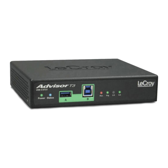
Chapter 2: General Description 2.18 Advisor T3 The LeCroy USB Advisor T3™ USB 3.0 Protocol Analyzer is a verification system for USB development and testing. It supports both USB 2.0 and USB 3.0. It can record USB traffic and graphically present the logical transactions and events. It connects to a laptop or desktop PC via USB 2.0. -
Page 62: Rear Panel
Type B connector for connection to host computer Sync/Data: Micro DB-25 (25-pin) external interface connector (cable sold separately) Power Connector 12V, 3A DC Power Switch (0/1) Do not open the enclosure. No operator serviceable parts are inside. Refer servicing to LeCroy customer care. LeCroy Corporation... -
Page 63: Advisor T3 System Setup
USB Protocol Suite User Manual Chapter 2: General Description 2.18.4 Advisor T3 System Setup Advisor T3 is configured and controlled through a personal computer USB port. Figure 2.13 Advisor T3 Setup LeCroy Corporation... -
Page 64: Usbmobile T2 And Usbmobile Hs
Because poor signal quality in the middle of a USB cable, LeCroy recommends using the shortest possible cables, so that total length of both cables together is less than six feet. The USB cables provided with your Analyzer meet this requirement. -
Page 65: Chapter 3 Installation
At power-on, the Analyzer initializes itself in approximately ten seconds and performs an exhaustive self-diagnostic that lasts about five seconds. If the diagnostics fail, call LeCroy Customer Support for assistance. Step 5 Click Next after you see the Add New Hardware Wizard window. -
Page 66: Setting Up The Analyzer - Ethernet Connection
At power-on, the Analyzer initializes itself in approximately ten seconds and performs an exhaustive self-diagnostic that lasts about five seconds. If the diagnostics fail, call LeCroy. Step 5 Complete Analyzer setup in the “Application Startup” section (See “Application Startup” on page 56). -
Page 67: Cascading With Catc Sync Expansion Card
OR two Advisor T3s. You cannot use one of each. Also, you must enable 3.0 Auto-Detect/Termination mode. Manual control does not work. 3.4.1 Removing Expansion Cards You can remove expansion cards using two tools: • Standard (flat blade) 3/16” screwdriver • LeCroy Extraction Tool (part number 230-0160-00) LeCroy Corporation... - Page 68 Note: If the prongs do not slip easily into the holes, use a small nail file or similar device to remove paint from the prongs. Step 3 Rotate the extraction tool to a horizontal position to lock the prongs into place and make a handle. LeCroy Corporation...
- Page 69 Step 5 Using the extraction tool as a handle, gently wriggle the expansion card forward about 1/8”. Step 6 Repeat steps 4 and 5 approximately three times, until the card is free from the retaining screws and you can remove the card from the system. LeCroy Corporation...
-
Page 70: Application Startup
Chapter 3: Installation USB Protocol Suite User Manual 3.5 Application Startup To start the application, launch the LeCroy USB Protocol Suite program from the Start Menu: Start > Programs > LeCroy > USB Protocol Suite > USB Protocol Suite to open the main window. -
Page 71: Analyzer Devices
IP Address. • IP Settings to use a DHCP or Static IP address. To refresh the list of devices, click Refresh Device List. Before starting recording, select the Analyzer you want to use for recording. LeCroy Corporation... -
Page 72: Ip Settings (Voyager Only)
To change from DHCP to Static IP while connected to a device: Step 1 Select Setup > All Connected Devices from the menu bar to display the Analyzer Devices dialog. Note: If you are not connected to a device, the IP Settings command is grayed out. LeCroy Corporation... - Page 73 Step 2 Select the device to use in the recording, then click the IP Settings button to display the Device IP Settings dialog. Two radio buttons are available: • Obtain IP address automatically (DHCP) [default] • Use the following IP Address (Static IP) LeCroy Corporation...
- Page 74 Click Apply to get a success message and return to the Analyzer Devices dialog. Note: You can let the system Suggest static IP settings (IP address and subnet mask). Step 4 Click Close to close the dialog and use the device with a Static IP address. LeCroy Corporation...
-
Page 75: Analyzer Network
The dialog displays the computers on the network and the Analyzer devices connected to the computers. You can click Add to display the Add Analyzer Network Node dialog, in which you can select a computer on the network You can also Remove a selected computer or Reconnect a selected computer. LeCroy Corporation... -
Page 76: Usb 3.0 Device/Host Signal Parameters
USB3 Device -> Analyzer -> Host Signal Profiles dialog. The dialog lists the Device Name, Device Cable, Host Name, Host Cable, and to what the Profile Signal Settings apply. It also shows Device-to-Analyzer and Host-to-Analyzer custom signal settings. LeCroy Corporation... - Page 77 Pre-Emphasis Settings: Short and long time level (0 to 15) and short and long time decay (0 to 7) • Output Power Level: Current, or 213 mV to 1294 mV You can also Load the default settings or Load the last applied settings. LeCroy Corporation...
-
Page 78: Usb 3.0 Cabling And Signal Integrity
Do not "stress" the system by using long or low-quality cabling that might result in signal degradation. If you suspect signal integrity problems in capture situations, you should first try using shorter and higher-quality cables to see if this rectifies the problem. LeCroy Corporation... -
Page 79: Your First Usb Recording
Items not supported on your hardware are grayed out or not shown. Step 4 Click OK to activate the recording options you selected. Step 5 Turn on the USB devices that are to be tested and cause them to generate USB traffic. LeCroy Corporation... - Page 80 Step 8 To save a current recording for future reference, select File > Save As on the Menu Bar. Click on the Tool Bar to display the standard Save As window. Give the recording a unique name and save it to the appropriate directory. LeCroy Corporation...
-
Page 81: Trace View Features
The display software can operate independently of the Analyzer. When used without the Analyzer, the program functions in a Trace Viewer mode to view, analyze, and print captured protocol traffic. When used with the Analyzer, you can set trigger conditions, record, monitor, and analyze the activity of your USB bus. LeCroy Corporation... -
Page 82: Notes On Vista And Windows 7 Directory Protections
Program Files directory/folder. It was common for applications written for Windows XP (and earlier) to use the Program Files folder to store user data. LeCroy and CATC products used this folder as a default folder for storing trace files, user option files (default.opt, default.rec), scripts, and so on. -
Page 83: Chapter 4 Software Overview
USB branch from USB ports on the Analyzer front. 4.1 Starting the Program To start the USB Protocol Suite application: Step 1 Select Start > Programs > LeCroy > USB Protocol Suite > USB Protocol Suite. LeCroy Corporation... -
Page 84: The Main Display Window
OUT/IN is identical to the data IN/OUT from the other endpoint. Used when running echo-types of tests for data integrity. Available only when a trace file (.usb) is open. (2.0 only) Exit Exits the program. LeCroy Corporation... - Page 85 Stop and lets you stop traffic generation. IntelliFrame Sets the mode of generation to IntelliFrame. Use before Start. Generation Mode (2.0 only) Bitstream Generation Sets the mode of generation to bitstream. Use before Start. Mode (2.0 only) LeCroy Corporation...
- Page 86 See “USB3 LTSSM View” on page 209. Power Tracker Displays voltage, current, and power. See “Power Tracker” on page 210. Run Verification Opens a window to allow you to run verification scripts over the Scripts open trace. See “Running Verification Scripts” on page 212. LeCroy Corporation...
- Page 87 Increases the size of the displayed elements. Zoom Out Decreases the size of the displayed elements. Wrap Wraps displayed packets within the window. Show USB 2 Traffic Displays only USB 2.0 traffic. Only Show USB 3 Traffic Displays only USB 3.0 traffic. Only LeCroy Corporation...
- Page 88 DWA Segment Level displays Device Wire Adapter Segments. DWA Transfer Level displays Device Wire Adapter Transfers. PTP Group PTP Transaction Level displays PTP Transactions PTP Object Transfer Level displays PTP Objects PTP Session Level displays PTP Sessions SCSI Operation Level Displays SCSI Operation Level LeCroy Corporation...
- Page 89 Check for Updates Use the Internet to analyze your system for licensed updates. You can set the system to automatically check for updates at application startup in the LeCroy USB Protocol Suite Software Update window. See “Software Updates” on page 346. About...
-
Page 90: Exports To .Csv
When viewing 2.0 Packets in either the Black and White or Colored Spreadsheet Views Trace view, selecting Export > Spreadsheet to .CSV exports the contents of the spreadsheet to a .csv file in a pre-configured format. The columns match the columns as you have defined them in your Spreadsheet view. LeCroy Corporation... -
Page 91: Exporting To Usb 2.0 Generation Files (.Utg Files)
SOF packets in the .utg file. This is required because, when the capture is made in Auto-Speed Detect mode, the first "Ping" sequence is not captured in the trace file. LeCroy Corporation... -
Page 92: Tool Bar
Find (see “Find” on page 138) Save As Find Next Setup Recording Options. See “Recording Options” on page 221. Edit as Text Setup Display Options See “Display Options” on page 143. 4.3.2 Zoom and Wrap Zoom In Zoom Out Wrap LeCroy Corporation... -
Page 93: Miscellaneous
• LDN • NAK'ed Transaction Note: Items are grouped regardless of any intervening Skip Sequence, Electrical Idle, or Logical Idle symbols. If any of these occur during a stream of the repeating stacking item, they are not displayed. LeCroy Corporation... -
Page 94: Analysis (Reports)
This is the recommended method of creating plug-in scenarios. Note: When Disconnect is done during recording, it may cause capturing of IPS (undecodable symbols) and false triggering of CRC triggers, because packets will be abruptly stopped in the middle of a symbol stream. LeCroy Corporation... -
Page 95: Generator (Traffic Generation For Usb 3)
Display Host Wire Adapter Transfers See “Switch to Host Wire Adapter Display SCSI Operations Transfer View” on page 116. WA Group PTP Group Click the arrow to display the Click the arrow to display the Wire Adapter Levels. PTP Levels LeCroy Corporation... -
Page 96: Trace Views
Hide Upstream Packets. Hide LMP Packets. Hide Downstream Packets. Hide Electrical Idles. Hide Skip Sequences. Hide LFPS Packets. 4.4 Tooltips Tooltips provide information about trace cells and application buttons. To display a tooltip, position the mouse pointer over the item. LeCroy Corporation... -
Page 97: View Options
From time to time (such as following a software upgrade), it is possible for the buttons on the toolbar not to match their intended function. To reset the toolbar: Step 1 Select View > Tool bars from the menu bar. Step 2 Select Customize from the submenu to display the Customize dialog box. LeCroy Corporation... - Page 98 Chapter 4: Software Overview USB Protocol Suite User Manual Step 3 Select the Toolbars tab to display the Toolbars page of the Customize dialog box. Step 4 Click the Reset All button. The toolbar resets to the factory defaults. LeCroy Corporation...
-
Page 99: Status Bar
The indicator fills with color in proportion to the specified size and actual rate at which the hardware is writing and reading the recording memory. However, the indicator is normalized to fill the space within the Status Bar. LeCroy Corporation... -
Page 100: Recording Status
The Partial Upload button enables when you have partially uploaded data. When you click Partial Upload, a dialog box displays options on what portion of data you want to upload again. LeCroy Corporation... -
Page 101: Recording Activity
Terminations reflect what the Analyzer is presenting to the device or host. The Analyzer changes these terminations while attempting to connect the Host DUT and Device DUT together using the SuperSpeed connection protocol. For more information about the Recording buttons, see “Recording” on page 80. LeCroy Corporation... -
Page 102: Link Status
- USB 2.0 unused Note: USB 2.0 Link LEDs operate only while USB 2.0 Recording or Real-Time Statistics (RTS) is running. USB 3.0 LEDs always operate, unless USB 3.0 has been disabled in the Recording Options General Tab. LeCroy Corporation... -
Page 103: Navigation Tools
Select Wrap to adjust the Trace View so that packets fit onto one line. If a packet is longer than the size of the window, the horizontal scroll bar can be used to see the hidden part of the packet. • Click on the Tool Bar or select Wrap under View on the Menu Bar. LeCroy Corporation... -
Page 104: Crosssync Control Panel
1. Make sure that the trace-file destination folder has write/create permissions. (For example, the target directory might be the netwrok file system, which typically does not have write/create permissions.) 2. Make sure that the Windows (or other) Firewall Settings for USB Protocol Suite are set to Public. LeCroy Corporation... -
Page 105: Analyzer Keyboard Shortcuts
Go to MDATA Shift+M Go to NAK Shift+N Go to NYET Shift+Y Go to OUT Shift+O Go to PING Shift+G Go to PRE/ERR Shift+P Go to SETUP Shift+S Go to SOF Shift+F Go to SPLIT Shift+X Go to STALL Shift+L LeCroy Corporation... - Page 106 Stop Recording Ctrl+T Open Display Options dialog Ctrl+Shift+D Open Recording Options dialog Ctrl+Shift+R Hide SOFs Ctrl+Shift+S Hide NAKs Ctrl+Shift+N Hide Chirps Ctrl+Shift+C Apply Decoding Scripts Ctrl+Shift+Y Set Quick Timing Marker Start Ctrl+Left-click-mouse Set Quick Timing Marker End Ctrl+Shift+Left-click-mouse LeCroy Corporation...
-
Page 107: Chapter 5 Reading A Trace
• The display software can operate independently of the hardware and so can func- tion as a stand-alone Trace Viewer that may be freely distributed. • High Speed SOFs display Microframes (shown below.) Microframes LeCroy Corporation... -
Page 108: Usb 3.0 Packets
Rather than mis-identfying the signal, the software requires you to determine direction (or note an error condition, which experience has shown is rare). In most cases, you can assume the direction based on the sequence of events that occurred. LeCroy Corporation... -
Page 109: Set Marker
Step 2 Select Set Marker. You see the Edit Marker Comment window. Step 3 Enter a comment about the packet. Step 4 Click OK. A marked packet has a vertical red bar along the left edge of the packet # block: LeCroy Corporation... -
Page 110: Edit Or Clear Marker
Step 2 To edit the Marker Comment, select Edit Marker Comment to display the Edit marker comment window. Edit the comment, and then click OK: Step 3 To clear a Marker, click Clear Marker. The vertical red Marker bar disappears. LeCroy Corporation... -
Page 111: Set Or Clear Quick Timing Markers
Step 2 To set the start quick timing marker, select Set Start Quick Timing Marker to mark the packet with a red S. Step 3 To clear a marker, right-click Packet to display the Packet menu, and then click Clear Quick Timing Marker. The red S disappears. LeCroy Corporation... - Page 112 Step 4 To set the end quick timing marker, right-click Packet to display the Packet menu, and then select Set End Quick Timing Marker to mark the packet with a red E. The time from the start marker appears in the Status Bar as the Delta Time from S -> LeCroy Corporation...
-
Page 113: Time Stamp
“blank” locations in the Link Tracker view. These should not be construed as mistakes in the traffic, but as a modification necessary for us to provide the most accurate time stamps over the range of a trace. LeCroy Corporation... -
Page 114: View Raw Bits (2.0)
D+/D- signaling, complete with NRZ encoding. A scroll bar assists in navigation of larger packets. Use the two buttons under the label Packet to view previous or next packets. Two buttons under the label Zoom allow you to zoom in or out on packets. LeCroy Corporation... -
Page 115: Expanding And Collapsing Data Fields
5.7.2 Double-Clicking to Expand/Collapse Data Fields You can expand or collapse Data fields by double-clicking anywhere in the data field. 5.7.3 Expanding or Collapsing All Data Fields Expand or collapse all data fields by holding down the button for more than a second. LeCroy Corporation... -
Page 116: Using The Data Field Pop-Up Menus
The Trace View repositions, with the selected packet(s) in the format that you specified. Expand or Collapse All Data Fields To expand or collapse all data fields, select Expand All Data Fields or Collapse All Data Fields from the data field pop-up menus. LeCroy Corporation... -
Page 117: Format/Color/Hide Fields
Thus, you can determine which fields are more critical to view in these two modes. Do NOT confuse this with Hide Fields (see “Format/Color/Hide Fields“ above), which hides the field everywhere, without regard to collapse/expand state. LeCroy Corporation... -
Page 118: View Data Block
The View Data Block window has options for displaying the raw bits in different formats: • Format: Lets you display data in Hex, Decimal, ASCII or Binary formats • Show Per Line: Lets you control how many bits are displayed per line • Bit Order: Most Significant Bit, Least Significant Bit LeCroy Corporation... -
Page 119: Pop-Up Tool-Tips
5.14 Hide Chirps (2.0) Click the button to hide any Chirped-J or Chirped-K packets recorded in a USB 2.0 Hi-Speed trace. 5.15 Hide Link Commands (Flow Control) (3.0) Click the button to Hide Link Commands (Flow Control). LeCroy Corporation... -
Page 120: Hide Iso Time Stamp Packet (3.0)
Hide LMP Packets. 5.23 Hide Downstream Packets (3.0) Click the button to Hide Downstream Packets. 5.24 Hide Electrical Idles (3.0) Click the to Hide Electrical Idles. 5.25 Hide Skip Sequences (3.0) Click the to Hide Skip Sequences. LeCroy Corporation... -
Page 121: Hide Lfps Packets (3.0)
5.26 Hide LFPS Packets (3.0) Click the button to Hide LFPS Packets. 5.27 Display 2 Only Click the button to display only USB 2.0 traffic. 5.28 Display 3 Only Click the button to display only USB 3.0 traffic. LeCroy Corporation... -
Page 122: Switch To Transactions View
When you want to switch back to Packet View mode, right-click anywhere in the trace window and then left-click Transaction Level. Note: This view also shows Extension Transactions, such as the Link Power Management (LPM) transaction defined by the USB 2.0 LPM specification, as shown below. LeCroy Corporation... - Page 123 Chapter 5: Reading a Trace You can also switch to Transaction View from the Menu Bar: Step 1 Select Display Options under Setup to display the Display Options General window. Step 2 Check Transaction. Step 3 Click OK. LeCroy Corporation...
-
Page 124: View Decoded Transactions
Note: If CRC errors are found in a DATAx (2.0) packet or a DP (3.0) packet, the data in that packet will not be promoted to the Transaction, Transfer/, and so on, levels above, since it is assumed that the data will be re-sent. The data count will show as 0 Bytes. LeCroy Corporation... -
Page 125: Expanded And Collapsed Transactions
All Transactions It is not necessary to use the Expand/Collapse Transactions menu to shift between expanded and collapsed views of a transaction. You can double-click the Transaction number field to toggle back and forth between collapsed and expanded views. LeCroy Corporation... -
Page 126: Switch To Split Transaction View
Packet View. You can also switch to Transfer View from the Menu Bar: Step 1 Select Display Options under Setup to display the Display Options General window: Step 2 Check Transfer. Step 3 Click OK. LeCroy Corporation... -
Page 127: View Decoded Transfers
The data count will show as 0 Bytes. 5.33.1 Expanded and Collapsed Transfers You can expand a specific transfer to view its parts, which are grouped and indented below the transfer. LeCroy Corporation... - Page 128 All Transfers It is not necessary to use the Expand/Collapse Transfers menu to shift between expanded and collapsed views of a transfers. You can double-click the Transfer number field to toggle back and forth between collapsed and expanded views. LeCroy Corporation...
-
Page 129: Transfers
To select the Host Wire Adapter Segment trace viewing level: • Click on the toolbar. • Select View > HWA Segment Level. • Select Setup > Display Options to display the Display Options window, check HWA Segment, and then click OK. LeCroy Corporation... -
Page 130: Switch To Host Wire Adapter Transfer View
To select the Device Wire Adapter Transfer trace viewing level: • Click on the toolbar. • Select View > DWA Transfer Level. • Select Setup > Display Options to display the Display Options window, check DWA Transfer, and then click OK. LeCroy Corporation... -
Page 131: Switch To Ptp Transactions
To view PTP object transfers, switch to the PTP Object Transfer trace viewing level: • Click on the toolbar. • Select View > PTP Object Level. • Select Setup > Display Options to display the Display Options window, check PTP Object, and then click OK. LeCroy Corporation... -
Page 132: Switch To Ptp Sessions
Latency: Time from the transmission of the SCSI command to the first data trans- mitted for the SCSI IO operation • Data To Status Time: Time between the end of data transmission for the SCSI operation and the status transfer • Payload: Number of payload bytes transferred by the SCSI operation LeCroy Corporation... -
Page 133: Compressed Catc Trace View
To can compress the CATC Trace: • Click on the toolbar. • Select Trace Views > Compressed CATC Trace. • Click on the toolbar to return to the normal CATC Trace View, or Select Trace Views > CATC Trace. LeCroy Corporation... -
Page 134: Spreadsheet View
You can view the CATC Trace as a spreadsheet in color or black and white. • Click on the toolbar, or • Select Trace Views > Spreadsheet (Color). • Click on the toolbar, or • Select Trace Views > Spreadsheet (B/W). LeCroy Corporation... -
Page 135: Columns
Displays only USB 3.0 traffic. Hiding USB 2 Traffic Hides. • SOF’s: Start of Frames • NAK’s: NAK’ed Transactions • Devices: Packets belonging to specified devices by address and endpoint • Chirps: Chirp-K and Chirp-J Bus conditions (these are recorded only) LeCroy Corporation... - Page 136 Displays SCSI Operation Level Refresh Decoding Forces the software to re-decode transactions and transfers. Useful if you have applied a decoding mapping which helps fully decode a sequence of transfers, as is the case with Mass Storage decoding. LeCroy Corporation...
-
Page 137: Detail View And Spreadsheet View
Report > Detail View or click on the toolbar, to display the Detail View. To put a Detail View header in the Spreadsheet View, drag the header to a column divider in the Spreadsheet View. LeCroy Corporation... -
Page 138: Edit Comment
Step 1 Select Edit Comment under File on the Menu Bar. You see the Edit comment for trace file window: Step 2 Create, view, or edit the comment. Step 3 Click OK. You can view comments in Windows Explorer by selecting the Comments attribute. LeCroy Corporation... -
Page 139: Chapter 6 Searching Traces
The Trace View is repositioned to the first packet following the Trigger event. This packet is at the top of the screen. The resulting item will be shown as selected in the view. Packet Selection works with Go to Trigger. LeCroy Corporation... -
Page 140: Go To Packet/Transaction/Transfer
The comments within the parentheses following each marked packet are added or edited with the Set Marker feature. Please refer to “Set Marker” on page 95. You can use Ctrl+M to go immediately to the All Markers dialog. Packet Selection works with Go to Marker. LeCroy Corporation... -
Page 141: Go To Usb2.0
Step 1 Select Go To USB2.0 under Search on the Menu Bar to display the Go To USB2.0 drop-down menu. For 2.0 data, the menu is: Step 2 Select the event you want to go to and enter the necessary information. The resulting item will be shown as selected in the view. LeCroy Corporation... -
Page 142: Packet Ids (Pids)
Chapter 6: Searching Traces USB Protocol Suite User Manual 6.4.1 Packet IDs (PIDs) Select the type of packet to which you want to go. 6.4.2 ANY Error Repositions the trace to show the next instance of any error. LeCroy Corporation... -
Page 143: Errors
CRC16, Packet Length, and Stuff Bits. Menu items appear in bold if they are present in the trace or are grayed out if not present in the trace, as shown in the example below. You can press Shift+E to go to the first error of any type. LeCroy Corporation... -
Page 144: Data Length
6.4.5 Addr & Endp The Addr & Endp feature allows you to search for the next packet which contains a particular address and endpoint. All available address endpoint combinations are displayed in the pull down menu. LeCroy Corporation... -
Page 145: Bus Conditions
Allows you to search by bus conditions such as traffic speed, reset, and suspend. All available bus conditions are displayed in the pull down menu. 6.4.7 Split HubAddr & Port Allows you to go to a split hub address and port. LeCroy Corporation... -
Page 146: On-The-Go
HNP: Host Negotiation Protocol • SRP: Session Request Protocol • Host: A: Hosts with an A plug • Host: B: Hosts with a B plug 6.4.9 Channel Allows you to search for traffic by 1 (Classic-Speed) or 0 (Hi-Speed). LeCroy Corporation... -
Page 147: Go To Usb3.0
Step 2 Select the event you want to go to and enter the necessary information. The resulting item will be shown as selected in the view. 6.5.1 Packet Type Select the Packet Type to which you want to go. LeCroy Corporation... -
Page 148: Specific Errors
Select the specific error to which you want to go. Note: Seq Number Error refers to Transaction Sequence Numbers (0 to 31), not to Link Control Word (LCW) sequences. 6.5.3 Data Length Select the data length to which you want to go. LeCroy Corporation... -
Page 149: Address And Endpoint
USB Protocol Suite User Manual Chapter 6: Searching Traces 6.5.4 Address and Endpoint Select the address and endpoint to which you want to go. 6.5.5 Header Packet Type Select the header packet type to which you want to go. LeCroy Corporation... -
Page 150: Link Command
Chapter 6: Searching Traces USB Protocol Suite User Manual 6.5.6 Link Command Select the link command to which you want to go. 6.5.7 LMP Subtype Select the LMP Subtype to which you want to go. LeCroy Corporation... -
Page 151: Transaction Packet Type
6.5.8 Transaction Packet Type Select the Transaction Packet Type to which you want to go. 6.6 Go To SCSI The Go To SCSI feature takes you to a SCSI Operation, Command Status, Task Management, Task Management Response, or Error. 6.6.1 Error LeCroy Corporation... -
Page 152: Find
You can also perform searches in which packets or events are excluded from a trace, using the Exclusion option. To perform a search: Step 1 Select Find... under Search on the Menu Bar Click in the Tool Bar. You see the User-Defined Find Events screen: LeCroy Corporation... - Page 153 • On-the-Go Protocol • Operation Code • Packet Identifiers • Packet Types (Header, PHY, Event, Transaction) • Result Status • SCSI Command • Split • Task Management • Task Management Response • Transaction Packet Types • Transfer Lengths LeCroy Corporation...
- Page 154 Main Trace View. Step 9 Click OK. After the search finishes, the program displays the packets meeting the search criteria. The resulting item will be shown as selected in the view. Packet Selection works with Find. LeCroy Corporation...
-
Page 155: Data Pattern Mask And Match
Note: If you set Bitmask/Match before setting Mask, the Mask changes to the default mask. You must change to the Mask that you want. If you set an appropriate Mask before setting Bitmask/Match, the Mask does not change automatically to a default mask if you change Bitmask/Match. LeCroy Corporation... -
Page 156: Find Next
Tool Bar. 6.9 Search Direction Toggles the search forward or backwards. The current direction is indicated in the menu. 6.10 Protocol Select USB 2.0 or USB 3.0 for the technology to use for a mixed file. LeCroy Corporation... -
Page 157: Chapter 7 Display Options
To open the Display Options window: • Select Display Options under Setup on the Menu Bar. • Click on the Tool Bar.: You can select General, Color/Format/Hiding, and Level Hiding display options. The following sections describe these display options. LeCroy Corporation... -
Page 158: General Display Options
Bulk endpoint, typically when you know that captured traffic is Bulk, not Interrupt. Note: In the Trace view, you can change the Transfer Type by right-clicking the INT or BULK field and selecting the appropriate option. LeCroy Corporation... - Page 159 Configuration Name: You can name the current set of Display Options values for use with an .opt file. (The options file can have a different name.) • Restore Factory Presets: Sets all Display Options values to the installed values. LeCroy Corporation...
-
Page 160: Color/Format/Hiding Display Options
Chapter 7: Display Options USB Protocol Suite User Manual 7.2 Color/Format/Hiding Display Options To modify the colors, formats, and hiding options, select the Color/Format/Hiding tab. LeCroy Corporation... -
Page 161: Color Display Options
(such as Data) in the Group and Color column and expand it. Select a data type (such as Data Length) in the Group, then select a color in the Color section, using Standard or Custom colors. Use a bright color for each important field. LeCroy Corporation... - Page 162 Chapter 7: Display Options USB Protocol Suite User Manual To customize colors, use the Custom tab. Note: You cannot change the color of an Invalid Data (packet error) field. It is permanently set to red. LeCroy Corporation...
-
Page 163: Formats Display Options
Select a data type (such as PID Types) in the Group: Select a format in the Format section. The following formats are available for PID Types: If available, select Bit Order in the Format section. The options are MSB to LSB or LSB to MSB. LeCroy Corporation... -
Page 164: Hiding Display Options
To hide one or more fields, select the Group and Data type in the Group and Color column, then click the Hidden checkbox in the display or the Hidden checkbox in the Hidden section of the Format section. LeCroy Corporation... -
Page 165: Usb 2.0 Packet Hiding Options
SOFs with one click of the Hide SOF button or hide all SOFs with two clicks of the Hide SOF button. Select the USB2 Packet Hiding tab, then select the data types to hide. LeCroy Corporation... -
Page 166: Usb 3.0 Packet Hiding Options
Skip Sequences • ISO Time Stamp Packets • Inter-Packet Symbols (unexpected packets) • Link Commands (Power Management) • Electrical Idles • LMP Packets • LFPS Packets Select the USB3 Packet Hiding tab, then select the data types to hide LeCroy Corporation... -
Page 167: Saving Display Options
To apply the current Display Options values, click Apply. The Display Options window remains open. • To apply the current Display Options values and close the Display Options window, click OK. • To cancel unsaved changes to display values and exit the Display Options window, click Cancel. LeCroy Corporation... - Page 168 Chapter 7: Display Options USB Protocol Suite User Manual LeCroy Corporation...
-
Page 169: Chapter 8 Decode Requests
Chapter 8: Decode Requests 8.1 Class and Vendor Definition Files LeCroy Analyzers use script files to decode class and vendor requests. The script files are read when the application is initialized. After reading, the Analyzer decodes class and vendor requests as instructed by the files. - Page 170 Still Image StillImageClass\PTPStillImageBulkOut.dec StillImageClass\PTPStillImageRequests.dec StillImageClass\PTPStillInterrupt.dec Printer Printer Printer\Printer_req.dec Mass Storage Mass Storage SCSI/Bulk Protocol Mass Storage MassStorageClass\MS_BulkOnly_Requests.dec SCSI Bulk MassStorageClass\MS_BulkOnlySCSIInEndpoint.dec MassStorageClass\MS_BulkOnlySCSIOutEndpoint.dec MassStorageClass\MS_BulkOnlySCSIOutEndpoint.dec UFI (floppy)/CBI Protocol MassStrg Class MassStorageClass\MS_UFI_CBI_Requests.dec UFI CBI MassStorageClass\MS_UFI_CBI_BulkInEndp.dec MassStorageClass\MS_UFI_CBI_BulkOutEndp.dec MassStorageClass\MS_UFI_CBI_InterruptEndp.dec Hub support Hub Class HubClass\HubClassRequests.dec HubClass\HubClassStatusEndpoint.dec LeCroy Corporation...
- Page 171 Smart Card (CCID) CCID and ICCD SmartCard\CCIDBulkIn.dec SmartCard\CCIDBulkOut.dec SmartCard\CCIDInterrupt.dec SmartCard\CCID_req.dec SmartCard\ICCDBulkIn.dec SmartCard\ICCDBulkOut.dec SmartCard\ICCDInterrupt.dec SmartCard\ICCD_req_Ver.A.dec SmartCard\ICCD_req_Ver.B.dec Video Class (UVC) decoding 1.1 (currently at 1.0) VIDEO CONTROL Video VIDEO STREAMING Video VIDEO INTERFACE COLLECTION Video VideoClass\VideoBulkIn.dec VideoClass\VideoBulkOut.dec VideoClass\VideoInterrupt.dec VideoClass\VideoIsochIn.dec VideoClass\VideoIsochOut.dec VideoClass\Video1.0Requests.dec VideoClass\Video1.1Requests.dec LeCroy Corporation...
- Page 172 Cable Based Association Framework (CBAF) Requests Association Frameworks Standard\StandardRequests.dec IEEE\IEEECompanies.dec Virtual\VirtualDATAIn.dec Virtual\VirtualDATAOut.dec Virtual\VirtualUARTIn.dec Virtual\VirtualUARTOut.dec AssociationFrameworks\ WUSB_CableBasedAssociation.dec IrDA Bridge IrDA Bridge ATAPI ATAPI HTTP HTTP Personal Healthcare Devices Personal Healthcare PersonalHealthcare\PersonalHealthcareRequest.dec PersonalHealthcare\PersonalHealthcareDescriptors.inc PersonalHealthcare\PersonalHealthcareDataBulkIn.dec PersonalHealthcare\PersonalHealthcareDataBulkOut.dec PersonalHealthcare\PersonalHealthcareDataBulk.inc Content Security Content Security Devices ContentSecurity\ContentSecurityRequest.dec ContentSecurity\ContentSecurityDescriptors.inc ContentSecurity\ContentSecurityInterrupt.dec LeCroy Corporation...
-
Page 173: Class/Vendor Decoding Options
The display shows the Host, Address, and Type (Class or Vendor) for the recipient. On the right are the names of Class/Vendor Decoding groups currently assigned to recipients. If blank, no decoding is assigned for a recipient. Step 3 Select a recipient. LeCroy Corporation... - Page 174 RNDIS Communication Class Requests • Standard Requests • Still Image/PTP/MTP/PictBridge Class Requests • Video 1.0 Class Requests • Video 1.1 Class Requests • Video Class Requests • Wire Adapter Radio Control Request • Wire Adapter Class Requests • WUSB CBAF Requests LeCroy Corporation...
- Page 175 Select No Decoding if you do not want any specific decoding. Step 6 Repeat the previous steps for additional recipients. Step 7 To retain a mapping from trace to trace DURING an application session, select the Keep Across Recordings checkbox. Step 8 Click OK. LeCroy Corporation...
-
Page 176: Mapping Endpoint To Class/Vendor Decoding
Host, Address, and Direction for the recipient. On the right are the names of Class/Vendor Endpoint Decoding groups currently assigned to endpoints. If blank, no decoding is assigned for a recipient. Step 4 Select an endpoint. LeCroy Corporation... - Page 177 Mass Strg UFI_CBI Bulk Out Endp • RNDIS_PACKET_MSG Bulk Out • Still Image/PTP/MTP/PictBridge Bulk Out • TCP (Transmission Control Protocol) Out Endp • Video Bulk Out • Video Isoch Out • Virtual UART • Wire Adapter Data Transfer Out Endp LeCroy Corporation...
- Page 178 TCP (Transmission Control Protocol) In Endp • Video Bulk In • Video Interrupt • Video Isoch In • Virtual UART • Wire Adapter Radio Notif Endp • Wire Adapter Data Transfer In Endp • Wire Adapter Notif Endp LeCroy Corporation...
- Page 179 Step 7 Repeat the previous steps for any additional endpoints you would like to map. Step 8 To retain a mapping from trace to trace DURING an application session, select the Keep Across Recordings checkbox. Step 9 Click OK. LeCroy Corporation...
-
Page 180: Mapping Request Rpipe To Class/Vendor Decoding
Select No Decoding if you do not want any specific decoding. Step 7 Repeat the previous steps for additional recipients. Step 8 To retain a mapping from trace to trace DURING an application session, select the Keep Across Recordings checkbox. Step 9 Click OK. LeCroy Corporation... -
Page 181: Mapping Endpoint Rpipe To Class/Vendor Decoding
Step 7 Repeat the previous steps for any additional RPipes you would like to map. Step 8 To retain a mapping from trace to trace DURING an application session, select the Keep Across Recordings checkbox. Step 9 Click OK. LeCroy Corporation... -
Page 182: Mapping Request Dwa Rpipe To Class/Vendor Decoding
Step 4 Select a recipient. Step 5 Display the Class/Vendor Decoding Groups drop-down menu. The Class/Vendor Decoding Groups are the same as for Request Recipients. Step 6 Select a decoding group. Select No Decoding if you do not want any specific decoding. LeCroy Corporation... -
Page 183: Decoding
Step 7 Repeat the previous steps for any additional RPipes you would like to map. Step 8 To retain a mapping from trace to trace DURING an application session, select the Keep Across Recordings checkbox. Step 9 Click OK. LeCroy Corporation... -
Page 184: General Options
This new feature simplifies the process when the application has been re-started. Note:You can also change the format, color, and hidden status of fields, using the same methods as in Display Options. (See Chapter 6, Display Options.) LeCroy Corporation... -
Page 185: Decoding Standard Requests
Step 4 To view the previous or next Transfer Control field request of the same request type, click Previous or Next. The View Fields for Standard Request dialog box displays field definitions and values of the Standard Request. LeCroy Corporation... -
Page 186: Decoding Class Requests
View Fields for ... Vendor Requests text box. An example of a vendor request is Command Set. 8.3.5 Decoding Undefined USB/WUSB Device Requests A Decoding Request may not belong to any of the defined decoding groups (Standard, Class, or Vendor). LeCroy Corporation... -
Page 187: Decoding Using Endpoint Information
Field: such as bRequest, wValue, wIndex, bLength, bDescriptorType, wTotalLength • Length in bits • Offset in bits • Decoded: hex value typically equal to Hex Value • Hex Value: hex value typically equal to Decoded • Description: short description of field LeCroy Corporation... - Page 188 Step 3 To show only the fields of Collapsed mode, check Show only fields specified for view in collapsed mode. Step 4 To retain settings for future viewing of Decode Request fields, check Use these settings when View Fields dialog opens. LeCroy Corporation...
-
Page 189: Chapter 9 Reports
• Detail View: Shows details of selected packet. • Spec View (3.0): Shows packet header information and other items, in a view that matches the USB 3.0 specification. LeCroy Corporation... - Page 190 Note 1: Similar to the windows in most Windows™ programs, most report views are dockable and tab-able. Note 2: When you open a report view, the software attempts to apply the user preferences used when you most recently viewed the report. LeCroy Corporation...
-
Page 191: File Information
USB Protocol Suite User Manual Chapter 9: Reports 9.1 File Information To display a File Information report, select File Information under Report in the Menu Bar, or click in the Tool Bar to display the File Information screen: LeCroy Corporation... - Page 192 Analyzer hardware was used to make the recording. The File Information dialog provides a link, Open Recording Options in a dialog, so you can load a copy of the recording options that existed when the file was recorded. LeCroy Corporation...
-
Page 193: Error Summary
9.2 Error Summary The Error Summary details all errors analyzed throughout the recording. • Select Error Summary under Report in the Menu Bar • Click in the Tool Bar to display the Error screen below the Trace View: LeCroy Corporation... -
Page 194: Timing Calculations
Step 1 In the From beginning field, enter the first packet number or Markers. Step 2 In the To beginning of field, enter the last packet number or Markers. Step 3 In the Total Time field, select nanoseconds, microseconds, milliseconds, or seconds. LeCroy Corporation... - Page 195 USB Protocol Suite User Manual Chapter 9: Reports Step 4 Click the Show Formulas button to display the Bandwidth Formulas window, with the formulas used. LeCroy Corporation...
- Page 196 • Endpoint • Direction • No Idle Time Usage • No Idle Bandwidth • With Idle Time Usage • With Idle Bandwidth • Data only Time USage • Data only Bandwidth You can also click the Acknowledged checkbox. LeCroy Corporation...
-
Page 197: Data View
You can Update only on request, Update on click, or Update on scroll. You can enter an offset in the Scroll to Offset field and click the arrow to scroll there. You can enter text in the Search field and click Search Previous or Search Next to go there. LeCroy Corporation... -
Page 198: Traffic Summary
. The program prompts you to specify a range of packets, then displays the following window: The Options menu allows you to show Grid lines, Row selection, and Tight columns. You can have Event Navigation: Skip hidden items, Show hidden items, and Prompt for hidden. LeCroy Corporation... -
Page 199: Scsi Metrics
Latency: Time from the transmission of the SCSI command to the first data trans- mitted for the SCSI IO operation • Data To Status Time: Time between the end of data transmission for the SCSI operation and the status transfer • Payload: Number of payload bytes transferred by the SCSI operation LeCroy Corporation... -
Page 200: Bus Utilization
The Bus Utilization window displays information on bandwidth use for the three recording channels. To open the Bus Utilization window, select Report >Bus Utilization or click the button marked A window opens with graph areas. For USB 2.0, the display is similar to the following: LeCroy Corporation... - Page 201 USB Protocol Suite User Manual Chapter 9: Reports For USB 3.0, the display is similar to the following: LeCroy Corporation...
-
Page 202: Bus Utilization Buttons
Once synchronized, the positioning slider of one graph moves the other graphs. Graph Areas - Presents options for displaying additional graphs of data Horizontal zoom in lengths, packet lengths, and percentage of bus utilized. Horizontal zoom out LeCroy Corporation... -
Page 203: View Settings Menu
Both: Displays both X and Y axis gridlines • X Axis: Displays X axis gridlines • Y Axis: Display Y axis gridlines • None: Turns off gridlines • Grid on Top: Moves the grid lines above the graph. LeCroy Corporation... - Page 204 Chapter 9: Reports USB Protocol Suite User Manual • Fonts and Colors: Opens a dialog box for setting the colors and fonts used in the graphs: LeCroy Corporation...
-
Page 205: Graph Areas Menu
For USB 3.0. the display is similar to the following: Step 2 Select the data you want to appear in the Graph Areas window. Step 3 To make a new graph, click New. LeCroy Corporation... - Page 206 To change the properties in the Bus Utilizations graph: Step 1 In the Graph Area properties dialog box, select what you want your graph to display, then click OK. Step 2 To make a new graph, click New. LeCroy Corporation...
-
Page 207: Link Tracker (3.0)
Toolbar: Presents buttons for changing the format of the Link Tracker window. Main Display Area: Displays traffic chronologically as it occurred in the recording. The window divides into columns: the first column shows time and traffic is shown on a channel-by-channel basis in the columns on the right. LeCroy Corporation... -
Page 208: Using The Link Tracker Window
Tool tips provide detailed description of events. Note: When fully zoomed out, the smallest graphical unit is the DWORD, represented by a single line. Zooming out makes the trace appear smaller and increases the time scale in the first column. LeCroy Corporation... - Page 209 Markers set in the Link Tracker window display the packet number and DWORD number. In contrast, markers set in the Trace window just show the packet number. Hiding Traffic You can hide Idles and other data from the Link Tracker window by clicking the Hide buttons on the toolbar. LeCroy Corporation...
-
Page 210: Link Tracker Buttons
Zoom In Zoom Out Continuous Time Scale. No collapsing. Collapse Idle. Do not show some periods of Link being idle. Collapse Idle Plus. Do not show periods of Link being idle. LeCroy Corporation... - Page 211 USB Protocol Suite User Manual Chapter 9: Reports Show Values Show Scrambled Values Show 10b Codes Show Symbols Show Text Columns to view LeCroy Corporation...
-
Page 212: Using The Trace Navigator
The top of each bar corresponds to the first packet in the trace, and the bottom corresponds to the last packet. The Navigator bar is made up of three parts: Pre and Post-Trigger traffic, Errors, and Types of Traffic. LeCroy Corporation... -
Page 213: Navigator Toolbar
Navigator range. The range determines what packets are viewable in the trace display. Navigator Panes: This button has two purposes: To select which Navigator panes appear and to bring up the Navigator legend. The legend determines how information is shown in the panes. LeCroy Corporation... -
Page 214: Navigator Ranges
0, and the bottom range delimiter is at packet 500). If you then move the current-position indicator on the slider to midway between the top and bottom delimiters, then packet 250 appears in the middle of the trace display. LeCroy Corporation... - Page 215 The xxx packet is whatever packet is currently at the top in the trace display. • Recently Used Ranges: Allows you to reset the range to any of a number of recently used (previously set) ranges. LeCroy Corporation...
-
Page 216: Navigator Panes
Protocols of Traffic: To view USB 2.0, USB 3.0 Host Tx, or USB 3.0 Host Rx. To Show/Hide Navigator Panes You can show/hide any of the panes using pop-up menus accessible through right-click the Navigator Panes button or by right-click anywhere in any Trace Navigator pane. LeCroy Corporation... - Page 217 In the case of the Pre/Post Trigger and Errors areas, the action of show/hide in the legend is identical to that provided by Trace Navigator pop-up menus. In the case of the Traffic Types pane, there is no equivalent show/hide available through the pop-up menus. LeCroy Corporation...
- Page 218 In that case, you can use the legend to select which among those types is represented in that portion of the Traffic Types pane. This allows you to view only packets of interest in crowded portions of the trace display. LeCroy Corporation...
-
Page 219: Detail View
The Data View toolbar buttons allow you to Go to Previous or Next. Expanding a data field displays the Data View. 9.9.1 Detail View and Spreadsheet View To put a Detail View header in the Spreadsheet View, drag the header to a column divider in the Spreadsheet View. LeCroy Corporation... -
Page 220: Spec View (3.0)
To obtain the Spec View, select Report > Spec View or click the Spec View toolbar icon. The toolbar allows you to Save, go to Previous or Next, display Hexadecimal or Binary, and Update only on request, Update on click, or Update on scroll. LeCroy Corporation... -
Page 221: Usb3 Link State Timing View
The Link State Timing View graphically shows how much time the link spends in each link state. Click to display the USB3 Link State Timing View. The States are U3, U2, U1, Compliance, SS.Disabled, SS.Inactive, Hot Reset, Loopback, Recovery, Polling, Rx.Detect, and Unknown. Time is displayed along the bottom in microseconds. LeCroy Corporation... -
Page 222: Usb3 Link State Timing View Toolbar
Zoom by Horizontal Drag Monitor Sync by Time. Full Screen Synchronize the USB3 Link State Timing States View and the Trace View. Show Downstream port link states. Show Upstream port link states. LeCroy Corporation... -
Page 223: Usb3 Ltssm View
Upstream port link states. Click to show number of transitions. Note: To enable LTSSM buttons, open the Display Options dialog. In the General tab, check the Process USB3 LTSSM checkbox. Click Save As Default. Reopen the trace file. LeCroy Corporation... -
Page 224: Power Tracker
"map" to the first packet or last packet in a trace. For all events, when synchronizing between the Power Tracker view and other views, the items associated in the other views are the ones closest in time to the timestamp of the Power Tracker sample. LeCroy Corporation... -
Page 225: Power Tracker Toolbar
Show/Hide Power Tracker Types: Power, Voltage, and/or Current Zoom by Vertical Drag Change Power Tracker graph type: Bar, Line, and/or Point Sync by Time. Full Screen Synchronize the USB3 Link State Timing States View and the Trace View. LeCroy Corporation... -
Page 226: Running Verification Scripts
A verification script instructs the application to send trace and analysis information to the script. A verification script also contains script code (written using LeCroy Script Language) used to process trace data and output that data in different formats. - Page 227 Step 2 Push the button Run scripts after you select scripts to run. VSE starts running the selected verification scripts, shows script report information in the output windows, and presents the results of verifications in the script list: LeCroy Corporation...
- Page 228 Show Grid: Show/hide a grid in the verification script list. Show Description window: Show/hide the script description window (Shortcut key F2). Show Output: Show/hide the script output windows (Shortcut key F3). Settings: Open a special Setting dialog to specify different settings for VSE. LeCroy Corporation...
- Page 229 Open all included files: You can edit included files, as well as the main script. Launch editor application in full screen: You can use whole screen. Path to template file: You can use a template for the script. LeCroy Corporation...
- Page 230 Display Settings can show full trace-file path, restore dialog at start, load last output from save log files, activate dialog after scripts have run, remember dialog layout, and ignore errors and warnings. Saving Settings can save log files to relative file folder, indicate output log file path, and save logs automatically. LeCroy Corporation...
-
Page 231: Real Time Monitoring
In order to see a graph of traffic, you must start recording. Press to start the Real-Time statistics monitor. As traffic is recorded, data is streamed in real time to this window and presented in a format of your choice. To stop the monitor, press LeCroy Corporation... -
Page 232: Real-Time Statistics Buttons
The naming convention of the file is: RTS_Capture_YYYY-MM-DD_HH-MM-SS.csv Note 1: Because file writing must happen immediately, there is no file naming dialog. Note 2: If you click the button more than once a second, the previous file with the same timestamp will be lost. LeCroy Corporation... -
Page 233: Real-Time Statistical Monitor Pop-Up Menu
Linear: Converts display to linear format. • Logarithmic: Converts display to logarithmic format. • Hide: Hides the selected graph. • Properties: Opens a dialog box with options for changing the colors, titles and other features of the graphs. LeCroy Corporation... -
Page 234: Displaying Multiple Graphs
Data Packet Count (Packets/s): Plots counts of Data Packets per second for both directions of the link. • Data Payload Throughput (MBytes): Plots data payload throughput for both directions of the link. • Bus Usage: Plots amount of Bus usage. LeCroy Corporation... -
Page 235: Chapter 10 Recording Options
The Recording Options window always opens with the General tab showing. Note: Tabs available differ depending on attached analyzer type. If no analyzer is attached, you can select any product. See “Recording Option Summary Tab” on page 275. LeCroy Corporation... - Page 236 Recording Options. Advanced mode provides more sophisticated Recording Rules that enable complex filters, triggers, and sequencing. You can switch modes by clicking the Switch to Basic Mode or Switch to Advanced Mode button. In Advanced Mode, the Recording Options dialog box for Voyager is: LeCroy Corporation...
- Page 237 USB Protocol Suite User Manual Chapter 10: Recording Options In Basic Mode, the Recording Options dialog box for Advisor T3 is: LeCroy Corporation...
- Page 238 Chapter 10: Recording Options USB Protocol Suite User Manual In Advanced Mode, the Recording Options dialog box for Advisor T3 is: LeCroy Corporation...
- Page 239 USB Protocol Suite User Manual Chapter 10: Recording Options In Basic Mode, the Recording Options dialog box for USB Tracer/Trainer is: LeCroy Corporation...
- Page 240 Chapter 10: Recording Options USB Protocol Suite User Manual In Advanced Mode, the Recording Options dialog box for USB Tracer/Trainer is: LeCroy Corporation...
- Page 241 USB Protocol Suite User Manual Chapter 10: Recording Options In Basic Mode, the Recording Options dialog box for USB Advisor has only the General tab. LeCroy Corporation...
- Page 242 Chapter 10: Recording Options USB Protocol Suite User Manual In Advanced Mode, the Recording Options dialog box for USB Advisor has the General tab and USB 2.0 Recording Rules tab (with no Misc. USB 2.0 tab). LeCroy Corporation...
- Page 243 USB Protocol Suite User Manual Chapter 10: Recording Options In Basic Mode, the Recording Options dialog box for USBMobile T2 and USBMobile HS has the General and Misc. USB 2.0 tabs. LeCroy Corporation...
- Page 244 Chapter 10: Recording Options USB Protocol Suite User Manual In Advanced Mode, the Recording Options dialog box for USBMobile T2 and USBMobile HS has the General, Misc. USB 2.0, and USB 2.0 Recording Rules tabs. LeCroy Corporation...
-
Page 245: General Recording Options
Manual Trigger Some LeCroy analyzer models include a manual trigger button on the front panel of the system. The manual trigger option can be used when you elect to initiate the recording by pressing the manual trigger button. -
Page 246: Options For Usbtracer/Trainer And Advisor
Voyager: You can select USB 2.0 and/or USB 3.0 as the recording channel. Both can be captured simultaneously. Advisor T3: You can select USB 2.0 or USB 3.0 as the recording channel. Only one of these can be captured at a time. LeCroy Corporation... -
Page 247: Recording Scope (Voyager And Advisor T3)
512-MB segments. The spooled captures are stored in the USB Protocol Suite directory and are numbered using the analyzer serial number and a 0 to N numeric sequence. LeCroy Corporation... -
Page 248: Buffer Size
25% post-triggering: 12 MB pre-trigger, 4 MB post-trigger • 5% post-triggering: 15.2 MB pre-trigger, 0.8 MB post-trigger Note: When a Trigger occurs, recording continues until the post-trigger amount of the buffer is filled or when Stop is selected. LeCroy Corporation... -
Page 249: Options Name
To load a Recording Options name: Step 1 Click Load to display the Open window. Step 2 From the list of .rec files, select the one that represents your Options Name. The options settings for that name then display. LeCroy Corporation... -
Page 250: Trace File Name & Path
Note: Due to restrictions on where files can be written by users in Windows™ Vista and Windows 7, the USB Protocol Suite software may implicitly change a directory from the Program Files path x:\Program Files\Lecroy\… to the user's data path x:\Users\Public\Documents\Lecroy\…... -
Page 251: Recording Options - Misc. Usb 2.0 (Voyager, Advisor T3, Usbtracer/Trainer, And Mobile)
Note: Auto-Detect mode does not allow Slow Clock. • Generator-related Parameters: Choose parameters and device address location. • Options: Truncate data fields Note: USB 2.0 Device Emulation is not supported in USB Protocol Suite release 3.50. LeCroy Corporation... -
Page 252: Analyzer Speed
Analyzer’s clock base to match. Step 1 In the Misc. USB 2.0 tab, make sure you are out of Auto-Detect mode. Step 2 Select the Slow Clock checkbox. Step 3 In the Divide By field, enter a value. Step 4 Click OK. LeCroy Corporation... -
Page 253: Usb On-The-Go
Bytes box. The system truncates the data to the stated value (or up to 5 bytes more to optimize operation efficiency in the Analyzer hardware). Note: Truncation of data may cause incorrect transaction or transfer decoding. LeCroy Corporation... -
Page 254: Recording Options - Misc. Usb 3.0 For Voyager
For Spread Spectrum Clock, select Transmit (Exerciser) to apply Spread Spectrum Clocking to the transmitter. To adjust the receivers to be more tolerant to Spread Spectrum Clocking, select Receive. Note: The Transmitter and Receive commands are independent of each other. LeCroy Corporation... - Page 255 8 bytes more, depending on traffic, to increase efficiency of the Analyzer hardware. Note: Truncating the payload will allow for more packets to fit in a trace, but it has the potential to prevent accurate decoding to higher layers (transfers, SCSI, etc). LeCroy Corporation...
-
Page 256: Very Slow Clock Usage
• To achieve clock frequencies below 350 kHz requires minor customization of the Voyager hardware platform. LeCroy offers customization option USB-AC06-V01-X to remove capacitors on the SMA inputs only. This allows users to configure input frequencies at rates lower than 800 Hz for both protocol traffic generation and analysis. - Page 257 USB 3.0 specification. If the DUT provides its own Tx clock, you can connect the DUT clock to Clock In. Note 1: LeCroy recommends using a LVPECL clock driver, which can drive a 50-ohm load with a minimum peak-to-peak voltage swing of 200 mV. Maximum peak-to-peak voltage swing should not exceed 1700 mV.
- Page 258 Some software-based emulation environments require rates as low as 10 Hz. For this application, LeCroy offers a one-time customization of the Voyager hardware platform by removing the 0.1 uf capacitor on the Voyager SMA inputs, allowing the clock inputs to track externally supplied clock frequencies below 350 kHz.
-
Page 259: Recording Options - Misc. Usb 3.0 For Advisor T3
For Termination/RxDetect you can select Auto or Manual for Analyzer Ports and Enable RxDetect for Exerciser Ports. For Analyzer Ports, if you select the Manual mode, the Term button in the toolbar is enabled. For more information about the Recording buttons, see “Recording” on page 80. LeCroy Corporation... - Page 260 Truncate the data fields in a Data payload Packet to the length specified in the pull-down selection. Note: Truncating the payload will allow for more packets to fit in a trace, but it has the potential to prevent accurate decoding to higher layers (transfers, SCSI, etc). LeCroy Corporation...
-
Page 261: Recording Rules - Usb 2.0
Config Status Indicator: A button that indicates if the rule is valid or invalid. If a trigger or filter rule is configured correctly, the button is green and indicates Config is Valid. If a rule is not configured correctly, the button is red and indicates Config is Invalid. LeCroy Corporation... - Page 262 Properties Dialogs: When you click the Show/Hide Properties Dialog button for an event, action, or state, a dialog allows you to perform the same operations as in the pop-up menus. LeCroy Corporation...
-
Page 263: Recording Rules Toolbar
Recording Rules default level is the middle configuration cannot one. be executed by the hardware. Note: If you have a wheel on the mouse, you can zoom by holding down the CTRL key and rolling the mouse wheel. LeCroy Corporation... -
Page 264: Recording Rules Page: How It Works
Briefly, creating a rule involves the following steps: Step 1 Creating Event buttons in the Available Events area. Step 2 Drag-and-drop of Event buttons to the appropriate areas (cells) in the Main Display area. Step 3 Assigning an action or actions to each Event button. LeCroy Corporation... -
Page 265: Creating Event Buttons
To create event buttons: Step 1 Click the New Event button at the left side of the toolbar to display the New Event pop-up menu. Step 2 Select an event, such as Errors. The event appears in the Available Events area. LeCroy Corporation... -
Page 266: Dragging A Button To The Main Display Area
Two new cells appear under the first cell. The first of these new cells is a state cell that allows you to create another state in rule Sequence 0 (to make Sequence 0 a multi-state sequence). The second of the new cells is to create a separate sequence, which would be labelled Sequence 1. LeCroy Corporation... -
Page 267: Assigning An Action
The menu closes, and the action is assigned. Note: You can also set actions within the Properties dialog for each event. Double-click the Event button to open the Properties dialog, then select the Actions tab and set your actions. LeCroy Corporation... -
Page 268: Recording Rules Pop-Up Menus
In other words, the Advance the Sequence button is the link between two states in a multi-state sequence. The Advance the Sequence arrow tells the analyzer to go to the next state if it detects the event at the tail (origin) of the arrow. LeCroy Corporation... - Page 269 Copy Event to: Copies the selected event to a different position in the Recording Rules window. • Delete This Event: Deletes the selected Event. Alternatively, you can use the Delete button on the toolbar or keyboard to delete events. • Properties: Displays the Event Properties dialog for the selected event. LeCroy Corporation...
-
Page 270: Events And Event Properties For Usb 2.0
Extern Data7-Data0 In (UPAS 2500) For Advisor, the supported events for USB 2.0 are: • Packet Identifier • Token Pattern • SOF Pattern • Device Request • Data Pattern • Bus Condition • Errors • Transaction • Data Length • Split LeCroy Corporation... - Page 271 Therefore, after you change the recording speed in the 2.0 Misc tab, delete any error events and create new ones. The new error events are then based on the current selected speed. LeCroy Corporation...
- Page 272 Note: If you set Bitmask/Match before setting Mask, the Mask changes to the default mask. You must change to the Mask that you want. If you set an appropriate Mask before setting Bitmask/Match, the Mask does not change automatically to a default mask if you change Bitmask/Match. LeCroy Corporation...
-
Page 273: Counters And Timers For Usb 2.0
Max Random Count, which replaces the property Counter Value when “Yes” is selected), before the action is triggered. • Counter Value: Number of repeats required when Count Randomly is set to “No”. The default value is 1. LeCroy Corporation... - Page 274 Count is checked. Step 5 Click the X in the top right corner of the dialog box to close the dialog. A counter button should appear just below your selected event. LeCroy Corporation...
-
Page 275: Actions And Action Properties
Send LOW pulse on external trigger output. External Trigger Pulse TOGGLE Send HIGH-LOW pulse on external trigger output. Properties Opens the Event Properties dialog box. Action Properties (of the Error Event) You can set Internal Triggering, External Triggering, Sequencing, and Filtering. LeCroy Corporation... -
Page 276: Using A Single-State Sequence
The two sequences operate in parallel and have no effect on each other with the following exception. Either of the two sequences can contain the action Restart All. This action restarts both sequences in the Main Display area. LeCroy Corporation... -
Page 277: Recording Rules - Usb 3.0 (Voyager Only)
The Recording Rules toolbar buttons control the Recording Rules page and are the same as for the USB 2.0 Recording Rules (see “Recording Rules Toolbar” on page 249). Note: If you have a wheel on the mouse, you can zoom by holding down the CTRL key and rolling the mouse wheel. LeCroy Corporation... -
Page 278: Recording Rules Page: How It Works
To create a rule, first create one or more Event buttons. As you create Event buttons, they appear in the Available Events area. You then can drag-and-drop them into the Main Display area. To create event buttons, see “Creating Event Buttons” on page 251. The following events are available for USB 3.0 recording rules: LeCroy Corporation... -
Page 279: Dragging A Button To The Main Display Area
If there currently are no events in the Main Display area, a single sequence cell appears at the top of the area. To drag-and-drop the Event button, see “Dragging a Button to the Main Display Area” on page 252 LeCroy Corporation... -
Page 280: Assigning An Action
For the Action Properties, you can set Internal Triggering and External Triggering. Recording Rules for USB 3.0 currently do not support more than two independent states. The Advance Sequence option is not currently available for USB 3.0 recording rules. LeCroy Corporation... -
Page 281: Events And Event Properties For Usb 3.0
Port Config • Port Cfg Rsp • Transaction Packet • • NRDY • ERDY • STATUS • STALL • DEV_NOTIFICATION • PING • PING_RESPONSE • HOST_NOTIFICATION • Data Packet Header • Isoch Timestamp Packet) • External Trigger In (Voyager) LeCroy Corporation... - Page 282 Most fields are mask and match. The Type and Subtype fields have drop-down menus. You can set the Subtype to: • Reserved • Set Link Func • U2 Inact Tmt • Vndr Development Test • Port Capability • Port Config • Port Cfg Ack LeCroy Corporation...
-
Page 283: Counters And Timers For Usb 3.0
But if the event counters are set to 1 and the Action counter is set to 5, then the Action happens after five occurrences of EITHER Event_1 or Event_2. Number of Analyzer Counters and Timers The Analyzer includes one event counter and one time counter (timer). If you try to assign more, you get a warning. LeCroy Corporation... - Page 284 Step 1 Click the small blue dot in the upper-left corner of the counter button to display a menu. Step 2 Select Change Counter Value. Step 3 Enter a new value in the pop-up dialog box. The new value appears in the counter button. LeCroy Corporation...
-
Page 285: Configuration Validity
Whenever you start up the Analyzer, it automatically loads the default.rec file if one exists. • Click OK to apply any changes and close this dialog box. • Click Cancel to cancel any immediate changes you have made and exit the Recording Options menu. LeCroy Corporation... -
Page 286: Recording Bus Data
Step 1 Select Save As under File on the Menu Bar. Click on the Tool Bar. You see the standard Save As screen. Step 2 Give the recording a unique name and save it to the appropriate directory. LeCroy Corporation... -
Page 287: Merging Trace Files
The merge process ignores the open file. Step 2 Select the first trace file to be merged, then click Save. Note: It does not matter which of the two trace files is first selected so long as both were recorded in the same session. LeCroy Corporation... - Page 288 Step 3 Select the second trace file to be merged, then click Save. Confirm your choices. Step 4 Click Yes. The two files are merged into the new file data_merged.usb. Note: If you attempt to merge two files that were recorded in separate recording sessions, the following error message appears: LeCroy Corporation...
-
Page 289: Recording Option Summary Tab
USB Protocol Suite User Manual Chapter 10: Recording Options 10.10 Recording Option Summary Tab Click the vertical triple greater-than symbols on the right to display the Recording Options Summary tab: The Summary tab provides an easy-to-read summary of the currently selected options. LeCroy Corporation... - Page 290 Chapter 10: Recording Options USB Protocol Suite User Manual LeCroy Corporation...
-
Page 291: Chapter 11 Traffic Generation (2.0)
Full Speed and Low Speed connections are the same. Hi Speed connections differ from Full Speed/Low Speed connections. 11.1.1.1 Full/Low Speed Host Emulation For Host Emulation Full Speed or Low Speed, connect to the USBTracer/Trainer according to the following diagram. LeCroy Corporation... - Page 292 Chapter 11: Traffic Generation (2.0) USB Protocol Suite User Manual 11.1.1.2 Hi Speed Host Emulation For Host Emulation Hi Speed, connect to the USBTracer/Trainer according to the following diagram. LeCroy Corporation...
- Page 293 USB Protocol Suite User Manual Chapter 11: Traffic Generation (2.0) 11.1.1.3 Full/Low Speed Device Emulation For Device Emulation Full Speed or Low Speed, connect to the USBTracer/Trainer according to the following diagram. LeCroy Corporation...
- Page 294 Chapter 11: Traffic Generation (2.0) USB Protocol Suite User Manual 11.1.1.4 Hi Speed Device Emulation For Device Emulation Hi Speed, connect to the USBTracer/Trainer according to the following diagram. LeCroy Corporation...
-
Page 295: Connecting To Voyager
The connections differ for Host Emulation and Device Emulation. Full Speed, Low Speed, and Hi Speed connections are the same. 11.1.2.1 Hi/Full/Low Speed Host Emulation For Host Emulation Hi, Full, or Low Speed, connect to the Voyager according to the following diagram. LeCroy Corporation... - Page 296 Chapter 11: Traffic Generation (2.0) USB Protocol Suite User Manual 11.1.2.2 Hi/Full/Low Speed Device Emulation For Device Emulation Hi, Full, or Low Speed, connect to the Voyager according to the following diagram. LeCroy Corporation...
-
Page 297: Traffic Generation Files
The example below shows several commented lines followed by some instructions. This generation file causes the system to simulate a hub and to generate 24,320 packets. See Section 11.9, “Device Emulation” on page 292 for details about the format of traffic generation files. LeCroy Corporation... -
Page 298: Creating Traffic Generation Files
If you choose to write a script with a text editor, a good way to start is to edit an example generation file, such as FS_Enum_Break_Wrap_Sample.utg, HS_Hub_Sample.utg, or SampleDeviceEmulationThumbDriveFS.utg, in the directory C:\Program Files\LeCroy\USB Protocol Suite\SampleFiles\2.0\Trainer. You can open a generation file with Notepad or other editor and then add or remove text as needed. - Page 299 Step 6 You can opt to regenerate the frame numbers and remove the NAKed transactions. Once the generator text file is exported, you may need to edit the file and adjust idle time to properly anticipate the responses from your device. LeCroy Corporation...
-
Page 300: Editing A Generation File
The Script Editor window opens in the lower portion of the trace window. The Script Editor divides into three areas: the toolbar, the script window, and the file tabs at the bottom of the window. If errors occur, a log opens at the bottom of the window. LeCroy Corporation... -
Page 301: Toolbar
Script Editor showing the hierarchical relationships of the script lines. • Show Line Numbers: Adds line numbers to the left side of the Script Editor window. • Show Tooltips: Enables tooltips to appear when the mouse pointer is suspended over a script item. • Enable Intellisense LeCroy Corporation... -
Page 302: Pop-Up Menu
Whenever you create a scripting error, a log opens at the bottom of the application window. When the error is corrected, the window automatically closes. 11.4.5 Tooltips The Script Editor window includes extensive tooltips for each keyword. To see a tooltip, hold the mouse pointer over a keyword. LeCroy Corporation... -
Page 303: Loading The Generation File
Step 1 Select File > Open ... from the menu to display the Open dialog box: Step 2 Select Generation Files (*.utg) from the drop-down menu marked Files of Type to display a list of Traffic Generation files. Step 3 Select a Traffic Generation file (*.utg). LeCroy Corporation... - Page 304 The loop end is at the end of the .utg file or up to the stop=HERE statement in the file. Step 6 Select the Generation mode in which to generate traffic (see below for an explanation) by depressing or undepressing the IntelliFrame button on the toolbar: • Depressed = IntelliFrame • Undepressed = Bitstream LeCroy Corporation...
-
Page 305: Traffic Generation Modes: Bitstream Vs. Intelliframe
The traffic above the entry is run only once. The traffic below the entry is repeated continuously. Note: For a usage example, see the sample file FS_Enum_Break_Wrap_Sample.utg. 11.8 Stop Traffic Generation To instruct the Analyzer to halt traffic generation: • Click on the Tool Bar. LeCroy Corporation... -
Page 306: Device Emulation
11.9.1 Creating a Generation File Generation files can be created one of two ways: • Write a generation script file using either LeCroy's context-sensitive script editor or any text editor that you choose. • Use a pre-recorded trace file that has the type of traffic that you want to generate. -
Page 307: Run The Traffic Generation Script File
For example, if three calls were made to Endpoint 0 IN, then the first three commands in that endpoint's memory segment would then execute. Note: Each of the endpoint memory segments execute independently: there are no behavioral interactions between the individual endpoints. LeCroy Corporation... -
Page 308: Format Of Traffic Generation Files
These commands are useful if an automated interface, such as USB Compliance Suite, is running a script. If you run the script manually, to allow selection of IntelliFrame or Bitstream mode from the toolbar, make sure the .utg file has no such Intelliframe command line. LeCroy Corporation... - Page 309 The usage of the keyword is wrap=HERE or loop=HERE. For Device Emulation, the value would be a memory segment number, so that the looping is associated with only that one endpoint, such as wrap=4. LeCroy Corporation...
- Page 310 Start-of-frames are issued automatically during the breakpoint duration. When you resume running, traffic begins after another start-of-frame is issued. The break=HERE statement must be inserted between frame=xxx statements. Syntax example: frame=AUTO break=HERE frame=AUTO LeCroy Corporation...
- Page 311 0) shares the same queue as the endpoint 0 of the selected device address (the address it gets from the Host through the SetAddress request). These always use endp_mem_seg=1. These are all set automatically when exporting a trace file to a Device Emulation .utg file. LeCroy Corporation...
- Page 312 This statement can also be used in conjunction with any pid=xxx statement in the .utg file. This can be done to override the configured or default retry behavior. Syntax example: retry=TRUE LeCroy Corporation...
- Page 313 If FALSE, the original transaction is always retried. This statement can also be used in conjunction with any pid=xxx statement in the .utg file. This can be done to override the configured or default retry behavior. Syntax example: ping_on_retry=TRUE LeCroy Corporation...
- Page 314 If FALSE, the Exerciser continues as if an ACK occurred. This statement can also be used in conjunction with any pid=xxx statement in the .utg file. This can be done to override the configured or default retry behavior. Syntax example: ping_after_nyet=TRUE LeCroy Corporation...
- Page 315 By default, Host Generation files exported from Trace Files do NOT include device_pid= statements. Warning: If you specify PID=0xNN, you must use raw_data=( ) to specify the rest of the packet data, because the packet structure is unknown. LeCroy Corporation...
- Page 316 PRE and PING are for Hubs only and are not supported. Each memory segment waits forever until it receives the expected PID to its address/endpoint, so the user may have to hand edit the file to achieve the desired results. Each endpoint memory segment acts independently. LeCroy Corporation...
- Page 317 Usage: chirp=HERE wait_vbus VALID Device Emulation Only. Wait for VBus to go Hi. termination HERE Device Emulation Only. Set terminations now. wait_termination HERE Host Emulation Only. Only for Voyager. Wait until Device Speed terminations are seen before proceeding. LeCroy Corporation...
- Page 318 1 through 15, see the Link Power Management Specification. link_state 4 bits (0-15) Host Generation Only. Assign the link state. Currently, the only legal link_state value is 1, for L1 (Sleep). Default value is 0, so set the link_state value to 1. LeCroy Corporation...
- Page 319 For the following case, raw_data=(8F F0) raw_data_bits=13 the output bitstream would be: 1111 0001 0000 1 (Each byte is described in MSB to LSB format, but is output on the wire in LSB to MSB format.) LeCroy Corporation...
- Page 320 These keys are populated into the .utg. script file automatically whenever the menu command File > Export to .utg file is run. These keys do not need to be edited. sd_prod sd_vend sd_bm_req_type sd_interface sd_host_id sd_class_code sd_subclass sd_protocol sd_end_sd LeCroy Corporation...
-
Page 321: Chapter 12 Traffic Generation (3.0 Exerciser)
Full Speed, Low Speed, Hi Speed, and SuperSpeed connections are the same. You only need to plug into the Exerciser ports, because there is an internal Analyzer tap. 12.1.1 Host Emulation For Host Emulation, connect a cable from Device under Test to Exerciser “A” port. Device under Test LeCroy Corporation... -
Page 322: Device Emulation
Chapter 12: Traffic Generation (3.0 Exerciser) USB Protocol Suite User Manual 12.1.2 Device Emulation For Device Emulation, connect a cable from Host under Test to Exerciser “B” port. Host under Test LeCroy Corporation... -
Page 323: Transaction Engine
If you choose to write a script with a text editor, a good way to start is to edit a sample generation file, such as MassStorageEnumeration.USB3g, SampleEnumHostTx.usb3g, or SampleMassStorageHostTx.usb3g, in the directory C:\Program Files\LeCroy\USB Protocol Suite\SampleFiles\3.0). You can open a generation file with Notepad or other editor and then add or remove text as needed. LeCroy Corporation... -
Page 324: Exerciser Window
Opens the Go To Line dialog, in which you can enter a line number (scripts only). Select All Select all text in the current file (scripts only). Generation Run Scenario Starts traffic generation. Stop Scenario Stops traffic generation. Preview Trace Checks script for errors and displays trace. LeCroy Corporation... - Page 325 Arranges minimized windows at the bottom of the display. Windows ... Displays a list of open windows. Help About Displays version information about the Voyager M3 and the Protocol Suite. See “Software, Firmware, and BusEngine Revisions” on page 345. LeCroy Corporation...
-
Page 326: Main Exerciser Toolbar
Open file. bars and Frames shown in the trace window. Cut. Copy. Paste. Print. About Run Scenario. Stop Scenario. Trace Preview. Checks script for errors and displays trace. Go to USB Analyzer window. Start Recording. Stop Recording. LeCroy Corporation... -
Page 327: Script Editor
Double-clicking the error jumps to the line number. A red square appears next to the line number that contains the error. A yellow square appears next to the line number that has a warnings. Note: You cannot run a script that has syntax errors. LeCroy Corporation... -
Page 328: Output
12.6.10 Line Numbers If you enable line numbers at the Options button, each line has a line number. 12.6.11 Tooltips If you show tooltips at the Options button, tooltips appear when you place the cursor over a button or command. LeCroy Corporation... -
Page 329: Text Snippets
Field Size: Enter an integer or a field name. • Set: After the set command, enter a setting and its value. • Trace_B: Enter a message. • Trace: Enter a message. • DeviceEnumerationInit.snpt: Text snippet for device enumeration. LeCroy Corporation... -
Page 330: Views Toolbar
Voyager USB 3.0 Exerciser - Generation Script Language Reference Manual. 12.6.13 Views Toolbar The Views toolbar contains buttons for viewing text snippets, Output window, and Error Output window. The buttons have the following functions: View Toolbox Text Snippets. View Output window View Error Output window. LeCroy Corporation... -
Page 331: Script Toolbar
Whenever you create a scripting error, a log opens at the bottom of the application window. When the error is corrected, the window automatically closes. 12.6.16 Tooltips The Script Editor window includes extensive tooltips for each keyword. To see a tooltip, hold the mouse pointer over a keyword. LeCroy Corporation... -
Page 332: Creating A Script Using The Script Editor
To create a script, do the following in the USB 3.0 Protocol Exerciser window: Step 1 Click the New Generation Scenario button or select File > New Generation Scenario to display a blank script. The file name appears on the tab for the file. LeCroy Corporation... - Page 333 # Place your generations instructions here. SetLinkState (LinkState = U0) Call GetDescriptor(EndpointNum,0,DEVICE_DESC,0x00, 0x00,0x1200,WaitTPSleep,WaitDPSleep) Call SetAddress(EndpointNum, DeviceNumber * 256, WaitTPSleep, WaitDPSleep) Note: You can use the Text Snippets on the left Text Snippets panel to add commands and their parameters. LeCroy Corporation...
- Page 334 Step 13Click the Compile button or select Build > Compile to check the file for errors. The application lists any errors in the Errors tab. Step 14Click the Save button or select File > Save to save the file. Note: Saving the file automatically compiles it. LeCroy Corporation...
-
Page 335: Graphical Scenario Editor
Bus Enumeration / Control Requests • Settings • Mass Storage Transfer Packets • Instructions (Start Loop, End Loop, Delay, Stop Exerciser) After you create a new graphical scenario, use the following steps to edit or build the scenario. LeCroy Corporation... -
Page 336: Graphical Scenario Window
Get Configuration • Get Descriptor • Get Interface • Get Status • Set Address • Set Configuration • Set Descriptor • Set Feature • Set Interface • Set Status • Synch Frame • Set Sel • Set Isoch Delay LeCroy Corporation... - Page 337 Delete Selected Item(s). Selected item(s) are marked by horizontal arrow(s) on left bar. Note: There are different ways to select items: • Click item for single selection. • Use Ctrl, Shift, or Ctrl+ A, or drag mouse around item(s) for multiple selections LeCroy Corporation...
- Page 338 • Name • Protocol (UASP or BOT) • Address • InterfaceNo • AlternateSetting • ConfigurationNo • Endpoint Information • EndpointNo • Direction (IN or OUT) • Max Burst Size • PipeUsageId • Endpoint Type (only for UAS protocol) LeCroy Corporation...
- Page 339 You can select a Custom Flow Control, such as Automatic Link Flow Control, No LGOOD Detect, No LCRD Detect, No LGOOD Generation, No LCRD Generation, or No Flow Control. Note: A value of 4294967295 (0xFFFFFFFF) indicates that a default value will be used (Infinite or Auto). LeCroy Corporation...
- Page 340 Note: The software does not support converting a text scenario to a graphic scenario. Save You can save a created project by selecting File > Save. You can run a saved project by selecting Generation > Run Scenario or using the Run Toolbar. LeCroy Corporation...
-
Page 341: Copy Scsi Operation From Trace File And Paste To
12.8.3 Graphical Toolbar The Graphical toolbar contains buttons for zooming, wrapping, and converting from graphic scenario to text scenario. The buttons have the following functions: Zoom In Zoom Out from graphic scenario Convert to text scenario. Wrap LeCroy Corporation... -
Page 342: Loading And Running The Generation File
12.9.1 Starting Traffic Generation To start traffic generation, click on the Tool Bar. Click the Trace Preview button to check the file. 12.9.2 Stop Traffic Generation To instruct the Analyzer to halt traffic generation, click on the Tool Bar. LeCroy Corporation... -
Page 343: Exporting A Trace To A Traffic Generation File
SS Tx: Exports host TX packets. Step 6 Enter the file path for the file in which to save the exported data. Step 7 Click the Start Export button to begin export. Step 8 After exporting finishes, click Close to close the dialog. LeCroy Corporation... -
Page 344: Usb 3.0 Electrical Test Modes
The Voyager automatically monitors the received traffic for bit errors. Full compliance testing requires the addition of jitter tolerance measurements to the loopback stream. Specialized equipment, such as LeCroy's PERT Receiver Tolerance Test system, should be used to introduce jitter and perform the full electrical layer compliance testing process. - Page 345 Step 6 Set the Loopback Interval. This is the time interval in milliseconds in which each of the BERT ordered sets (BRST, BDAT, and BERC) will be transmitted. The minimum value is 1 ms. The maximum value is 2^28 = 268,435,456 ms. LeCroy Corporation...
- Page 346 Stop button is pressed. The Electrical Test window automatically monitors the loopback patterns for receiver errors and displays the following: • Number of Symbols • Number of Transmitted Errors • Number of Received Errors • Status of Loopback Mode LeCroy Corporation...
-
Page 347: Compliance Mode
The Voyager Loopback Mode does not alter the transmitted signal and does not perform the jitter tolerance electrical test defined in USB-IF Electrical Layer Compliance Specification. Specialized equipment, such as LeCroy's PERT Receiver Tolerance Test system, should be used to introduce jitter as defined by the Electrical Layer Compliance Specification. - Page 348 Chapter 12: Traffic Generation (3.0 Exerciser) USB Protocol Suite User Manual The following two photos show an example connection. Test Fixture Voyager Transmit Scope Test Fixture to DUT and Oscilloscope Connections LeCroy Corporation...
- Page 349 USB Protocol Suite User Manual Chapter 12: Traffic Generation (3.0 Exerciser) Test Fixture to Voyager Connection (blue cable) LeCroy Corporation...
- Page 350 To test a USB Host, or the downstream port of a USB 3 hub, select Device Emulation mode. In the M3i USB Connector Termination/RxDetect section, in the Analyzer Ports subsection, select Manual termination. Click the OK button to apply the options. LeCroy Corporation...
- Page 351 USB Protocol Suite User Manual Chapter 12: Traffic Generation (3.0 Exerciser) Step 3 After you set up the system, make sure that the USB cable is NOT plugged into Voyager, and then select USB3 Electrical Test from the View menu. LeCroy Corporation...
- Page 352 Chapter 12: Traffic Generation (3.0 Exerciser) USB Protocol Suite User Manual Step 4 In the USB3 Electrical Test dialog, check the Compliance Mode box. LeCroy Corporation...
- Page 353 Step 5 To test the USB 3 signals, first connect the DUT/HUT to the appropriate Exerciser port. Do not click any buttons. The DUT/HUT should see termination on the port, but no LFPS signaling, and go to the CP0 pattern. Typical CP0 Pattern LeCroy Corporation...
- Page 354 Step 6 To display subsequent Compliance patterns, click the Send 1 Ping button once for each advance to the next pattern. The following photos show the appearance of the signals for each CP pattern, as captured by a LeCroy oscilloscope. Use these photos as guides to verify that you are seeing expected patterns.
- Page 355 USB Protocol Suite User Manual Chapter 12: Traffic Generation (3.0 Exerciser) Typical CP3 Pattern Typical CP5 Pattern LeCroy Corporation...
- Page 356 Chapter 12: Traffic Generation (3.0 Exerciser) USB Protocol Suite User Manual Typical CP6 Pattern. Typical CP7 Pattern LeCroy Corporation...
- Page 357 USB Protocol Suite User Manual Chapter 12: Traffic Generation (3.0 Exerciser) Typical CP8 Pattern LeCroy Corporation...
- Page 358 Chapter 12: Traffic Generation (3.0 Exerciser) USB Protocol Suite User Manual LeCroy Corporation...
-
Page 359: Chapter 13 Updates
About details revisions of the following software and hardware: • Software Version • Unit Serial Number • Firmware Version • BusEngine Version • Serdes BusEngine Version Note: When contacting LeCroy for technical support, please have available the revisions reported in the About window. LeCroy Corporation... -
Page 360: Software Updates
If an update is available, the window is: To install an available update, click Go to Download Page Now to go to the LeCroy web site. Follow the on-screen instructions to download and install the software update. To install available updates later, click Later to close the window and return to the application. -
Page 361: Automatic Check For Software Updates
Select the checkbox to enable automatic checking for software updates. When you enable automatic notification of software updates, you accept the LeCroy Privacy Policy Agreement. Click the Open Privacy Policy button to view the agreement. LeCroy Corporation... - Page 362 Step 2 To enable automatic checking for software updates, select the Check for updates at application start up checkbox. The next time you open the application, if you have an open internet connection, the application will notify you if an update is available. LeCroy Corporation...
-
Page 363: Busengine And Firmware Updates
BusEngine, Serdes BusEngine, and/or Firmware. The next time you connect to the analyzer, the application will prompt you if any of the components needs to be updated. Follow the on-screen instructions to complete the update. LeCroy Corporation... -
Page 364: And Serdes Busengine
Step 3 Click Update Selected or click Update All to update all three. Note: The most current files were copied to your \LeCroy\USB Protocol Suite directory when you installed the program. Step 4 Power cycle the Analyzer. Re-initialization takes a couple of minutes. -
Page 365: License Information
Named features enabled on your PC are indicated by Yes in the Purchased column. Named features that are not enabled on your PC are indicated by No in the Purchased column. Whether or not named features are enabled depends on the license key stored in your analyzer. LeCroy Corporation... -
Page 366: Updating The Software License
LeCroy website. If your license expires, you must obtain a license key from LeCroy (refer to the contact information at the back of this manual.) After you obtain a license key, follow these steps to install it: Step 1 From the Help menu, select Update License to display the Select License Key File dialog box. -
Page 367: Appendix A China Restriction Of Hazardous Substances
USB Protocol Suite User Manual Appendix A: China Restriction of Hazardous Substances Table Appendix A: China Restriction of Hazardous Substances Table The following tables are supplied in compliance with China's Restriction of Hazardous Substances (China RoHS) requirements: LeCroy Corporation... - Page 368 Appendix A: China Restriction of Hazardous Substances Table USB Protocol Suite User Manual LeCroy Corporation...
-
Page 369: How To Contact Lecroy
The Warranty Period commences on the earlier of the date of delivery by LeCroy of a Product to a common carrier for shipment to you or to LeCroy's authorized representative from whom you purchase the Product. - Page 370 LeCroy's then current repair policy. If you chose not to have the Product repaired by LeCroy, you agree to pay LeCroy for the cost to return the Product to you and that LeCroy may require payment in advance of shipment.
- Page 371 Product and notifies LeCroy of the transfer. You may notify LeCroy of the transfer by writing to Technical Support at LeCroy, 3385 Scott Blvd., Santa Clara, CA 95054 USA or by email at: support@catc.com. Please include the transferring owner's name and address, the name and address of the new owner, the date of transfer, and the Product serial number.
- Page 372 Limited Hardware Warranty USB Protocol Suite User Manual LeCroy Corporation...
-
Page 373: Index
203 Addr & Endp search criteria 130 blue highlight 313 Addr field 159 Bookmarks 313 address and endpoint 135 branching 262 address/endpoint combination 105 Breakout Board 38, 40, 45 Advance the Sequence button 254 brown highlight 313 LeCroy Corporation... - Page 374 CATC Trace View 119 Communications Device Class (CDC) Data 157 Cell pop-up menu 254 Communications Device Class (CDC) Data .dec file cells 252 highlight 252 Compare Endpoint Data command 70 types 252 Compile command 320 Channel search 132 LeCroy Corporation...
- Page 375 Delete selected item button 323 Delete This Event option 255 Data Block deleting events 255 viewing 104 delimiters 203 Data Block dialog box 104 Delta Time 98 data connectors Descrambling 240, 245 pin descriptions 39 description 12 product 40 LeCroy Corporation...
- Page 376 Error Summary report 179 dragging buttons 252 errors 313 DWA RPipes searching for 129 endpoints 169 summary 179 Errors pane 202 Ethernet connection 52 Ethernet connector 31 Edit as Text command 70, 286 Ethernet Networking Control Model .dec file 155 LeCroy Corporation...
- Page 377 351 Fonts option 145 product 17 format trace 67, 93 display 67 fields display options 149 expanding 101 fractional clock rate 9, 16 Fields option 145 From Frame field 329 file Front Panel 41 generation format 294 LeCroy Corporation...
- Page 378 Hierarchy Lines option 144 Go to USB2.0 High Speed port 41 drop-down menu 127, 133 High, Full, or Low Speed packets 151 Graph Areas button 220 highlighting 313 Graph Areas menu 191 High-Speed traffic 9 graphical display 1 LeCroy Corporation...
- Page 379 Inter-Packet Symbols 106 markers 195 Intersection search 140 reformat 194 IP Address 57 Link Training Sequences 106 IP settings 58 Link utilization 220 IP Setup 58 linking states 254 ISO Time Stamp Packets 106 List Values option 288, 317 LeCroy Corporation...
- Page 380 New Generation Scenario button 318 recording options 237 New script command 214 Misc USB 3.0 tab No Decoding option 161 recording options 240, 245 None option 189 MMCx plug connectors for interfacing 30 number of transitions 209 Mobile Direct Line Model 155 LeCroy Corporation...
- Page 381 44 searching for IDs 128 socket 34, 42 view 67 switch 34 Packets to .CSV option 70 Power .dec file 156 Packets to Device Emulation Traffic Generation power connector 31 Text File option 70 Power LED 44 LeCroy Corporation...
- Page 382 Refresh Decoding for this Trace File command 170 buttons 218 Refresh Device List command 57 Real-time Statistics Register Product Online command 352 pop-up menu 219 Remote NDIS 158 window 217 Remote Network Driver Interface Specification Rear Panel 41 (RNDIS) 158 LeCroy Corporation...
- Page 383 Session Request Protocol 132 sessions 118 save Display Options 153 marker in trace 95 recording options 271 SET button 323 trace files 236 Set End Quick Timing Marker command 98 Save as Default command 271 Set Marker command 95, 195 LeCroy Corporation...
- Page 384 179 Smart Card Class 157 traffic 184 Snapshot recording 231 support 355 SOF hiding 151 support keys 295 SOF packets switches 32, 36, 44 hiding 105 synchronize the LTSSM View and Trace View 209 Synchronize Trace View 196 LeCroy Corporation...
- Page 385 255 set marker in 95 trigger shortcuts 91 LED 34 view features 67, 93 Trigger Position slider 234 viewing level 145 Triggered LED 44 Trace File Name & Path button 236 triggered LED 41 triggering 3, 18 LeCroy Corporation...
- Page 386 Upload Again command 71 options 83 upload LED 41 Uploading LED 44 Upstream Packets 106 Upstream port link status 208 architecture 13 cables 46 USB 2.0 Features 5 USB 2.0 hiding options 151 USB 2.0 traffic only 107 LeCroy Corporation...
- Page 387 Window menu 75, 311 Wire Adapter .dec file 158 Wire Adapter Multifunction Peripheral programming interface 158 Wireless Controller .dec file 158 Wireless Handset Control Model 155 Wrap command 89 Wrap option 144 wrap=here line 291 wrapping lines 144 XFER button 323 LeCroy Corporation...
- Page 388 Index USB Protocol Suite User Manual LeCroy Corporation...
Need help?
Do you have a question about the USB Protocol Suite Advisor T3 and is the answer not in the manual?
Questions and answers