Table of Contents
Advertisement
Quick Links
LeCroy LSA1000-09
Signalyst
A l l t r a d e m a r k s , b r a n d n a m e s , a n d b r a n d s a p p e a r i n g h e r e i n a r e t h e p r o p e r t y o f t h e i r r e s p e c t i v e o w n e r s .
• C r i t i c a l a n d e x p e d i t e d s e r v i c e s
• I n s t o c k / R e a d y - t o - s h i p
Artisan Scientific Corporation dba Artisan Technology Group is not an affiliate, representative, or authorized distributor for any manufacturer listed herein.
In Stock
Used and in Excellent Condition
Open Web Page
https://www.artisantg.com/57800-1
• We b u y y o u r e x c e s s , u n d e r u t i l i z e d , a n d i d l e e q u i p me n t
• F u l l - s e r v i c e , i n d e p e n d e n t r e p a i r c e n t e r
Advertisement
Table of Contents

Related Manuals for LeCroy Signalyst LSA1000-09


Summary of Contents for LeCroy Signalyst LSA1000-09
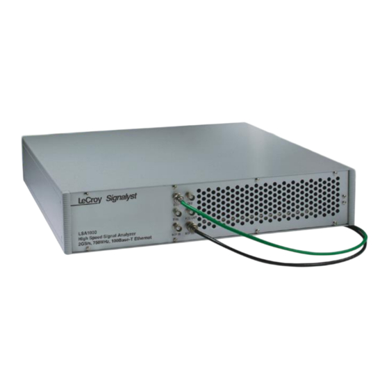
- Page 1 LeCroy LSA1000-09 Signalyst In Stock Used and in Excellent Condition Open Web Page https://www.artisantg.com/57800-1 A l l t r a d e m a r k s , b r a n d n a m e s , a n d b r a n d s a p p e a r i n g h e r e i n a r e t h e p r o p e r t y o f t h e i r r e s p e c t i v e o w n e r s .
- Page 2 Operator’s Manual LeCroy Signalyst LSA1000 Revision B — October 1998...
-
Page 3: Corporate Headquarters
Tel: (41) 22 719 21 11, Fax: (41) 22 782 39 15 Internet: www.lecroy.com Copyright © October 1998, LeCroy. All rights reserved. Information in this publication supersedes all earlier versions. Specifications subject to change. LeCroy, ProBus and SMART Trigger are registered trademarks of LeCroy Corporation. MathCad is a registered trademark of MATHSOFT Inc. -
Page 4: Table Of Contents
Contents Foreword Explaining the LSA1000 ................. v LSA1000: Legacy of the Oscilloscope ..........vi Chapter 1 — Read This First! Warranty and Product Support ............1–1 Chapter 2 — About the LSA1000 What the LSA1000 Does and How ..........2–1 Block Diagram.................. - Page 5 Contents Appendix A — Specifications Appendix B — NET_CON Source Code Appendix C — Parameter Measurement Appendix D — Program Examples Appendix E — Suggestion Forms Index...
- Page 6 Contents...
-
Page 7: Explaining The Lsa1000
Foreword Explaining the LSA1000 The r e a r e t w o m anu a ls t h at ex pl ain t he L SA 1 00 0 . Thi s, th e O pe r at o r’ s M an ua l, t ak e s you t hro ugh the in it ia l st ep s an d g et s you st a rt ed u sin g t he ins tr um ent . -
Page 8: Lsa1000: Legacy Of The Oscilloscope
"ti m e/d iv " , " cu rs or s " , and " di sp la y ". Their presence in dedicated LSA1000 manuals is owing to the legacy of LeCroy DSOs (Digital Storage Oscilloscopes) in the development of the LSA1000. Although the current practicability... - Page 9 Foreword...
-
Page 10: Warranty And Product Support
Products not made by LeCroy are covered solely by the warranty of the original equipment manufacturer. Under the LeCroy warranty, LeCroy will repair or, at its option, replace any product returned within the warranty period to a LeCroy authorized service center. -
Page 11: Service And Repair
Outside the warranty period, you will need to provide us with a purchase order number before we can repair your LeCroy product. You will be billed for parts and labor related to the repair work, and for shipping. - Page 12 How to Return a Product Contact the nearest LeCroy Service Center or office to find out where to return the product. All returned products should be identified by model and serial number. You should describe the defect or failure, and provide your name and contact number. In the case of a product returned to the factory, a Return Authorization Number (RAN) should be used.
- Page 13 LSA1000. ➢ See the Remote Control Manual for questions on specific commands, or if unsure as to which command to use. ➢ Check Frequently Asked Questions at the LeCroy web site: www.lecroy.com …Or Contact LeCroy Embedded Signal Analysis: E-mail: esa@lecroy.com...
- Page 14 Read This First! 1–1...
-
Page 15: What The Lsa1000 Does And How
About the LSA1000 What the LSA1000 Does and How The LSA1000 is an ideal instrument for capturing, digitizing and analyzing high-speed electronic signals. Moreover, it has been optimized for system-integration applications with high throughput, ease of use and reliability. The host computer can easily control and retrieve data from the LSA1000 via a 10/100Base-T Ethernet interface. -
Page 16: Block Diagram
Block Diagram Signalyst ➢ LSA1000 What Can it Do? The LSA1000 delivers the same powerful performance as a high-end LeCroy DSO (Digital Storage Oscilloscope) in a design optimized for system integration, with: ➢ Capture of one-off (single-shot) events, stored in memory ➢... -
Page 17: Input Amplifier
System Acquisition Input Memory Amplifier Memory Signal Up to 64 Mb Processor Record Length Bandwidth Sample Rate Computer Basic Elements These are the basic elements that make up the LSA1000: ➢ Amplifier — amplifies and conditions the input signal so that it can be measured most effectively ➢... - Page 18 About the LSA1000 ➢ Processor — a PowerPC 603e microprocessor controls the entire system and performs computations and special monitoring. ➢ Interfaces — Ethernet port transfers processed data to the host computer and receives remote control instructions. Finding the “Right Fit” For optimum results there must first be a good “fit”...
-
Page 19: Capture
Capture In addition to the primary specifications and three parameters described above, capture techniques, the triggering system, channels and ADC specification all impact on LSA1000 performance. Acquisition Technique Single-shot acquisition is the LSA1000’s basic acquisition technique, which makes the instrument very suitable for the study of signal phenomena that have a low-repetition rate or are not repeated —... - Page 20 About the LSA1000 Channels The LSA1000 offers two channels for signal input. There are four additional BNC connectors for an external trigger channel, external reference clock in, external reference clock out and acquisition status output. The LSA1000 can be “stacked” to provide more channels and parallel processing with multiple units.
- Page 21 The amplitude and range of trigger signals and levels are limited as follows: ➢ ECL or TTL threshold crossing with EXT as trigger source. Upper Region Trigger Level Lower Region Time Triggers Edge Window Trigger: trigger when the signal leaves the window region. ➢...
- Page 22 About the LSA1000 Trigger Modes STOP This command halts the acquisition in any of the three re-arming modes: Auto, Normal or Single. Issuing the STOP command prevents the LSA1000 acquiring a new signal. Issue STOP while a single-shot acquisition is under way and the last acquired signal will be kept.
-
Page 23: Measure
Waveform mathematics can yield final answers instead of raw data. For example, inputs from voltage and current transformers can be multiplied together to calculate power. An important LeCroy LSA1000 feature is the ability to ‘daisy-chain’ math functions: a power trace can be integrated to calculate energy, for instance. -
Page 24: Analyze
LSA1000’s internal digitizer processor or by an external computer. Most current digitizers have a wide analysis spectrum built-in. Depending on its options, LeCroy LSA1000s offer a selection of the following analytical features. Time Domain The optional time domain waveform analysis package —... - Page 25 A 10/100Base-T Ethernet port is provided for control and transfer of data to and from the LeCroy LSA1000. Remote Control is via a subset of the standard LeCroy DSO remote commands with enhancements specific to the LSA1000. TCP/IP protocol is used for Ethernet communication. See the Remote Control Manual.
-
Page 26: The Lsa1000 - Front And Back
About the LSA1000 The LSA1000 — Front and Back Front Panel ➢ CH 1 and CH 2: signal input channels ➢ LED Power Indicator: indicates power on/off status ➢ Secondary Power Switch: power on/off switching ➢ External Reference Clock In: allows the instrument to be synchronized to an external 10 MHz reference. -
Page 27: Rear Panel
Rear Panel ➢ Ethernet Interface Port: to transfer data and to receive remote commands from the host computer ➢ Main Power Switch: power on/off switching ➢ USB port: Currently disabled. Provision future enhancement. Note: All six BNC connections may be located on the LSA1000 rear, rather than front, panel, depending on the instrument’s mechanical configuration. - Page 29 About the LSA1000 2–1...
-
Page 30: Installation For Safe And Efficient Operation
Installation and Safety Installation for Safe and Efficient Operation For safe operation of the LSA1000 to its specifications, ensure that the operating environment is maintained within the following parameters: Operating Environment ➢ Indoor use only ➢ Temperature ......5 to 40 C (41 to 104 F) ➢... - Page 31 The LSA1000 has not been designed to make direct measurements on the human body. Users who connect a LeCroy instrument directly to a person do so at their own risk. Power Requirements The LSA1000 operates from a 115 V (90–132 V) or 220 V (180–250 V) AC (~) power source at 45–66 Hz, and draws 200 W max power.
- Page 32 Cleaning and Maintenance Maintenance and repairs should be carried out exclusively by a LeCroy technician (see Chapter 1). Cleaning should be limited to the exterior of the instrument only, using a damp, soft cloth. Do not use chemicals or abrasive elements. Under no circumstances should moisture be allowed to penetrate the instrument.
- Page 33 Installation and Safety auxiliary On/Off switch, located on the front panel. After the instrument is switched on, auto-calibration is performed. CAUTION Do not exceed the maximum specified signal input voltage levels (see Appendix A for details). 3–4...
- Page 34 Installation and Safety 3–1...
-
Page 35: Connecting The Lsa1000 To Its Host
Connecting to PC or Network Connecting the LSA1000 to its Host This chapter describes connecting the LSA1000 to the host PC or network over the standard 10/100Base-T Ethernet. Windows NT and Windows 95 operating systems are supported. For more about the LSA1000 and the Ethernet, see Chapter 3 of the accompanying Remote Control Manual. -
Page 36: Configuring The Pc
Connecting to PC or Network Configuring the PC Before establishing a direct connection between the LSA1000 and the host computer, the PC must first be properly configured. Note: The following A specific TCP/IP address must be assigned — known as "static examples assume that the addressing". - Page 37 3. Double-click on the line. A dialog box similar to the one below appears. Select 4. If this has already been selected, then the computer’s static address is set and nothing more needs to be done. Cancel out of the TCP/IP and network dialog boxes and close the control panel.
-
Page 38: Verifying Connection
Connecting to PC or Network 5. However, if the address has not already been selected, fill in the IP address and subnet mask as shown above. The subnet mask for 172.25.x.x is 255.255.0.0. If the computer will not be plugged into a network, the above address (or almost any address within the chosen subnet) will do. - Page 39 The ping command has sent a message to the instrument and waited for a response. But if a timeout occurs, as is shown in box on the next page, the IP address used for the destination (the LSA1000) is incorrect or not within the subnet mask of the PC’s IP address.
-
Page 40: Network Connection
Connecting to PC or Network Network Connection Check with your network administrator before connecting the LSA1000 to a network. Incorrect addresses on a network can cause both the network and the LSA1000 to behave strangely! However, a network connection ought to be as simple as plugging the LSA1000 into the network. -
Page 41: Changing Ip Address
Note: The default Gateway is assigned as "172.25.0.1" unless your network has this Gateway available, you must ensure the computer and the LSA1000 are on the same subnet. Changing IP Address Once communication between the LSA1000 and host PC has been verified, the IP address can be easily reset to any address using the Scope Explorer remote control software tool provided in the Getting Started CD-ROM. - Page 42 Connecting to PC or Network Example of responses for * IDN and CONET? queries. 4–8...
- Page 43 Connecting to PC or Network 4–1...
-
Page 44: Introducing The Lsa1000 Software
And because it is designed specifically for use with LeCroy instruments, ScopeExplorer allows these tasks to be completed with only a few keystrokes or mouse clicks. See page 5–19. - Page 45 LSA1000 Software Tools NET_CON When complied target system, this program demonstrates the implementation of a BSD socket under Microsoft Developer Studio 5.0. The TCP/IP protocol is accessed using this “socket”, which is platform-independent. For non- Windows systems such as the UNIX-based workstation, the “NET_CON”...
-
Page 46: Installing And Launching Software
Installing and Launching the Software Included with the LSA1000 software tools on the CD-ROM are the source codes for all the programs. Provided as reference materials for software development, depending on the application they can be directly copied into your program. Note: 1. - Page 47 LSA1000 Software Tools Remote LSA Panel. The Timebase + Trigger control panel is displayed here (see following sections). Remote LSA Menu standard menus described here: ➢ File Connection creates a new connection. ➢ File Exit returns operating system. 5–4...
- Page 48 ➢ Option Re-sync Panel loads all the current values from the instrument. ➢ Option Change Color opens a window that allows the user to change the color of waveform traces, the grid, and the screen. Chosen colors replace the default colors. ➢...
-
Page 49: Operating The Lsa1000 Using
LSA1000 Software Tools Remote LSA Operating the LSA1000 Using Remote LSA offers control panels for operating all the major LSA1000 functions, simulating front-panel oscilloscope controls. Five control panels provide this scope-like graphical user interface: “Timebase”, “Channel”, “Zoom Math”, “Utility”, and “Command Panel”. The desired panel is selected by clicking on its tab. -
Page 50: Channel Offset
is a spin button used to adjust pre- or post-trigger delay. is a fly-out menu giving the valid sweep rates. Channel Offset This control panel is accessed by clicking on are toggle buttons that change the display status of the corresponding channel. toggle buttons provide a mechanism for changing the “active”... - Page 51 LSA1000 Software Tools Zoom + Math This control panel is accessed by clicking on enables or disables the display status of the corresponding memory. toggle buttons to choose the active memory trace. spin buttons allow the active memory trace to be expanded horizontally.
-
Page 52: Display + Utility
Display + Utility This control panel is accessed by clicking on turns the 8 x 10 division display grid on or off. enables or disables a pair of cursors on each active trace. The time and amplitude difference between the cursors on the active trace is displayed at the bottom of the screen. - Page 53 LSA1000 Software Tools Command/Reply This control panel is accessed by clicking on is the window for remote command input to the LSA1000. Refer to the Remote Control Manual. executes all the commands listed in the window. displays the text messages returned by the LSA1000.
-
Page 54: Performance Verification With
Remote LSA Performance Verification with Remote LSA is the simplest way to run the LSA1000’s basic — without the need for remote control operations commands. Thus we recommend that Remote LSA be used for the initial performance verification of the LSA1000. 1. - Page 55 LSA1000 Software Tools Remote LSA display of LSA1000’s External Reference Out Waveform. 5–12...
-
Page 56: Using Activedso
ActiveDSO Using ActiveDSO is highly suitable for fast program development in the Microsoft environment. This LSA1000 program is a control of ActiveX, the software technology developed by Microsoft as a subset of its COM model. ActiveDSO facilitates the programming with the LSA1000 by providing a ready interface between the instrument and the host computer. - Page 57 LSA1000 Software Tools Example: PowerPoint This example shows the control being embedded into a Microsoft PowerPoint slide. The waveform captured by the LSA1000 can be simply imported into PowerPoint with just a few mouse clicks: Note: this example 1. Ensure that the ActiveDSO files from the CD-ROM are assumes that installed on the PC.
- Page 58 5. From the pop-up window, select LeCroy ActiveDSO object as shown here: 6. Right-click on the object and select “Make Connection”. 5–15...
- Page 59 LSA1000 Software Tools 7. Select “Network” “TCP/IP connection” as shown here (for “scope” read LSA1000): 8. Enter the LSA1000’s IP address and click “OK”. 5–16...
- Page 60 9. Right-click on the object again and select the “Refresh Image” menu item. A captured waveform will be displayed similar the one shown here: LSA1000’s captured waveform imported into PowerPoint. Once the ActiveDSO™ object has been properly set within the application, macro script can be created utilizing an object method such as SendString() to send DISP ON, C1:TRA ON, TRMD...
- Page 61 The following VBA subroutine demonstrates how easy it is to connect to an LSA1000 and send remote commands to it. _______________________________________________ ________ Sub LeCroyDSOTest() Dim o As Object CreateObject("LeCroy.ActiveDSO.1") Call o.AboutBox Present control's About box Call o.MakeConnection("IP:172.25.1.2") Connect to the unit Call o.WriteString("DISP ON", 1)
-
Page 62: Using Scopeexplorer
ScopeExplorer Using 1. Start ScopeExplorer. 2. Click on “Scope > Scope Finder”. 3. In the “Scope Selector” window, click “OK”, as below. 4. When the ADD DEVICE window opens, select "Network". (If you don’t see “Network” button, press “ALT + N” simultaneously.) 5. - Page 63 LSA1000 Software Tools 5–20...
- Page 64 ➢ IP address change: ScopeExplorer can be used to change the IP address of the LSA1000. See Chapter 4 for details. ScopeExplorer is supported for all LeCroy instruments and additional information can found on the LeCroy web site: www.lecroy.com 5–21...
-
Page 65: About Net_Con
Windows environment can be found on the CD and in Appendix B this manual. When the program is run, the LSA1000 will return the ID string “LECROY, LSA1000, LSA1000000000, 01.0.0”. For Unix based workstation, the NET_CON sample program provides the baseline implementation of a stable TCP/IP communication between the LSA1000 and the computer system. - Page 66 LSA1000 Software Tools 5–1...
-
Page 67: Appendix A: Specifications
Appendix A: Specifications Signal Capture Acquisition System Bandwidth (-3 dB): @50 : DC to 1 GHz Number of Channels: 2 Number of Digitizers: 2 S amp li ng Ra t e: 2 c h. in us e : 1 M S /s to 1 G S/s 1 c h. -
Page 68: Timebase System
Appendix A Timebase System Capture Time Window: Acquisition Memory: 100kpts/ch on 2 active channels; 200kpts/ch on 1 active channel. Larger memory options available Memory @ 1GS/s @ 1MS/s 100K 0.1 ms 100 ms 500K 0.5 ms 500 ms 1 ms 2 ms 4 ms ... -
Page 69: Triggering System
Specifications Triggering System Modes: Normal, Auto, Single, Stop Sources: CH1, CH2, Ext; Slope: CH1, CH2: Positive, Negative, Window Ext: Positive, Negative Coupling: DC Pre-trigger Recording: 0–100 % of record size adjustable in 1 % increments Post-trigger Delay: 0–1,000 times record size adjustable in 1% increments Internal Trigger Range: ±... -
Page 70: Signal Analysis
Appendix A Signal Analysis Waveform Processing Processing functions: Add, Subtract, Multiply, Divide, Negate, Identity, Summation Averaging, and Sine x/x; four functions performable at one time Average: Summed averaging of up to 1000 waveforms in the basic instrument; up to 10 averages possible with optional WP01 Advanced Waveform Math Package Extrema: Roof, Floor or... - Page 71 Specifications Interfacing Remote Control: By Ethernet for all controls, internal functions Ethernet Port: 10/100Base-T Ethernet Ethernet Protocol: TCP/IP Versatile Instrument Control Protocol (VICP): Protocol that allows Ethernet medium to emulate much of the behavior of GPIB; Remote command set conforms to the IEEE 488.2 standard...
- Page 73 Appendix A: Specifications A–1...
-
Page 74: Appendix B: Net_Con Source Code
Appendix B: NET_CON Source Code NET_CON.CPP LSA1000 Sample Network Connection Copyright (c) 1998 LeCroy Corporation Written By: Ricardo Palacio April, 1998 * $Header:$ * $Log:$ #include <windows.h> #include <winsock.h> #include <stdio.h> #include <time.h> #include "net_con.h" static int hSocket; static int sTimeout = 3;... - Page 75 Appendix B unsigned long argp; if (sConnectedFlag==TRUE) return -1; strcpy(sCurrentAddress, ip_address); tval.tv_sec = sTimeout; tval.tv_usec = 0; if (!sWinsockInitFlag) wVersionRequested = MAKEWORD(1, 1); if (WSAStartup(wVersionRequested, &wsaData) != 0) MessageBox(0, "Unable to initialize the Windows socket environment.", "ERROR", MB_OK); return -1; sWinsockInitFlag = TRUE;...
- Page 76 NET_CON Source Code argp = 1;//non blocking mode ioctlsocket(hSocket, FIONBIO, &argp); connect(hSocket, (SOCKADDR FAR *) &serverAddr, sockAddrSize); result = select(hSocket, NULL, &wr_set, NULL, &tval); argp = 0;//blocking mode ioctlsocket(hSocket, FIONBIO, &argp); /* connect to server (scope) */ if (result < 1) sprintf(tmpStr, "Unable to make connection to IP:%s", ip_address);...
- Page 77 Appendix B int result, bytes_more, bytes_xferd; char *idxPtr; if (sConnectedFlag != TRUE) return -1; if (len < CMD_BUF_LEN) strcpy(sCommandBuffer, buf); // set the header info header.bEOI_Flag = DATA_FLAG; header.bEOI_Flag |= (eoi_flag)? EOI_FLAG:0; header.reserved[0] = 1; header.reserved[1] = 0; header.reserved[2] = 0; header.iLength = htonl(len);...
- Page 78 NET_CON Source Code int TCP_ClearDevice(void) if (sConnectedFlag != TRUE) return -1; TCP_Disconnect(); TCP_Connect(sCurrentAddress); return 0; int TCP_ReadDevice(char *buf, int len, int *recv_count) TCP_HEADER header; char tmpStr[512]; int result, accum, space_left, bytes_more, buf_count; char *idxPtr; fd_set rd_set = {1, {0}}; TIMEVAL tval; if (sConnectedFlag != TRUE) return -1;...
- Page 79 Appendix B space_left = len; while (1) // block here until data is received of timeout expires result = select(hSocket, &rd_set, NULL, NULL, &tval); if (result < 1) TCP_ClearDevice(); MessageBox(0, sCommandBuffer, "Read timeout", MB_OK); return -1; // get the header info first accum = 0;...
- Page 80 NET_CON Source Code sprintf(tmpStr, "Read buffer needs to be adjusted, must be minimum of %d bytes", TCP_MINIMUM_PACKET_SIZE); MessageBox(0, tmpStr, "ERROR", MB_OK); return -1; if ((result = recv(hSocket, (char *) idxPtr, (bytes_more>2048)?2048:bytes_more, 0)) < 0) TCP_ClearDevice(); MessageBox(0, "Unable to receive data from the server.", "ERROR", MB_OK); return -1;...
- Page 81 Appendix B char replyBuf[512]; int read; if (argc < 2) printf("\nEXAMPLE: net_con 172.28.11.22\n"); return 0; if (TCP_Connect(argv[1])) return 0; if (TCP_WriteDevice("*idn?\n", 6, TRUE)) TCP_Disconnect(); return 0; if (TCP_ReadDevice(replyBuf, 512, &read)) TCP_Disconnect(); return 0; if (TCP_Disconnect()) return 0; printf("Scope's reply: %s\n", replyBuf); return 0;...
- Page 82 NET_CON Source Code #define TCP_MINIMUM_PACKET_SIZE typedef struct unsigned char bEOI_Flag; unsigned char reserved[3]; iLength; } TCP_HEADER; B–9...
- Page 84 Appendix B: NET_CON Source Code B–1...
-
Page 85: Appendix C: Parameter Measurement
Appendix C: Parameter Measurement Parameters and How They Work In this Appendix, a general explanation of how the instrument’s standard parameters are computed (see below) is followed by a table listing, defining and describing those parameters (page C–1). Determining Top and Proper determination of the top and base reference lines is Base Lines fundamental for ensuring correct parameter calculations. -
Page 86: Determining Time Parameters
Appendix C Determining Rise and Once top and base are estimated, calculation of the rise and fall Fall Times times is easily done (Fig.1). The 90 % and 10 % threshold levels are automatically determined by the LSA1000, using the amplitude (ampl) parameter. -
Page 87: Determining Differential Time Measurements
Parameter Measurement last first delay width width width 50 % (Mesial) PERIOD PERIOD freq = 1/ period duty width/period TWO FULL PERIODS: cycles mean, median, rms, sdev TRIGGER computed on interval periods POINT area, points, data computed between cursors RIGHT CURSOR LEFT CURSOR Figure C–2 To avoid these bias effects, the instrument uses cyclic... - Page 88 Appendix C Noisy spikes ignored due to Hysteresis band HYSTERESIS THRESHOLD Band DATA (1) CLK (2) − c2d (1, 2) c2d+(1, 2) LEFT CURSOR RIGHT CURSOR TRIGGER POINT CLOCK EDGE = Positive Transition DATA EDGE = Negative Transition Figure C–3 Moreover, a hysteresis range may be specified to ignore any spurious transition that does not exceed the boundaries of the hysteresis interval.
- Page 89 Parameter Measurement Pa r am e t er — D es cr ipti o n Definition Notes a m p l Amplitude: Measures difference between top - base On signals having two upper and lower levels in two-level major levels (such as triangle signals.
- Page 90 Appendix C Pa r am e t er — D es cr ipti o n Definition Notes c s d e v Cyclic standard deviation: Standard Where: v denotes measured − mean deviation of data values from mean value sample values, and number over integral number of periods.
- Page 91 Parameter Measurement Pa r am e t er — D es cr ipti o n Definition Notes Duration of acquisition: For single sweep Time from first acquisition — for waveforms, dur is 0; for sequence waveforms: time from first to last average, segment’s trigger;...
- Page 92 Appendix C Pa r am e t er — D es cr ipti o n Definition Notes first Indicates value of horizontal axis at left Horizontal axis Indicates location of left cursor. cursor. value at left Cursors are interchangeable: for cursor example, the left cursor may be moved to the right of the right...
- Page 93 Parameter Measurement Pa r am e t er — D es cr ipti o n Definition Notes median The average of base and top values. Average of base and top (See Fig. C–2) minimum Measures the lowest point in a waveform. Lowest value in Gives similar...
- Page 94 Appendix C Pa r am e t er — D es cr ipti o n Definition Notes r20–80% Rise 20 % to 80 %: Duration of pulse Average duration On signals having two waveform's rising transition from 20% to of rising 20–80 % major levels (triangle or saw- 80%, averaged for all rising transitions transition...
- Page 95 Parameter Measurement Pa r am e t er — D es cr ipti o n Definition Notes Root Mean Square of data between the Gives similar result when applied to cursors — about same as sdev for a time domain waveform or histogram zero-mean waveform.
- Page 97 Appendix C: Parameter Measurement C–1...
-
Page 98: Appendix D: Program Examples
Appendix D: Program Examples Using the LSA1000 Software Tools The application program examples contained in this appendix demonstrate the practical use by remote control of the LSA1000 software tools in real-life applications. Refer to the accompanying Remote Control Manual for the commands. Note: Memory allocation and error handling are not shown. - Page 99 LSA1000 can also be used. In fact, the LSA1000 has the same math functions and processing capability as a high-end LeCroy digital oscilloscope. This Example measures pulse widths of the waveforms that were captured by the LSA1000.
- Page 100 Program Examples Program Code IM_MakeConnection(“IP:172.25.1.2”); // Initialize the unit IM_WriteDevice(“CHDR OFF”); IM_WriteDevice(“TDIV 5us”); IM_WriteDevice(“MSIZ 100K”); IM_WriteDevice(“COMB 2”); IM_WriteDevice(“COMS C1”); IM_WriteDevice(“WFSU NP, 75000, FP, 0”); IM_WriteDevice(“CFMT OFF, BYTE, BIN”); IM_WriteDevice(“TRLV 0”); IM_WriteDevice(“TRSL POS”); IM_WriteDevice(“TRSE EDGE, SR, C1”); Loop IM_QueryDevice(“ARM; WAIT; C1:PAVA? WID”, strBuf, sizeof(strBuf));...
- Page 101 Appendix D IM_MakeConnection(“IP:172.25.1.2”); // Initialize the unit IM_WriteDevice(“CHDR OFF”); IM_WriteDevice(“TDIV 5us”); IM_WriteDevice(“MSIZ 100K”); IM_WriteDevice(“COMB 2”); IM_WriteDevice(“COMS C1”); IM_WriteDevice(“WFSU NP, 75000, FP, 0”); IM_WriteDevice(“CFMT OFF, BYTE, BIN”); IM_WriteDevice(“TRLV 0”); IM_WriteDevice(“TRSL POS”); IM_WriteDevice(“TRSE EDGE, SR, C1”); // define the math function IM_WriteDevice(“TA:TRA ON”); IM_WriteDevice(“TA:DEF EQN, ‘PS(FFT(C1))’, MAXPTS, 2500, WINDOW, RECT, DCSUP, OFF”);...
- Page 102 Program Examples Requirement Sample Rate = 1.5GS/s Capture Time = 50us Number of Points = 75,000 LSA1000 Settings Sample Rate = 2GS/s Time per Div. = 5us Memory Size = 100K Program Code IM_MakeConnection(“IP:172.25.1.2”); // Initialize the unit IM_WriteDevice(“CHDR OFF”); IM_WriteDevice(“TDIV 5us”);...
- Page 103 Appendix D IM_QueryDevice(“INR?”, strBuf, sizeof(strBuf)); If (strBuf indicates a flag is set) Break; // loop until math processing completes on trace B Loop IM_QueryDevice(“INR?”, strBuf, sizeof(strBuf)); If (strBuf indicates a flag is set) Break; IM_QueryDevice(“TB:WF? DAT1”, Buffer, BufferSize); IM_Disconnect(); D–6...
- Page 104 Appendix D: Program Examples D–1...
- Page 105 These suggestion forms covering the LSA1000 and its manuals are a means by which you can communicate to us what you like, and what you think can be improved. LeCroy welcomes your suggestions on product improvement or ideas for new products. Name: Title:...
- Page 106 Appendix E LeCroy welcomes your comments on: Signalyst Operator’s Manual Rev A Remote Control Manual Rev A The LSA1000 , and Name: Title: Company: Address: Phone: Fax: Email: How would you like the manuals to be changed? Did you find any errors in the manuals? If so, please record them below, including the name of the manual and page number(s) concerned.
-
Page 107: Appendix E: Suggestion Forms
Appendix E: Suggestion Forms E–1... - Page 108 Index...
- Page 110 Index Cycles, C-5 in parameter measurements, Acquisition Memory, 2-3, 2-4, A-1 Cyclic Mean, C-5 increasing it by combining Cyclic Median, C-5 channels, 2-1 Cyclic Parameters, C-3 Acquisition Modes, A-1 Cyclic Root Mean Square, C-5 Acquisition Status, 2-12 Cyclic Standard Deviation, C-6 Acquisition Summary, 2-8 ActiveDSO, 5-1, 5-3, 5-13 ActiveX, 2-11, 5-13, 5-18...
- Page 111 Index Find, 5-7 First, C-8 NET_CON, 5-2, 5-21, B-1 Frequency, C-8 Network Frequency Domain, 2-10 connection, 4-6 Frequency Range, A-1 Norm, 5-6 Front Panel, 2-12 NORM, 2-8 Fuses, 3-3 Offset (V), 5-7 Grid, 5-9 Offset Range, A-1 OLE, 5-13 Operating Environment, 3-1, A-5 H Mag, 5-8 Over-, C-9 Histograms, 2-10, A-4, C-1...
- Page 112 Stop, 5-6 System Memory, 2-3 RAM, 2-3 amount needed for LSA1000, 4-1 TCP, 4-2, 4-3, 4-4, 5-21 Rear Panel, 2-12 TCP/IP, 2-11, 5-3, 5-16, 5-21 Remote LSA, 2-11, 5-1, 5-3, 5-5, Temperature, 3-1 5-11 LSA1000 Series, A-5 Reply, 5-10 Time at Level, C-11 Reset, 5-8 Time Domain, 2-10 Return, 1-3...
- Page 113 Index Warnings, 3-2 Warranty, 1-1, A-5 Waveform Math, 2-9 Waveform Processing Averaging, D-5 FFT, D-3 pulse parameters, D-2 Weight, A-5 Width, C-11 Windows, 4-1, 4-4, 5-3, 5-21 WinSock, 5-21 Zoom + Math, 5-8...
- Page 114 Index...
Need help?
Do you have a question about the Signalyst LSA1000-09 and is the answer not in the manual?
Questions and answers