Table of Contents
Advertisement
Advertisement
Table of Contents

Related Manuals for Cardinal 212X Series


Summarization of Contents
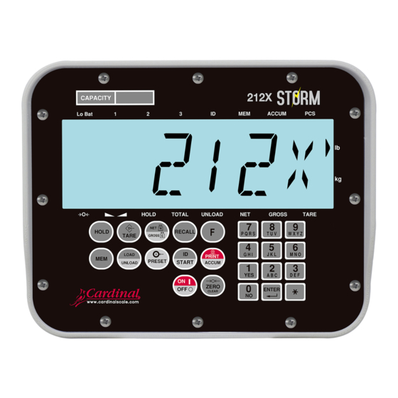
Overview of Cardinal Model 212/212X Indicator
Specifications
Technical details of the indicator's capabilities and physical attributes.
Model Number Description
Explains the different model designations and their variations.
Standard Features
Lists the key functionalities and capabilities built into the indicator.
Options
Details available add-on features and functionalities.
Accessories
Lists optional components and parts for the indicator.
Precautions
Provides important safety and handling guidelines.
Static Electricity Precautions
Safety guidelines to prevent damage from electrostatic discharge.
Key Descriptions
Explains the function of each key on the indicator's keypad.
Annunciators
Describes the various indicator lights and their meanings.
Getting Started with Your Indicator
Installation Guide
Guides on setting up the indicator, including connections and mounting.
Site Preparation Requirements
Recommendations for the physical environment for installation.
Environmental Operating Conditions
Specifies the operating temperature range for the indicator.
Electrical Power Requirements
Details the power requirements and connection methods.
Transient Suppression
Recommendations to protect against electrical transients.
RFI Immunity Guidelines
Guidelines to maximize protection against radio frequency interference.
Mounting Instructions
Instructions and diagrams for physically mounting the indicator.
Installing the Wall Bracket
Step-by-step guide for mounting the wall bracket.
Cable Connections
Explains how to connect various cables to the indicator.
Optically Isolated Inputs
Describes the use and configuration of programmable inputs.
Optically Isolated Outputs
Explains how to use optically isolated outputs for control.
Optional DC Output Relay Board
Information on the optional relay board for output control.
Main PCB Overview
Diagram and overview of the main circuit board.
Main PCB Jumpers
Explains the function and configuration of PCB jumpers.
Indicator Setup
Covers the process of configuring the indicator's parameters.
Setup Data Entry
Instructions on how to input data during setup.
Quick Calibration Procedure
Step-by-step guide for performing a basic calibration.
Full Setup and Configuration
Detailed procedure for comprehensive setup and configuration.
Settings Configuration
Configuration options for various indicator parameters.
Analog to Digital Filtering
Explanation of digital filtering settings for signal processing.
Filter Setting Recommendations
Guidance on choosing appropriate filter settings.
Calibration Procedures
Detailed procedures for calibrating the scale indicator.
Serial Input/Output Configuration
Configuration of serial communication parameters.
Print Tab Settings
Options for configuring print outputs and data formatting.
Fine Span Adjustment
Procedure for adjusting the span calibration.
Display High Resolution Weight
How to view weight readings in high resolution mode.
Key Lock Out Function
Feature to disable keypad functions during operation.
Storing and Restoring Indicator Defaults
How to save and load default settings.
Indicator Setup Review
How to review indicator settings without full reconfiguration.
Accessing Setup Review
Steps to enter and navigate the setup review mode.
Operational Setup Review
How to review operational parameters.
Accessing Operational Setup Review
Steps to access and use the operational setup review.
Operation Guide for Your Indicator
Standard Weighing
Procedure for performing standard weight measurements.
Subtractive Weighing
Procedure for weighing using the subtractive method.
Auto-Hold for Animal Weighing
How to use the auto-hold feature for weighing animals.
Preset Weight Comparator (PWC)
Using the PWC feature to compare weights against presets.
Digital Fill Control (DFC)
Detailed explanation of the Digital Fill Control features.
Specified Target Weight DFC
Using DFC to achieve a specific target weight.
Simple DFC (Simple-Fill)
Configuration and use of the Simple-Fill DFC mode.
Box-Tracker DFC Mode
Using DFC for box filling operations.
Plot-Tracker DFC Mode
Using DFC for plot tracking and material delivery.
Using Memory/ID Storage
How to store and manage IDs and associated data.
Adding an ID to Memory
Step-by-step guide to creating and saving new IDs.
Service and Maintenance Information
Troubleshooting Guide
Guide to diagnose and resolve common issues.
Error and Status Messages
Explains displayed error codes and status messages.
Care and Maintenance
Guidelines for cleaning and maintaining the indicator.
Parts List
Lists and illustrates the components of the indicator.
Rear Sub-Assembly Parts
Diagram and parts list for the rear section.
Front Sub-Assembly Parts
Diagram and parts list for the front section.
Final Assembly Diagram
Diagram showing how the main components assemble.
Statement of Limited Warranty
Warranty Limitations and Requirements
Details the terms, conditions, limitations, and requirements of the warranty.
Need help?
Do you have a question about the 212X Series and is the answer not in the manual?
Questions and answers