Champion Eseries Installation/Operation With Service Replacement Parts

Champion Eseries Installation/Operation With Service Replacement Parts

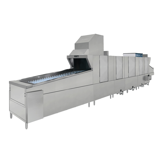
High temperature upright conveyor dishwasher
Table of Contents

Advertisement

Installation/Operation with Service Replacement Parts
Beginning with Serial No. J2089 and above
EUCCW-8 / EUCC-8
EUCCW-6 / EUCC-6
EUCCW-4 / EUCC-4
LISTED
www.championindustries.com
3765 Champion Boulevard,
Winston-Salem, NC 27105
336/661-1556 Fax: 336/661-1660
Toll-free: 800.858.4477
2674 N. Service Road, Jordan Station
Ontario, Canada L0R 1S0
905/562-4195 Fax: 905/562-4618
Toll-free: 800.263.5798
Eseries
High Temperature
Upright Conveyor Dishwasher
Models:
EUCCW
29" wide conveyor with a 4', 6',or 8'
center section
EUCC
24" wide conveyor with a 4', 6',or 8'
center section
Issue Date: 2.28.17
Manual P/N
114254
For machines beginning with S/N J2089 and above
Printed in USA
rev. i

Advertisement

Table of Contents
loading

Summary of Contents for Champion Eseries

  • Page 1 LISTED Manual P/N 114254 rev. i www.championindustries.com For machines beginning with S/N J2089 and above 3765 Champion Boulevard, 2674 N. Service Road, Jordan Station Printed in USA Winston-Salem, NC 27105 Ontario, Canada L0R 1S0 336/661-1556 Fax: 336/661-1660 905/562-4195 Fax: 905/562-4618 Toll-free: 800.858.4477...
  • Page 2 ATTENTION: The dishwasher model no., serial no., volt- age, Hz and phase are needed to identify your machine and to answer questions. Please have this information on-hand if you call for service assistance. For all models: The data plate mounts to one side of the top-mounted control cabinet.
  • Page 3 Two ways to REGISTER YOUR PRODUCT and ACTIVATE YOUR WARRANTY. 4:34 PM • Use your mobile or computer to go to our website at www.championindustries.com and register your product there. • Use the fax form on the next page.
  • Page 4 PRODUCT REGISTRATION BY FAX COMPLETE THIS FORM AND FAX TO: (336) 661-1660 in the USA 1-(800) 204-0109 in Canada PRODUCT REGISTRATION CARD Model Serial # Date of Installation: Company Name: Address: (Street) Province Postal Code Telephone #: ( Contact: Installation Company: Address: Telephone #: Contact:...
  • Page 5: Revision History

    Revision History Revision History Revision Revised Serial Number Revision Date Pages Effectivity Description 3.16.07 J2089 Issue of First Edition 3.22.07 J2089 Revised Parts Format 7.27.07 J2089 Added 575VAC Parts 11.18.08 J08102541 Added Digital Display 10.5.09 ------- Changed P/N's for Clutch 12.6.09 63-71 J09062644...
  • Page 6 Dear Owner: Thank-you for choosing our dishwasher. We appreciate your business. This manual covers two models: EUCCW Electric high temperature flight-type conveyor dishwasher with built-in EUCC electric booster in 40° F/22° C rise or an optional 70° F/39° C rise booster. EUCCW Steam high temperature flight-type conveyor dishwasher with built-in EUCC steam booster in 40° F/22° C rise or an optional 70° F/39° C rise booster. The installation, and initial start-up of your dishwasher must be performed by qualified electricians, plumbers, and authorized service technicians trained in commercial dishwashers.
  • Page 7: Table Of Contents

    Table of Contents Table of Contents E series Upright Conveyor Dishwashers Revision History ___________________________________________________________________ i Limited Warranty _________________________________________________________________ iv Operating Instructions ___________________________________________ 1 Construction How to Operate your Dishwasher Cleaning and Maintenance Troubleshooting Installation _____________________________________________________ 21 The plumbing and electrical connection diagram, (P&E). Unpack and Place Order of Assembly Section Assembly...
  • Page 8: Limited Warranty

    If a defect in workmanship or material is found to exist within the warranty period, Champion, at its election, will either repair or replace the defective machine or accept return of the machine for full credit; provided;...
  • Page 9: Operating Instructions

    Keep these instructions available for quick reference. Contact your supervisor immediately if you have questions about the dishwasher. Contact your local authorized Champion service agency for technical support. Our National Service Department provides 24 hour support 365 days a year with a Toll-free number in the United States.
  • Page 10: Construction

    Dishwasher Construction Operating Instructions Dishwasher Construction 1. The Upright Conveyor dishwasher, (also called the flight-type conveyor), is assembled as a single unit from sections or modules. 2. This basic design is then customized to the customer's specifications. 3. The information presented blow explains the basic construction of the upright conveyor dishwasher.
  • Page 11 Operation Operating Instructions All Models The diagrams below are an example, your machine may be different. WASH/RINSE "C" UNLOAD END "B" LOAD END "A" RINSE "C1" WASH "C1" FINAL POWER POWER PREWASH RINSE RINSE WASH DIRECTION OF OPERATION...
  • Page 12 Operation Operating Instructions DO NOT flip the dishwasher power switch "ON" until you check the items below. 1. Check that the following utilities are connected: to the dishwasher and ready for use:  Electrical service  Hot water supply  Drain ...
  • Page 13 Operation Operating Instructions Close all drains. Make sure floats, overflows, drain screens, and pump screens are clean and in place. Always slide the pump screens up and lift out. Check the bottom to make absolutely sure they are clean. Replace in reverse order...
  • Page 14 Operation Operating Instructions Place the curtains in the dishwasher making sure the short flaps face the load end of the machine. To install the curtains: Locate the curtain hooks in each section. Place the curtain rod in the rear hook, then lift the opposite end of the curtain rod and place it in the front hook.
  • Page 15 Operation Operating Instructions Check the upper and lower wash arm manifold o-rings to make sure they are in place and in good condition. Install the upper wash arm assemblies. Install the lower wash arm assemblies. Make sure all wash arm assemblies are locked in place.
  • Page 16 Operation LOCKING SLOT Operating Instructions TO REMOVE UPPER SPRAY ARM: TO INSTALL UPPER SPRAY ARM: LOCK RELEASES LOCKING LOCKING SLOT SLOT PREVENTS SPRAY ARM FROM DROPPING LOCKING LOCKING SLOT SLOT TAB PREVENTS SPRAY ARM FROM DROPPING TO REMOVE UPPER SPRAY ARM: LOCK RELEASES LOCKING SLOT...
  • Page 17 Operation Operating Instructions There are 2 removable auiliary rinse spray pipes in the auxiliary rinse section. Make sure the upper and lower auxiliary rinse spray pipe gaskets are in place. Position the spray pipe so the rinse nozzle points toward 10 o'clock. Push the rinse pipe forward.
  • Page 18 Operation Operating Instructions Install the scrap screens. 18. Install the scrap baskets if applicable. Make sure the screens are fully seated to the rear of the dishwasher and interlocked into the scrap basket.
  • Page 19 Operation Operating Instructions Close all doors. Lift the door up slightly, then push the door catch back toward the inside of the dishwasher. Slowly lower the door. The door catch remains disengage There are 2 half-size Econo-rinse doors. The operator lifts the upper door which hooks in place. Next, he lifts the lower door which hooks in front of the upper door.
  • Page 20 Operation Operating Instructions Flip the dishwasher power switch up. The dishwasher automatically fills with water. The tank heat comes on as soon as the tanks are full. Wait for 15-20 minutes to allow the wash and rinse tanks to reach operating temperature. R-L shown The prewash tank is not heated so its temperature may be lower than the wash tank.
  • Page 21 Operation Operating Instructions Push the GREEN START BUTTON to start the NOTE: Pushing the green start conveyor belt. button: 1. Starts the conveyor belt. Push the RED STOP BUTTON to stop the conveyor belt. The wash pumps stop. Tank heaters continue to operate. Push the GREEN START BUTTON to re-start the conveyor belt.
  • Page 22 Operation Operating Instructions Your dishwasher is equipped with start-stop stations. The load station is standard equipment; the unload station is an option. These stations work exactly as the control cabinet start and stop buttons. Start-stop stations make it possible for the person loading the wares on the conveyor belt to start and stop the dishwasher as needed.
  • Page 23 Operation Operating Instructions An important safety feature designed to stop the con- veyor belt during operation is the shut-off shelf. This device is located at the very end of the unload section. The shut-off shelf moves backward when wares contact it as the belt moves forward.
  • Page 24 Operation Operating Instructions Daily Maintenance Keep your dishwasher and the surrounding area clean. After each meal period or every 2 hours of operation, whichever occurs first and at the end of the day. Turn POWER OFF Drain the dishwasher Remove and clean the curtains Flush the inside of the machine from top to bottom and all hidden places Remove and clean scrap screens and baskets flushing with fresh water Clean drain screens and pump screens...
  • Page 25: Troubleshooting

    Operation Troubleshooting...
  • Page 26: Troubleshooting

    Troubleshooting Troubleshooting On occasion your machine may not operate as expected. Use the checklist below before you decide that a mechanical or electrical failure has occurred. Checklist Are the main disconnect switches, breakers, or motor overloads turned ON? Are the main water and steam supplies turned ON? Are the drain valves closed? Are the spray pipes and rinse nozzles clean? Are the spray pipes in the proper locations?
  • Page 27: Troubleshooting

    Troubleshooting Troubleshooting CONDITION CAUSE SOLUTION A single pump will not run Motor overload tripped ....... Reset overload in control cabinet Defective motor Contact your service agency Low or no water Main water supply is turned off ..Turn on house water supply Drain valves are open......
  • Page 28: Troubleshooting

    Troubleshooting Troubleshooting CONDITION CAUSE SOLUTION Low final rinse temperature Low incoming water temperature ..Raise incoming water temperature 140°F for 40°F rise booster 110°F for 70°FS rise booster 180°F without booster Defective thermometer ......Check or replace Defective thermostat ......Recalibrate or replace High limit thermostat tripped ....
  • Page 29 Installation Installation Instructions Plumbing and Electrical Diagram, (P & E) 1. The dishwasher P&E is a documented drawing that contains the critical data for the proper construction and utility connections for the dishwasher. 2. The P&E was reviewed and approved by all authorized persons prior to shipment. 3.
  • Page 30 Blank Page This Page Intentionally Left Blank...
  • Page 31 Installation Installation Instructions 1. The illustrations below are an example machine, your machine may be different. Plan View (machine viewed from above) WASH/RINSE "C" UNLOAD END "B" LOAD END "A" RINSE "C1" WASH "C1" FINAL POWER POWER PREWASH RINSE RINSE WASH DIRECTION OF OPERATION...
  • Page 32: Unpack And Place

    Unpack and Place Installation Instructions Unpack and Place Unpack and place Upright conveyor dishwashers ship in sections. Each section comes wrapped in a protective covering and secured toa wooden pallet. Labels note the totalnumber of sections shipped, such as 1 of 4. Accessories Check the shipment for damage immediately upon receipt.
  • Page 33: Unpack And Place

    Unpack and Place Installation Instructions Unpack and Place Inspect the route that sections must travel if the shipment was not delivered to the dishwashing room. Measure allpassageways and doors before moving the dishwasher. IMPORTANT Check the utilities early Incorrect voltage, hot water supply, or steam piping may delay the completion of the installation Piping on the rear wall of the...
  • Page 34: Order Of Assembly

    Order of Assembly Installation Instructions Order of Assembly Next, compare the site utilities with the utility connections on the dishwasher. The utility locations and ratings of the must match the dishwasher when it is re-assembled in its permanent location. Contact a supervisor immediately if a utility location does not match the dishwasher.
  • Page 35: Order Of Assembly

    Order of Assembly Installation Instructions Order of Assembly 12. The illustration above shows the correct placement of the sections. 13. The recommended spacing between sections is 2 feet. Of course, the size of your dishroom dictates the actual section spacing. 14.
  • Page 36: Section Assembly

    Section Assembly Installation Instructions Section Assembly 19. Remove the shipping braces from the sections. 20. Identify the location of piping between the sections. 21. Check the height of each section and determine which section is the highest due to floor variations. 22. Set the "C" section and adjust to its minimum height.
  • Page 37: Section Assembly

    Section Assembly Installation Instructions 29. Make sure the sections are Section Assembly adjusted to the same height. 30. Check the alignment of the conveyor tracks inside the machine and adjust tracks if necessary. Tracks should align if the sections are level. 31.
  • Page 38: Section Assembly

    Section Assembly Installation Instructions Conveyor Belt Installation Beginning with S/N J11062899 and above 1. Remove the key from the conveyor drive sprocket. 2. Start at the unload end of the machine and pull the conveyor belt around the end sprockets until approximately 1.5 feet/76.2 cm of belt rests on the upper track of the dishwasher.
  • Page 39: Section Assembly

    Section Assembly Conveyor Belt Installation The take-up assemblies are located on either side of the load end conveyor shaft as shown in (A). Belt Access Hole Adjust the conveyor belt tension at the load end. Loosen the adjusting bolt locknuts then turn the adjusting bolts CW to tighten the belt.
  • Page 40 Section Assemby Installation Instructions Conveyor Drive Beginning with S/N J11062899 and above There are two conveyor drive designs. The first is the standard drive comprised of a gear box, drive belt motor and chain connected to the conveyor drive shaft. The second design is variable speed solid-state electronic speed control, a variable speed motor and a chain connected to the conveyor drive shaft.
  • Page 41 Section Assemby Reverse Jog Switch Operation The Single Speed Reverse Jog operates under the following conditions: a) When the power is on and the anti-jam switch is open due to a conveyor jam. b) When the power is on and the conveyor was stopped via the "STOP". The "START" switch must be pressed to restart the forward motion of the conveyor.
  • Page 42: Section Assembly

    Section Assemby Installation Instructions Section Assembly 21. The Installation Supervisor must inspect the position, level and proper connection of the piping connections. 22. Steam supply and condensate unions must be tight. 23. Drain piping must be checked. 24. Cross-flow hoses must be inspected and clamps tightened. 25.
  • Page 43: Section Assembly

    Section Assemby Installation Instructions Section Assembly 26. Check and tighten the fill piping compression fittings. 27. Make sure solenoid coils are positioned correctly on the valve assemblies. 28. Vent stacks must be placed on the hood with vent handles facing the front of the dishwasher. 29. Panels must be rechecked for missing parts, and the location numbers checked with the numbers located on the dishwasher.
  • Page 44: Installation

    Section Assemby Installation Instructions Optional Blower Dryer Assembly The blower dryer comes in electric or steam. REFER TO THE BLOWER- It ships on a separate pallet. DRYER SERVICE MANUAL The vent cowl and mounting hardware are included in the P/N 114316 accessories box and hardware kit.
  • Page 45: Section Assembly

    Section Assemby Installation Instructions Section Assembly Connect the dishwasher internal electric wiring Wires, flex-tite, and some components were disconnected and pulled back to each section, then junction boxes were closed. Open all junction boxes, identify the flex-tite conduit connections, (A) roll-out wire bundles, (B), and match wire numbers attached on wires, (C). Connect the flex-tite conduit to their associated junction boxes.
  • Page 46: Section Assembly

    Section Assemby Installation Instructions Section Assembly - Seal Joint Sections Section joints must be sealed with foodgrade silicon sealant. Mask the joint edges with a quick-release masking tape. Apply a 1/8" bead of Foodgrade silicon sealant. Apply moderate pressure on the gun to ensure the sealant fi lls the joint.
  • Page 47: Section Assembly

    Section Assemby Installation Instructions Section Assembly - Seal Joint Sections Study the photos on the right. The top photo shows a correctly sealed joint. The stainless steel must be wiped with Isopropyl alcohol to remove dust, oil film, and other contaminants. 10. Note that the joint is filled presenting an even transition between sections.
  • Page 48: Electrical Connection

    Supply Connections Installation Instructions Supply Connections - Main Incoming Power The Main incoming power to the dishwasher is made at the top of machine in the control cabinet. The electrician must connect the power supply in accordance with the data stamped on the Machine Electrical Connection Plate.
  • Page 49: Drain Connection

    Supply Connections Installation Instructions Supply Connections - Water and Steam IMPORTANT Main utility supply connections must be performed by licenced tradesmen who abide by local building, health and sanitation codes or national codes in the absence of local codes. THE MAIN INCOMING HOT WATER AND STEAM SUPPLY CONNECTIONS ARE MADE IN THE LOWER PART OF "D"...
  • Page 50 Supply Connections Installation Instructions Supply Connections - Chemical Dispensers Chemical dispensing systems are supplied by others. A connection point for detergent, and rinse-aid signals is provided in the in the top-mounted control cabinet. SIGNAL ONLY VENT FAN 120V COMMON RINSE AID 120V COMMON DETERGENT...
  • Page 51: Initial Start-Up

    Supply Connections Installation Instructions Initial Start-up Perform the following checks and adjustments before placing the machine into service. • Check the interior of the machine and remove any foreign material. • Check the exterior of the machine — make sure that the conveyor belt is free of tape and foreign material.
  • Page 52: Electrical Connection

    Initial Start-up Installation Instructions Initial Start-up Check the direction of rotation of the conveyor belt by observing the direction arrow decal on the large conveyor drive sprocket. The sprocket is located on the side of the unload section. If rotation direction is incorrect, reverse wires L1 and L2 on the disconnect switch side of the main electrical connection terminal block located inside the control cabinet.
  • Page 53 Initial Start -up Check the final rinse temperature as the object enters the final rinse area. The Final rinse temperature must be 180-195°F. Adjust the temperature of the incoming water supply if necessary. Adjust the booster thermostat setting if necessary. Check the Final rinse water pressure as the object enters the final rinse area. The final rinse pressure must be 20-22 PSI. Adjust the Pressure Reducing Valve setting if necessary. Check that the pumps and final rinse shut-off before the object reaches the conveyor shut-off shelf. Check that the conveyor belt stops when the object pushes the conveyor shut-off shelf.
  • Page 54 Blank Page This Page Intentionally Left Blank...
  • Page 55: Service Replacement Parts

    Service Replacement Parts Illustration Page Pump/Motor Assembly................................3HP, C3/C4 Pump Installation ..............................1HP, B-30 Prewash Right-Left Pump Installation ........................1HP, B-30 Prewash Left-Right Pump Installation ........................3HP, B-30 Prewash Left-Right Pump Installation ........................3HP, B-30 Prewash Right-Left Pump Installation ........................Auxiliary Rinse Right-Left Pump Installation..........................
  • Page 56: Pump/Motor Assembly

    Pump/Motor Assembly...
  • Page 57 Pump/Motor Assembly 100735 HEX HEAD,1/4-20 X 5/8 SST 100736 HEX HEAD,1/4-20 X 3/4 SS T 100754 SCREW,FLAT HEAD,10-32 X 1/2 SST 102500 PLUG,1/4"NPT SQ.HEAD,BRASS 102504 PLUG,1/2"NPT SQ.HEAD,BRASS 106407 WASHER,LOCK,3/8 SPLIT,SST 106482 WASHER,LOCK,1/4 SPLIT,SST 107690 HEX PLAIN JAM NUT,3/8-16 SST 109654 SLINGER, JET PUMP 110247 HEX PLAIN JAM NUT,7/16-14 SST...
  • Page 58: 3Hp, C3/C4 Pump Installation

    3HP, B4/C3/C4 Pump Installation...
  • Page 59 3HP, C3/C4 Pump Installation 100154 HEX PLAIN NUT,5/16-18 SST 100739 HEX HEAD,5/16-18 X 3/4 SST 100740 HEX HEAD,5/16-18 X 1 SS T 102376 WASHER,FLAT,5/16 x 3/4 x.06 SST 104203 CLAMP,HOSE,M52,71/95,SST GEAR TYPE 104640 GASKET,PUMP SUCTION RACK/CC/UC 106013 WASHER,LOCK,5/16 SPLIT,SST 110372 HOSE,PUMP SUCTION,UC 313300 FLANGE WELD,PUMP SUCTION,UC...
  • Page 60: 1Hp, B-30 Prewash Right-Left Pump Installation

    1HP, B-30 Prewash Right-Left Pump Installation...
  • Page 61 1HP, B-30 Prewash Right-Left Pump Installation 100154 HEX PLAIN NUT,5/16-18 SST 100739 HEX HEAD,5/16-18 X 3/4 SST 100740 HEX HEAD,5/16-18 X 1 SST 102376 WASHER,FLAT,5/16x3/4x.06 SST 104203 CLAMP,HOSE,SST GEAR TYPE 104640 GASKET,PUMP SUCTION RACK/CC/UC 106013 WASHER,LOCK,5/16 SPLIT,SST 109926 FITTING,COMPRESSION,5/8OD X 1/2"MNPT,ELL,BRASS 110372 HOSE,PUMP SUCTION,UC 205192...
  • Page 62: 1Hp, B-30 Prewash Left-Right Pump Installation

    1HP, B-30 Prewash Left-Right Pump Installation...
  • Page 63 1HP, B-30 Prewash Left-Right Pump Installation 100154 HEX PLAIN NUT,5/16-18 SST 100739 HEX HEAD,5/16-18 X 3/4 SST 100740 HEX HEAD,5/16-18 X 1 SST 102376 WASHER,FLAT,5/16x3/4x.06 SST 104203 CLAMP,HOSE,M52,71/95,SST GEAR TYPE 104640 GASKET,PUMP SUCTION RACK/CC/UC 106013 WASHER,LOCK,5/16 SPLIT,SST 109926 FITTING,COMPRESSION,5/8OD X 1/2"MNPT,ELL,BRASS 110372 HOSE,PUMP SUCTION,UC 205192...
  • Page 64: 3Hp, B-30 Prewash Left-Right Pump Installation

    3HP, B-30 Prewash Left-Right Pump Installation...
  • Page 65 3HP, B-30 Prewash Left-Right Pump Installation 100154 HEX PLAIN NUT,5/16-18 SST 100739 HEX HEAD,5/16-18 X 3/4 SST 100740 HEX HEAD,5/16-18 X 1 SST 102376 WASHER,FLAT,5/16x3/4x.06 SST 104203 CLAMP,HOSE,M52,71/95,SST GEAR TYPE 104640 GASKET,PUMP SUCTION RACK/CC/UC 106013 WASHER,LOCK,5/16 SPLIT,SST 109926 FITTING,COMPRESSION,5/8OD X 1/2"MNPT,ELL,BRASS 110372 HOSE,PUMP SUCTION,UC 205192...
  • Page 66: 3Hp, B-30 Prewash Right-Left Pump Installation

    3HP, B-30 Prewash Right-Left Pump Installation...
  • Page 67 3HP, B-30 Prewash Right-Left Pump Installation 100154 HEX PLAIN NUT,5/16-18 SST 100739 HEX HEAD,5/16-18 X 3/4 SST 100740 HEX HEAD,5/16-18 X 1 SST 102376 WASHER,FLAT,5/16x3/4x.06 SST 104203 CLAMP,HOSE,M52,71/95,SST GEAR TYPE 104640 GASKET,PUMP SUCTION RACK/CC/UC 106013 WASHER,LOCK,5/16 SPLIT,SST 109926 FITTING,COMPRESSION,5/8OD X 1/2"MNPT,ELL,BRASS 110372 HOSE,PUMP SUCTION,UC 205192...
  • Page 68: Auxiliary Rinse Right-Left Pump Installation

    Auxiliary Rinse Right-Left Pump Installation...
  • Page 69 Auxiliary Rinse Right-Left Pump Installation 100023 STREET ELBOW,3/4"NPT X 90,SST 100051 NIPPLE,3/4"NPT X CLOSE,SST 100154 HEX PLAIN NUT,5/16-18 SST 100739 HEX HEAD,5/16-18 X 3/4 SST 100740 HEX HEAD,5/16-18 X 1 SST 102376 WASHER,FLAT,5/16x3/4x.06 SST 102554 UNION,3/4"NPT, SST 105993 CLAMP,HOSE,M20,19/44,SST GEAR TYPE 106013 WASHER,LOCK,5/16 SPLIT,SST 108345...
  • Page 70: C8 Wash/Rinse Wash System Installation

    C8 Wash/Rinse Wash System Installation...
  • Page 71 C8 Wash/Rinse Wash System Installation 100734 HEX HEAD,1/4-20 X 1/2 SST 100755 SCREW,FLAT HEAD,1/4-20 X 1/2 SST 104414 O-RING,1 X 1 1/4 X 1/8 106014 HEX ACORN PLAIN NUT,1/4-20 SST 106026 WASHER,FLAT,1/4x5/8x.06 SST 106482 WASHER,LOCK,1/4 SPLIT,SST 108875 COTTER PIN,3/32 X 1/2 UNEVEN 110858 HOSE CLAMP,HIGH PRESSURE,0256 111780...
  • Page 72: 1Hp 30" Prewash Right-Left Wash System Installation

    1HP 30" Prewash Right-Left Wash System Installation...
  • Page 73 1HP 30" Prewash Right-Left Wash System Installation 100734 HEX HEAD,1/4-20 X 1/2 SST 100755 SCREW,FLAT HEAD,1/4-20 X 1/2 SST 104414 O-RING,1 X 1 1/4 X 1/8 106014 HEX ACORN PLAIN NUT,1/4-20 SST 106026 WASHER,FLAT,1/4x5/8x.06 SST 106482 WASHER,LOCK,1/4 SPLIT,SST 108875 COTTER PIN,3/32 X 1/2 UNEVEN 110858 HOSE CLAMP,HIGH PRESSURE,0256 111780...
  • Page 74: 1Hp 30" Prewash Left-Right Wash System Installation

    1HP 30" Prewash Left-Right Wash System Installation...
  • Page 75 1HP 30" Prewash Left-Right Wash System Installation 100734 CAP SCREW,HEX HEAD,1/4-20 X 1/2 SST 100755 SCREW,FLAT HEAD,1/4-20 X 1/2 SST 104414 O-RING,1 X 1 1/4 X 1/8 106014 HEX ACORN PLAIN NUT,1/4-20 SST 106026 WASHER,FLAT,1/4x5/8x.06 SST 106482 WASHER,LOCK,1/4 SPLIT,SST 108875 COTTER PIN,3/32 X 1/2 UNEVEN 110858 HOSE CLAMP,HIGH PRESSURE,0256...
  • Page 76: C4 Single Tank Wash System Installation

    C4 Single Tank Wash System Installation...
  • Page 77 C4 Single Tank Wash System Installation 100734 HEX HEAD,1/4-20 X 1/2 SST 100755 SCREW,FLAT HEAD,1/4-20 X 1/2 SST 104414 O-RING,1 X 1 1/4 X 1/8 106014 HEX ACORN PLAIN NUT,1/4-20 SST 106026 WASHER,FLAT,1/4x5/8x.06 SST 106482 WASHER,LOCK,1/4 SPLIT,SST 108875 COTTER PIN,3/32 X 1/2 UNEVEN 110858 HOSE CLAMP,HIGH PRESSURE,0256 111780...
  • Page 78: C6 Wash/Rinse Wash System Installation

    C6 Wash/Rinse Wash System Installation...
  • Page 79 C6 Wash/Rinse Wash System Installation 100734 HEX HEAD,1/4-20 X 1/2 SST 100755 SCREW,FLAT HEAD,1/4-20 X 1/2 SST 104414 O-RING,1 X 1 1/4 X 1/8 106014 HEX ACORN PLAIN NUT,1/4-20 SST 106026 WASHER,FLAT,1/4 x 5/8 x .06 SST 106482 WASHER,LOCK,1/4 SPLIT,SST 108875 COTTER PIN,3/32 X 1/2 UNEVEN 110858...
  • Page 80: C4 Wash Without Scrap Basket Electric Tank Heat Installation

    C4 Wash without Scrap Basket Electric Tank Heat Installation...
  • Page 81 C4 Wash without Scrap Basket Electric Tank Heat Installation 100007 SCREW,TRUSS HEAD,10-32 x 3/8 SST 100109 WELD-STUD,1/4-20 X 1/2 LG.SST 100154 HEX PLAIN NUT,5/16-18 SST 100198 WELD-STUD,10-32 X 1/2 LG.SST 100547 LOCKNUT,1/2" NPT,SST 100740 CAP SCREW,HEX HEAD,5/16-18 X 1 SST 102376 WASHER,FLAT,5/16x3/4x.06 SST 106013...
  • Page 82: C4 Rinse Without Scrap Basket Electric Tank Heat Installation

    C4 Rinse without Scrap Basket Electric Tank Heat Installation...
  • Page 83 C4 Rinse without Scrap Basket Electric Tank Heat Installation 100007 SCREW,TRUSS HEAD,10-32 x 3/8 SST 100109 WELD-STUD,1/4-20 X 1/2 LG.SST 100154 HEX PLAIN NUT,5/16-18 SST 100198 WELD-STUD,10-32 X 1/2 LG.SST 100547 LOCKNUT,1/2" NPT,SST 100740 HEX HEAD,5/16-18 X 1 SST 102376 WASHER,FLAT,5/16x3/4x.06 SST 106013 WASHER,LOCK,5/16 SPLIT,SST...
  • Page 84: C4 Wash With Scrap Basket Electric Tank Heat Installation

    C4 Wash with Scrap Basket Electric Tank Heat Installation...
  • Page 85 C4 Wash with Scrap Basket Electric Tank Heat Installation 100097 SCREW,TRUSS HEAD,10-32 x 1/2 SS T 100100 SCREW,ROUND HEAD,8-32 x 1/4 SS T 100154 HEX PLAIN NUT,5/16-18 SST 100547 LOCKNUT,1/2" NPT,SST 100740 HEX HEAD,5/16-18 X 1 SST 102376 WASHER,FLAT,5/16x3/4x.06 SST 104985 HEX PLAIN NUT,10-32 SST 106013...
  • Page 86: C4 Rinse With Scrap Basket Electric Tank Heat Installation

    C4 Rinse with Scrap Basket Electric Tank Heat Installation...
  • Page 87 C4 Rinse with Scrap Basket Electric Tank Heat Installation 100097 SCREW,TRUSS HEAD,10-32 x 1/2 SST 100100 SCREW,ROUND HEAD,8-32 x 1/4 SST 100154 HEX PLAIN NUT,5/16-18 SST 100547 LOCKNUT,1/2" NPT,SST 100740 HEX HEAD,5/16-18 X 1 SST 102376 WASHER,FLAT,5/16x3/4x.06 SST 104985 HEX PLAIN NUT,10-32 SST 105695 WELD-STUD,10-32 X 3/8 LG.SST 106013...
  • Page 88: Auxiliary Rinse Tank Heat Installation

    Auxiliary Rinse Electric Tank Heat Installation...
  • Page 89 Auxiliary Rinse Electric Tank Heat Installation 100007 SCREW,TRUSS HEAD,10-32 x 3/8 SST 100109 WELD-STUD,1/4-20 X 1/2 LG.SST 100154 HEX PLAIN NUT,5/16-18 SST 100198 WELD-STUD,10-32 X 1/2 LG.SST 100547 LOCKNUT,1/2" NPT,SST 100740 HEX HEAD,5/16-18 X 1 SST 102376 WASHER,FLAT,5/16x3/4x.06 SST 106013 WASHER,LOCK,5/16 SPLIT,SST 106026 WASHER,FLAT,1/4x5/8x.06 SST...
  • Page 90: Electric Booster Element Configurations

    Electric Booster Element Configuration NOTE: The location of a booster heater element is critical for the proper repair of the booster. VERIFY THE LOCATION OF ITEM NO. 3 EUCCW-6 / EUCC-6 EUCCW-4 / EUCC-4 40°F / 22° Rise BOOSTER ASSY,ELEC,R-L,15kW@208V 100003 HEX PLAIN NUT, 1/4-20 SST 106482...
  • Page 91 Electric Booster Element Configuration NOTE: The location of a booster heater element is critical for the proper repair of the booster. VERIFY THE LOCATION OF ITEM NO. 3 EUCCW-6 / EUCC-8 40°F / 22° Rise BOOSTER ASSY,ELEC,R-L,18kW@208V 100003 HEX PLAIN NUT, 1/4-20 SST 106482 WASHER, LOCK, 1/4 SPLIT SST 107909...
  • Page 92 Electric Booster Element Configuration NOTE: The location of a booster heater element is critical for the proper repair of the booster. VERIFY THE LOCATION OF ITEM NO. 3 & 4 EUCCW-6 / EUCC-6 EUCCW-4 / EUCC-4 70°F / 39° Rise BOOSTER ASSY,ELEC,R-L,25kW@208V 100003 HEX PLAIN NUT, 1/4-20 SST...
  • Page 93 Electric Booster Element Configuration NOTE: The location of a booster heater element is critical for the proper repair of the booster. VERIFY THE LOCATION OF ITEM NO. 3 & 4 EUCCW-8 / EUCC-8 70°F / 39° Rise BOOSTER ASSY,ELEC,R-L,32kW@208V 100003 HEX PLAIN NUT, 1/4-20 SST 106482 WASHER, LOCK, 1/4 SPLIT SST...
  • Page 94 Electric Booster Element Configuration NOTE: The location of a booster heater element is critical for the proper repair of the booster. VERIFY THE LOCATION OF ITEM NO. 3 & 4 EUCC-4 / EUCC-3 40°F / 22° Rise BOOSTER ASSY,ELEC,R-L,16kW@208V 100003 HEX PLAIN NUT, 1/4-20 SST 106482 WASHER, LOCK, 1/4 SPLIT SST...
  • Page 95: Electric Booster Element Configurations

    Electric Booster Element Configuration NOTE: The location of a booster heater element is critical for the proper repair of the booster. VERIFY THE LOCATION OF ITEM NO. 3 & 4 EUCC-4 / EUCC-3 70°F / 39° Rise BOOSTER ASSY,ELEC,R-L,28kW@208V 100003 HEX PLAIN NUT, 1/4-20 SST 106482 WASHER, LOCK, 1/4 SPLIT SST...
  • Page 96: Electric Booster Installation

    Electric Booster Installation...
  • Page 97 Electric Booster Installation 100003 HEX PLAIN NUT,1/4-20 SST 100097 SCREW,TRUSS HEAD,10-32 x 1/2 SST 100100 SCREW,ROUND HEAD,8-32 x 1/4 SST 100109 WELD-STUD,1/4-20 X 1/2 LG.SST 100113 CAP,3/4" NPT SST 100154 HEX PLAIN NUT,5/16-18 SST 100734 HEX HEAD,1/4-20 X 1/2 SST 100736 HEX HEAD,1/4-20 X 3/4 SST 100739...
  • Page 98: Float Switches

    Float Switches Aux. Power Wash Pre- Rinse Rinse Wash...
  • Page 99 Float Switches 111019 FLOAT SWITCH, DUAL (Auxiliary Rinse, Prewash Tank) 113291 FLOAT SWITCH, DUAL (Wash, Power Rinse Tank) 111151 C-Clip (4 per float switch) 104882 WASHER, FLAT .531" X .062" X .062" 107589 WASHER, LOCK 1/2" SPLIT 104584 NUT, PLAIN 1/2-13 HEX SST...
  • Page 100: Final Rinse Installation Eucc8/Euccw8

    Final Rinse Installation EUCC8 / EUCCW8...
  • Page 101 Final Rinse Installation EUCC8 / EUCCW8 (Before 11/18/09) ---- 101529* PLUG 1/8" BRASS SQUARE HD. (Beginning 11/18/09) ---- 114717* BUSHING, RED. 1/2" X 1/8" SST (Beginning 11/18/09)
  • Page 102: Final Rinse Installation C4/C6 Eucc/Euccw

    Final Rinse Installation C4 / C6 EUCC / EUCCW...
  • Page 103 Final Rinse Installation C4 / C6 EUCC / EUCCW 100003 HEX PLAIN NUT,1/4-20 SST 100109 WELD-STUD,1/4-20 X 1/2 LG.SST 100156 LOCKNUT,3/4" NPT,BRASS 100516 STREET ELBOW,1/2"NPT X 90,SST 100734 HEX HEAD,1/4-20 X 1/2 SST 102461 NIPPLE,1/2"NPT X 2"LG.,SST 106026 WASHER,FLAT,1/4 x 5/8 x .06 SST 106482 WASHER,LOCK,1/4 SPLIT,SST 106734...
  • Page 104: Auxiliary Rinse Installation Eucc/Euccw

    Auxiliary Rinse Installation EUCC/EUCCW...
  • Page 105 Auxiliary Rinse Installation EUCC/EUCCW 100003 HEX PLAIN NUT,1/4-20 SST 100109 WELD-STUD,1/4-20 X 1/2 LG.SST 100585 LOCKNUT,1" NPT,BRASS 100734 HEX HEAD,1/4-20 X 1/2 SST 106026 WASHER,FLAT,1/4x5/8x.06 SST 106482 WASHER,LOCK,1/4 SPLIT,SST 106530 NOZZLE,VEE-JET,#8020, SPRAY FAN @20 PSI EUCCW 106530 NOZZLE,VEE-JET,#8020, SPRAY FAN @20 PSI EUCC 113716 WASH-ARMS ORING 113795...
  • Page 106 Blank Page This Page Intentionally Left Blank...
  • Page 107 Blank Page This Page Intentionally Left Blank...
  • Page 108: Cold Water Fill Piping Sub-Assembly

    Cold Water Fill Piping Sub-assembly...
  • Page 109 Cold Water Fill Piping Sub-assembly 100209 NIPPLE,1/2"NPT X CLOSE,BRASS 100500 VACUUM BREAKER,1/2" NPT BRONZE 108349 REPAIR KIT 100704 NIPPLE,RTOE,1/2"NPT X 1 3/4"LG.,SST 100709 LOCKNUT,1/2" NPT,BRASS 102435 ELBOW, 1/2"NPT x 90 DEG,BRASS 102436 ELBOW,1/2"NPT X 90, SST 102438 ELBOW,STREET,1/2"NPT X 90, BRASS 102485 NIPPLE,1/2"NPT X 1 1/2"LG.,BRASS 102582...
  • Page 110: Electric Booster Fill Piping (Prior To S/N J10012728)

    Electric Booster Fill Piping (Prior to S/N J10012728) R-L Direction Shown L-R Direction Shown...
  • Page 111 Electric Booster Fill Piping (Prior to S/N J10012728) Item Part Description Qty. NIPPLE,3/4"NPT X CLOSE,BRASS 100184 UNION,3/4"NPT,BRASS 100571 102444 ELBOW,STREET,3/4"NPT X 90, BRASS 102504* PLUG,1/2"NPT SQ.HEAD,BRASS (Before 11/18/09) 102521 TEE, 3/4"NPT, BRASS 102525 TEE,RED,3/4"x1/2"x3/4"NPT, BRASS 107550 VALVE,PRESSURE REGULATING,3/4"NPT BRONZE FITTING, COMP 7/8 OD X 3/4 MPT BRASS 109879 110768 STRAINER,LINE,3/4"NPT BRONZE FEMALE...
  • Page 112: Electric Booster Fill Piping (Beginning With S/N J10012728 And Above)

    Electric Booster Fill Piping (Beginning with S/N J10012728 and above) R-L Direction Shown L-R Direction Shown...
  • Page 113 Electric Booster Fill Piping (Beginning with S/N J10012728 and above) 100184 NIPPLE, 3/4" NPT X CLOSE BRASS 100209 NIPPLE, 1/2" NPT X CLOSE BRASS 102392 BUSHING, REDUCING, 3/4" NPT X 1/2" NPT BRASS 102438 ELBOW, STREET 1/2" X 90° BRASS 102504 PLUG, 1/2"...
  • Page 114: Fill Piping - No Booster (Prior To S/N J10012728)

    Fill Piping - No Booster (Prior to S/N J10012728)
  • Page 115 Fill Piping - No Booster (Prior to S/N J10012728) 100184 NIPPLE, 3/4" NPT X CLOSE BRASS 102392 BUSHING, REDUCING, 3/4" NPT X 1/2" NPT BRASS 102504 PLUG, 1/2" NPT SQ. HEAD BRASS 102521 TEE, 3/4" NPT BRASS 102526 TEE, RED, 3/4" X 3/4" X 1/2" NPT BRASS 107550 VALVE, PRESSURE REGULATING, 3/4"...
  • Page 116: Fill Piping - No Booster (Beginning With S/N J10012728 And Above)

    Fill Piping - No Booster (Beginning with S/N J10012728 and above)
  • Page 117 Fill Piping - No Booster (Beginning with S/N J10012728 and above) 100184 NIPPLE, 3/4" NPT X CLOSE BRASS 100209 NIPPLE, 1/2" NPT X CLOSE BRASS 102504 PLUG, 1/2" NPT SQ. HEAD, BRASS 102525 TEE, RED. 3/4" X 1/2" X 3/4" NPT BRASS 102526 TEE, RED.
  • Page 118: #120-1 Steam Booster Installation Rl

    #120-1 Steam Booster Installation RL...
  • Page 119 #120-1 Steam Booster Installation RL 100140 HEX PLAIN NUT,3/8-16 SST 100153 HEX HEAD,3/8-16 X 1 SST 100154 HEX PLAIN NUT,5/16-18 SST 100739 HEX HEAD,5/16-18 X 3/4 SST 102376 WASHER,FLAT,5/16x3/4x.06 SST 104618 WASHER,FLAT,3/8x7/8x.06 SST 106013 WASHER,LOCK,5/16 SPLIT,SST 106407 WASHER,LOCK,3/8 SPLIT,SST 112334 U-BOLT,#180 BOOSTER 330244 BASE DECK DEVP,STEAM BOOSTER EUCCW...
  • Page 120: #120-1 Steam Booster Assembly Rl 40-70°F

    #120-1 Steam Booster Assembly RL 40-70°F...
  • Page 121 #120-1 Steam Booster Assembly RL 40-70°F 100123 PETCOCK,1/4"NPT FEMALE,BRASS 100134 ELBOW,STREET,1NPT X 90,MI 100184 NIPPLE,3/4"NPT X CLOSE,BRASS 100209 NIPPLE,1/2"NPT X CLOSE,BRASS 100571 UNION,3/4"NPT,BRASS 100979 BUSHING,REDUCING,1 1/2"NPTx1"NPT,BI 102288 ELBOW,1/2"NPT X 90 DEG,M.I. 102398 BUSHING,REDUCING,1 1/4"NPTx1/2"NPT,BRASS 102399 BUSHING,REDUCING,1 1/4"NPTx3/4"NPT,BRASS 102402 BUSHING,REDUCING,1/2"NPTx1/4"NPT,BI 102435 ELBOW, 1/2"NPT x 90 DEG,BRASS 102438 ELBOW,STREET,1/2"NPT X 90, BRASS...
  • Page 122 #120-1 Steam Booster Assembly RL 40-70°F Item Part Description Qty. 105780 UNION,1"NPT, MALLEABLE IRON 105782 NIPPLE,1/2"NPT X CLOSE.,B.I. 105786 NIPPLE,1/2"NPT X 3" LG.,B.I. 105847 NIPPLE,1"NPT X CLOSE,B.I. 105850 NIPPLE,1"NPT X 2" LG.,B.I. 105881 NIPPLE,1 1/2"NPT X CLOSE,B.I. 106051 STRAINER,LINE,2"NPT B.I. 106428 NIPPLE,1 1/2"NPT X 2"...
  • Page 123 Blank Page This Page Intentionally Left Blank...
  • Page 124: #120-1 Steam Booster Installation Lr

    #120-1 Steam Booster Installation LR...
  • Page 125 #120-1 Steam Booster Installation LR 100140 HEX PLAIN NUT,3/8-16 SST HEX HEAD,3/8-16 X 1 SST 100153 100154 HEX PLAIN NUT,5/16-18 SST 100739 HEX HEAD,5/16-18 X 3/4 SST 102376 WASHER,FLAT,5/16x3/4x.06 SST 104618 WASHER,FLAT,3/8x7/8x.06 SST 106013 WASHER,LOCK,5/16 SPLIT,SST 106407 WASHER,LOCK,3/8 SPLIT,SST 112334 U-BOLT,#180 BOOSTER 330244 BASE DECK DEVP,STEAM BOOSTER EUCCW...
  • Page 126: #120-1 Steam Booster Assembly Lr 40-70°F

    #120-1 Steam Booster Assembly LR 40-70°F...
  • Page 127 #120-1 Steam Booster Assembly LR 40-70°F 100123 PETCOCK,1/4"NPT FEMALE,BRASS 100134 ELBOW,STREET,1NPT X 90,MI 100184 NIPPLE,3/4"NPT X CLOSE,BRASS 100209 NIPPLE,1/2"NPT X CLOSE,BRASS 100571 UNION,3/4"NPT,BRASS 100979 BUSHING,REDUCING,1 1/2"NPTx1"NPT,BI 102288 ELBOW,1/2"NPT X 90 DEG,M.I. 102398 BUSHING,REDUCING,1 1/4"NPTx1/2"NPT,BRASS 102399 BUSHING,REDUCING,1 1/4"NPTx3/4"NPT,BRASS 102402 BUSHING,REDUCING,1/2"NPTx1/4"NPT,BI 102435 ELBOW, 1/2"NPT x 90 DEG,BRASS 102438 ELBOW,STREET,1/2"NPT X 90, BRASS...
  • Page 128 #120-1 Steam Booster Assembly LR 40-70°F Item Part Description Qty. 105780 UNION,1"NPT, MALLEABLE IRON 105782 NIPPLE,1/2"NPT X CLOSE.,B.I. 105786 NIPPLE,1/2"NPT X 3" LG.,B.I. 105847 NIPPLE,1"NPT X CLOSE,B.I. 105850 NIPPLE,1"NPT X 2" LG.,B.I. 105881 NIPPLE,1 1/2"NPT X CLOSE,B.I. 106051 STRAINER,LINE,2"NPT B.I. 106428 NIPPLE,1 1/2"NPT X 2"...
  • Page 129 Blank Page This Page Intentionally Left Blank...
  • Page 130: Steam Coil Heat Installation C4 Wash, Rinse 15-30 Psi

    Steam Coil Heat Installation C4 Wash, Rinse,15-30 PSI...
  • Page 131 Steam Coil Heat Installation C4 Wash, Rinse, 15-30 PSI 100002 BOLT, HEX HD. 1/4-20 X 1-3/8" SST 100007 SCREW, TRUSS HEAD, 10-32 X 3/8" SST 100023 STREET, ELBOW 3/4" NPT X 90° SST 100109 WELD STUD, 1/4-20 X 1/2" LG. SST 100134 ELBOW, STREET, 1"...
  • Page 132: Steam Coil Heat Installation C3 Wash, Rinse 15-30 Psi

    Steam Coil Heat Installation C3 Wash, Rinse,15-30 PSI...
  • Page 133 Steam Coil Heat Installation C3 Wash, Rinse,15-30 PSI 100002 HEX HEAD,1/4-20 X 1 3/8 SST 100007 SCREW,TRUSS HEAD,10-32 x 3/8 SST 100023 STREET ELBOW,3/4"NPT X 90,SST 100109 WELD-STUD,1/4-20 X 1/2 LG.SST 100134 ELBOW,STREET,1NPT X 90,MI 100147 ELBOW,STREET,1/2NPT X 90,MI 100154 HEX PLAIN NUT,5/16-18 SST 100198 WELD-STUD,10-32 X 1/2 LG.SST...
  • Page 134 Steam Coil Heat Installation C3 Wash, Rinse,15-30 PSI 107033 WASHER,FLAT,.208X.438X.047 SST 107136 SCREW,HEX HEAD,10-32 x 3/8 SST 107488 NIPPLE,1/2"NPT X 3 1/2" LG.,B.I. 107966 HEX GRIP NUT,10-32 SST W/NYLON 107967 HEX GRIP NUT,1/4-20 SST W/NYLON 108345 GASKET,HEATER/STANDPIPE 109069 THERMOSTAT,CONTROL,WITH CAPILLARY 109580 NIPPLE,1/2"NPT X 11"...
  • Page 135 Blank Page This Page Intentionally Left Blank...
  • Page 136: Steam Coil Heat Installation Auxiliary,15-30 Psi

    Steam Coil Heat Installation Auxiliary,15-30 PSI 5A EUCC ONLY EUCC ONLY...
  • Page 137 Steam Coil Heat Installation Auxiliary,15-30 PSI 100007 SCREW,TRUSS HEAD,10-32 x 3/8 SST 100051 NIPPLE,3/4"NPT X CLOSE,SST 100109 WELD-STUD,1/4-20 X 1/2 LG.SST 100134 ELBOW,STREET,1NPT X 90,MI 100147 ELBOW,STREET,1/2NPT X 90,MI 102288 ELBOW,1/2NPT X 90,MI EUCC 107488 NIPPLE,1/2NPT X 3-1/2" LG. B.I. EUCC 100154 HEX PLAIN NUT,5/16-18 SST 100198...
  • Page 138 Steam Coil Heat Installation Auxiliary,15-30 PSI 106026 WASHER,FLAT,1/4x5/8x.06 SST 106486 WASHER,LOCK,#10 SPLIT,SST 106789 NIPPLE,1"NPT X 3 1/2" LG.,B.I. EUCCW 105847 NIPPLE,1"NPT X CLOSE, B.I. EUCC 107033 WASHER,FLAT,.208X.438X.047 SST 107136 SCREW,HEX HEAD,10-32 x 3/8 SST 107966 HEX GRIP NUT,10-32 SST W/NYLON 107967 HEX GRIP NUT,1/4-20 SST W/NYLON 107999...
  • Page 139 Blank Page This Page Intentionally Left Blank...
  • Page 140: Steam Injector Heat Installation C4/C8,15-30 Psi

    Steam Injector Heat Installation C4/C8,15-30 PSI...
  • Page 141 Steam Injector Heat Installation C4/C8,15-30 PSI 100003 HEX PLAIN NUT,1/4-20 SST 100007 SCREW,TRUSS HEAD,10-32 x 3/8 SST 100134 ELBOW,STREET,1NPT X 90,MI 100154 HEX PLAIN NUT,5/16-18 SST 100547 LOCKNUT,1/2" NPT,SST 100734 HEX HEAD,1/4-20 X 1/2 SST 100740 HEX HEAD,5/16-18 X 1 SST 100854 CHECK VALVE,1"...
  • Page 142 Steam Injector Heat Installation C4/C8,15-30 PSI 107136 SCREW,HEX HEAD,10-32 x 3/8 SST 107966 HEX GRIP NUT,10-32 SST W/NYLON 107967 HEX GRIP NUT,1/4-20 SST W/NYLON 108345 GASKET,HEATER/STANDPIPE 109069 THERMOSTAT,CONTROL,WITH CAPILLARY 109683 FLANGE,BLOCKOFF,HEATER/CROSSFLOW 110005 VALVE, 1" ASCO (NO LONGER AVAILABLE) 110007 REPAIR KIT, 1" ASCO VALVE # L8220G007 ONLY 114800 VALVE, 1"...
  • Page 143 Blank Page This Page Intentionally Left Blank...
  • Page 144: Steam Injector Heat Installation Auxiliary Rinse Rl

    Steam Injector Heat Installation Auxiliary Rinse RL...
  • Page 145 Steam Injector Heat Installation Auxiliary Rinse RL 100003 HEX PLAIN NUT,1/4-20 SST 100007 SCREW,TRUSS HEAD,10-32 x 3/8 SST 100134 ELBOW,STREET,1NPT X 90,MI 100154 HEX PLAIN NUT,5/16-18 SST 100516 STREET ELBOW,1/2"NPT X 90,SST 100547 LOCKNUT,1/2" NPT,SST 100740 HEX HEAD,5/16-18 X 1 SST 100854 CHECK VALVE,1"...
  • Page 146: Drain Installation B-30 Prewash Rl

    Drain Installation B-30 Prewash RL...
  • Page 147 Drain Installation B-30 Prewash RL 100110 WELD-STUD,1/4-20 X 3/4 LG.SST 100141 HEX GRIP NUT,1/4-20 SST,CTR LOCK 100154 HEX PLAIN NUT,5/16-18 SST 100161 ELBOW,2"NPT X 90,GALVANIZED 100735 HEX HEAD,1/4-20 X 5/8 SST 100739 HEX HEAD,5/16-18 X 3/4 SST 100740 HEX HEAD,5/16-18 X 1 SST 101939 NIPPLE,TOE,2"NPT X 11"...
  • Page 148: Drain Installation B-30 Prewash Lr

    Drain Installation B-30 Prewash LR...
  • Page 149 Drain Installation B-30 Prewash LR 100110 WELD-STUD,1/4-20 X 3/4 LG.SST 100141 HEX GRIP NUT,1/4-20 SST,CTR LOCK 100154 HEX PLAIN NUT,5/16-18 SST 100161 ELBOW,2"NPT X 90,GALVANIZED 100735 HEX HEAD,1/4-20 X 5/8 SST 100739 HEX HEAD,5/16-18 X 3/4 SST 100740 HEX HEAD,5/16-18 X 1 SST 101954 NIPPLE,2"NPT X 21 1/2"...
  • Page 150: Drain Installation C4 Wash, Rinse

    Drain Installation C4 Wash, Rinse...
  • Page 151 Drain Installation C4 Wash, Rinse 100110 WELD-STUD,1/4-20 X 3/4 LG.SST 100141 HEX GRIP NUT,1/4-20 SST,CTR LOCK 100154 HEX PLAIN NUT,5/16-18 SST 100735 HEX HEAD,1/4-20 X 5/8 SST 100739 HEX HEAD,5/16-18 X 3/4 SST 102376 WASHER,FLAT,5/16x3/4x.06 SST 104165 CLAMP,HOSE,M40,52/76,SST GEAR TYPE 106013 WASHER,LOCK,5/16 SPLIT,SST 106026...
  • Page 152: Drain Installation Auxiliary Lr

    Drain Installation Auxiliary LR...
  • Page 153 Drain Installation Auxiliary LR 100110 WELD-STUD,1/4-20 X 3/4 LG.SST 100141 HEX GRIP NUT,1/4-20 SST,CTR LOCK 100154 HEX PLAIN NUT,5/16-18 SST 100735 HEX HEAD,1/4-20 X 5/8 SST 100736 HEX HEAD,1/4-20 X 3/4 SST 100739 HEX HEAD,5/16-18 X 3/4 SST 102376 WASHER,FLAT,5/16x3/4x.06 SST 104165 CLAMP,HOSE,M40,52/76,SST GEAR TYPE 106013...
  • Page 154: Drain Installation D5 Unload

    Drain Installation D5 Unload...
  • Page 155 Drain Installation D5 Unload 100154 HEX PLAIN NUT,5/16-18 SST 100587 PLUG,1 1/2"NPT SQ.HEAD,B.I. 100739 CAP SCREW,HEX HEAD,5/16-18 X 3/4 SST 106013 WASHER,LOCK,5/16 SPLIT,SST 107340 CLAMP,HOSE,M28,33/57,SST GEAR TYPE 107342 DRAIN BASKET ASSY,DUO B02-050 107473 DRAIN TAILPIECE RINSE 109184 NIPPLE,TOE,1 1/4"NPT X 4" LG.,GALV 109189 NIPPLE,TOE,1 1/2"NPT X 36"...
  • Page 156: Drain Installation B4 Prewash Rl

    Drain Installation B4 Prewash RL...
  • Page 157 Drain Installation B4 Prewash RL 100110 WELD-STUD,1/4-20 X 3/4 LG.SST 100141 HEX GRIP NUT,1/4-20 SST,CTR LOCK 100154 HEX PLAIN NUT,5/16-18 SST 100161 ELBOW,2"NPT X 90,GALVANIZED 100735 HEX HEAD,1/4-20 X 5/8 SST 100739 HEX HEAD,5/16-18 X 3/4 SST 100740 HEX HEAD,5/16-18 X 1 SST 101956 NIPPLE,TOE,2"NPT X 21 3/4"...
  • Page 158: Drain Installation B4 Prewash Lr

    Drain Installation B4 Prewash LR...
  • Page 159 Drain Installation B4 Prewash RL 100110 WELD-STUD,1/4-20 X 3/4 LG.SST 100141 HEX GRIP NUT,1/4-20 SST,CTR LOCK 100154 HEX PLAIN NUT,5/16-18 SST 100161 ELBOW,2"NPT X 90,GALVANIZED 100735 HEX HEAD,1/4-20 X 5/8 SST 100739 HEX HEAD,5/16-18 X 3/4 SST 100740 HEX HEAD,5/16-18 X 1 SST 102376 WASHER,FLAT,5/16x3/4x.06 SST 106013...
  • Page 160: Drain Installation C3 Wash,Rinse

    Drain Installation C3 Wash,Rinse...
  • Page 161 Drain Installation C3 Wash,Rinse 100110 WELD-STUD,1/4-20 X 3/4 LG.SST 100141 HEX GRIP NUT,1/4-20 SST,CTR LOCK 100154 HEX PLAIN NUT,5/16-18 SST 100735 HEX HEAD,1/4-20 X 5/8 SST 100739 HEX HEAD,5/16-18 X 3/4 SST 101920 NIPPLE,TOE,2"NPT X 5 3/4" LG.,GALV 102376 WASHER,FLAT,5/16 x 3/4 x .06 SST 104165 CLAMP,HOSE,M40,52/76,SST GEAR TYPE 106013...
  • Page 162: Electric Eyes, Start-Stop Station, Flushing Nozzles

    Electric Eyes, Start-Stop Station, Flushing Nozzles 900725 KIT, GREEN START SWITCH Items - 8, 11,18 900726 KIT, RED START SWITCH Items - 9,10,18...
  • Page 163 Electric Eyes, Start-Stop Station, Flushing Nozzles 105994 CLAMP,HOSE,M10,14/27,SST GEAR TYPE 107003 LOAD PLACARD ELEC EYE 107033 WASHER,FLAT,.208X.438X.047 SST 107136 SCREW,HEX HEAD,10-32 x 3/8 SST 107966 HEX GRIP NUT,10-32 SST W/NYLON 110837 ELBOW,1/2" CONDUIT,SEALTITE 111325 NOZZLE FLUSH-N POLISHED CHROME 111614 PUSHBUTTON ASSY,GREEN 22MM 111615 PUSHBUTTON ASSY,RED 22MM 111616...
  • Page 164: Idle Shaft Assembly

    Idle Shaft Assembly Prior to S/N J11062899 See page 212 for updated version. 104271 BUSHING, #350A TORQUE 102315 FRICTION DISC, #350A CLUTCH 108095 SPRING WASHER, #350A TORQUE LIMITER 107700 LOCKWASHER, #350A TORQUE LIMITER 100485 COMPLETE CLUTCH ASSEMBLY...
  • Page 165 Idle Shaft Assembly 100153 HEX HEAD,3/8-16 X 1 SST 100154 HEX PLAIN NUT,5/16-18 SST 100485 TORQUE LIMITER ASSY,#350 A-2 100740 HEX HEAD,5/16-18 X 1 SST 100746 HEX HEAD,3/8-16 X 1 1/4 SST 100794 V-BELT,4L-310 101156 CHAIN LINK,#50,INNER 102376 WASHER,FLAT,5/16x3/4x.06 SST 103163 SHEAVE,AK27,5/8 BORE 104265...
  • Page 166: Drive Assembly, Prior To S/N J11062899

    Drive Assembly Th set-up shown is for 2.2 pitch. For 2.7 pitch use P/N 108434.
  • Page 167 Drive Assembly 104618 WASHER,FLAT,3/8x7/8x.06 SST 106022 CAP SCREW,HEX HEAD,3/8-16 X 1 1/2 SST 107305 KEY 1/4 X 1/4 X 1 1/2 SST 107691 HEX PLAIN NUT,5/8-11 SST 109010 HEX GRIP NUT,3/8-16 SST W/NYLON 109958 BEARING,4 BOLT,1",UC DRIVE 111480 CAP SCREW,HEX HEAD,3/8-16 X 3/4 SST,W/LOCTITE 113970 SPROCKET,UC CONVEYOR DRIVE 206604...
  • Page 168: Euccw Peg Belt And Peg Belt With Upper Rod Conveyor Belts

    EUCCW Peg and Peg w/Upper Rod Conveyor Belts...
  • Page 169 EUCCW Peg and Peg w/Upper Rod Conveyor Belts...
  • Page 170: Euccw Flat And Insulated Conveyor Belts

    EUCCW Flat and Insulated Conveyor Belts...
  • Page 171 EUCCW Flat and Insulated Conveyor Belts...
  • Page 172: Euccw Stainless Steel Conveyor Belt

    EUCCW Stainless Steel Conveyor Belt...
  • Page 173 EUCCW Stainless Steel Conveyor Belt EUCCW Stainless Steel Peg Belt with Upper Rod contains Items 2-8 and the Parts Listed Below...
  • Page 174: Eucc Peg Belt And Peg Belt With Upper Rod Conveyor Belts

    EUCC Peg and Peg w/Upper Rod Conveyor Belts...
  • Page 175 EUCC Peg and Peg w/Upper Rod Conveyor Belts 404105 Rod Section, Peg Belt 110092 Link, Upright 108378 Spacer, 11/32" x 5/16" 108377 Spacer, 11/32" x 1-3/32" 108435 Link, Straight End, SST 114536 Roller, Plastic 108875 Pin, Cotter 108380 Rod, Drilled SST 5/16" x 24" 404114 Rod Section, Peg Belt with Upper Rods 110092...
  • Page 176: Eucc Flat And Insulated Tray Belts

    EUCC Flat and Insulated Conveyor Belts...
  • Page 177 EUCC Flat and Insulated Conveyor Belts 402294 Two Rod Section, Flat Belt 110094 Link, Flat 108377 Spacer, 11/32" x 1-3/32" 108435 Link, Straight End, SST 114536 Roller, Plastic 108875 Pin, Cotter 108380 Rod, Drilled SST 5/16" x 24" 402295 Two Rod Sections, Insulated Tray Belt 110094 Link, Flat 109030...
  • Page 178: Eucc Stainless Steel Conveyor Belt

    EUCC Stainless Steel Conveyor Belt...
  • Page 179 EUCC Stainless Steel Conveyor Belt --------- Rod Section, SST Peg Belt EUCC 111421 Link, Upright SST 109282 Spacer, 11/32" x 1-1/32" 108377 Spacer, 11/32" x 1-3/32" 108435 Link, Straight End, SST 108375 Roller, SST 108380 Rod, Drilled SST 5/16" x 24" 108875 Pin, Cotter (Not Shown) EUCC Stainless Steel Peg Belt with Upper Rod contains Items 2-8 and the Parts Listed Below...
  • Page 180: Vent Cowl Installation

    Vent Cowl Installation...
  • Page 181 Vent Cowl Installation 329806 VENT COWL WELDMENT, UCW-04 VENT STACK 4 x 24 401486...
  • Page 182: Curtain Locations

    Curtain Installation B30/C8/ RL/LR...
  • Page 183 Curtain Installation B30/C8/ RL/LR 100734 HEX HEAD,1/4-20 X 1/2 SST 106026 WASHER,FLAT,1/4x5/8x.06 SST 106482 WASHER,LOCK,1/4 SPLIT,SST 112445 CURTAIN,SHORT,14 X 32,NUCCW 114111 CURTAIN,LONG,19 X 34 1/4,EUCCW 204949 CURTAIN,SHORT,10 X 32,NUCCW AUX-RINSE. 205432 ROD,CURTAIN,5/16 X 32"LG.SST,UCCW 206581 ROD,CURTAIN,5/16 X 34 1/4"LG.SST,UCCW 329719-2 BAFFLE, CURTAIN HANGER.MANIFOLD MTD,LH 329720-1 BAFFLE, CURTAIN HANGER,HOOD MTD,LH...
  • Page 184 Curtain Installation B30/C4 RL/LR...
  • Page 185 Curtain Installation B30/C4 RL/LR 100734 HEX HEAD,1/4-20 X 1/2 SST 106026 WASHER,FLAT,1/4x5/8x.06 SST 106482 WASHER,LOCK,1/4 SPLIT,SST 112445 CURTAIN, DISHWASHER,UC MACHINE 114110 CURTAIN, DISHWASHER,UC MACHINE 114111 CURTAIN, DISHWASHER,UC MACHINE 204949 CURTAIN, DISHWASHER,UC MACHINE 205432 ROD,CURTAIN,5/16 X 32"LG.SST,UCCW 206581 ROD,CURTAIN,5/16 X 34 1/4"LG.SST,UCCW 329719-2 BAFFLE, CURTAIN HANGER.MANIFOLD MTD,LH 329720-2...
  • Page 186 Curtain Installation B4/C8 RL/LR...
  • Page 187 Curtain Installation B4/C8 RL/LR 100734 HEX HEAD, 1/4-20 X 1/2 SST 106026 WASHER,FLAT,1/4x5/8x.06 SST 106482 WASHER,LOCK,1/4 SPLIT,SST 112445 CURTAIN,SHORT,14 X 32,NUCCW 114111 CURTAIN,LONG,19 X 34 1/4,EUCCW 204949 CURTAIN,SHORT,10 X 32,NUCCW AUX. RINSE 205432 ROD,CURTAIN,5/16 X 32"LG.SST,UCCW 206581 ROD,CURTAIN,5/16 X 34 1/4"LG.SST,UCCW 329719-2 BAFFLE, CURTAIN HANGER.MANIFOLD MTD,LH 329720-1...
  • Page 188 Curtain Installation B4/C4 RL/LR...
  • Page 189 Curtain Installation B4/C4 RL/LR 100734 HEX HEAD, 1/4-20 X 1/2 SST 106026 WASHER,FLAT,1/4x5/8x.06 SST 106482 WASHER,LOCK,1/4 SPLIT,SST 112445 CURTAIN,SHORT,14 X 32,NUCCW 114111 CURTAIN,LONG,19 X 34 1/4,EUCCW 204949 CURTAIN,SHORT,10 X 32,NUCCW AUX. RINSE 205432 ROD,CURTAIN,5/16 X 32"LG.SST,UCCW 206581 ROD,CURTAIN,5/16 X 34 1/4"LG.SST,UCCW 329719-2 BAFFLE, CURTAIN HANGER.MANIFOLD MTD,LH 329720-2...
  • Page 190 Curtain Installation B4/C6 RL/LR...
  • Page 191 Curtain Installation B4/C6 RL/LR 100734 HEX HEAD, 1/4-20 X 1/2 SST 106026 WASHER,FLAT,1/4x5/8x.06 SST 106482 WASHER,LOCK,1/4 SPLIT,SST 112445 CURTAIN,SHORT,14 X 32,NUCCW 114111 CURTAIN,LONG,19 X 34 1/4,EUCCW 204949 CURTAIN,SHORT,10 X 32,NUCCW E2 205432 ROD,CURTAIN,5/16 X 32"LG.SST,UCCW 206581 ROD,CURTAIN,5/16 X 34 1/4"LG.SST,UCCW 329719-2 BAFFLE, CURTAIN HANGER.MANIFOLD MTD,LH 329720-1...
  • Page 192 Curtain Installation B30/C6 RL/LR...
  • Page 193 Curtain Installation B30/C6 RL/LR 100734 CAP SCREW,HEX HEAD,1/4-20 X 1/2 SST 106026 WASHER,FLAT,1/4x5/8x.06 SST 106482 WASHER,LOCK,1/4 SPLIT,SST 112445 CURTAIN,SHORT,14 X 32,NUCCW 114110 CURTAIN,SHORT,14 X 34 1/4,EUCCW 114111 CURTAIN,LONG,19 X 34 1/4,EUCCW 204949 CURTAIN,SHORT,10 X 32,NUCCW E2 205432 ROD,CURTAIN,5/16 X 32"LG.SST,UCCW 206581 ROD,CURTAIN,5/16 X 34 1/4"LG.SST,UCCW 329719-2...
  • Page 194: Tank Baffles Eucc/Euccw

    Tank Baffles EUCC/EUCCW R-L Direction Quad Power Rinse Wash Prewash Rinse 1/2 HP PW/W/R EUCCW EUCCW PW/W/R EUCC 26-1/4" EUCC 26-1/4" 21" 21"...
  • Page 195 Tank Baffles EUCC/EUCCW Part Item Description Qty. 100734 BOLT, HEX HD. 1/4-20 X 1/2" 2 PER BRACKET 106482 WASHER, LOCK 1/4" SPLIT 2 PER BRACKET 329185 BRACKET, PW/W/R BAFFLE 2 PER BAFFLE 331338 BRACKET, E2 BAFFLE 2 PER BAFFLE 329805 BAFFLE, EUCCW, PW/W/R 2 PER SECTION 329129...
  • Page 196: Control Cabinet (From S/N J2098 Up To J08102541)

    Control Cabinet (From S/N J2098 up to J08102541)
  • Page 197 Control Cabinet (From S/N J2098 up to J08102541) Item Part Qty. Description 108122 Contactor, Motor 12A, Drive 108122 Contactor, Motor 12A, Prewash 108122 Contactor, Motor 12A, Wash 108122 Contactor, Motor 12A, Rinse 108122 Contactor, Motor 12A, Eco Rinse 108122 Contactor, Motor 12A, Steam Blower Dryer 111627 Starter, Motor 1/2HP Drive 208-240/60/3 110803...
  • Page 198 Control Cabinet (From S/N J2098 up to J08102541) Item Part Description Qty. 111833 Block, Terminal 185A 109014 Block, Terminal 310A 111827 Contactor, Heat Electric 60A 3P 180081 Transformer, Control 750VA, 208-240/480/60/3:120VAC 112792 Transformer, Control 750VA 575/60/3:120VAC 112351 Timer, 0-6 minute 112352 Socket, Timer 111068...
  • Page 199 Blank Page This Page Intentionally Left Blank...
  • Page 200: Control Cabinet (From S/N J08012541 Up To J10012728)

    Control Cabinet (S/N J08102541 up to J10012728) 21 22 28 29 40 41 Thermistor Installation...
  • Page 201 Control Cabinet (S/N J08102541 up to J10012728) Item Part Description Qty. 108122 Contactor, Motor 12A, Drive 108122 Contactor, Motor 12A, Prewash 108122 Contactor, Motor 12A, Wash 108122 Contactor, Motor 12A, Rinse 108122 Contactor, Motor 12A, Eco Rinse 108122 Contactor, Motor 12A, Steam Blower Dryer 111627 Starter, Motor 1/2HP Drive 208-240/60/3 110803...
  • Page 202 Control Cabinet (S/N J08102541 up to J10012728) Item Part Qty. Description 111833 Block, Terminal 185A 109014 Block, Terminal 310A 111827 Contactor, Heat Electric 60A 3P 180081 Transformer, Control 750VA, 208-240/480/60/3:120VAC 112792 Transformer, Control 750VA 575/60/3:120VAC 112351 Timer, 0-6 minute 112352 Socket, Timer 111068 Relay, 120VAC...
  • Page 203 Blank Page This Page Intentionally Left Blank...
  • Page 204: Control Cabinet (Beginning With S/N J10012728 And Above)

    Control Cabinet (S/N J10012728 and above) 32 33 28 29 SIGNAL ONLY VENT FAN 120V COMMON RINSE AID 120V COMMON DETERGENT 120V 40 41 Thermistor Installation...
  • Page 205 Control Cabinet (S/N J08102541 and above) Item Part Description Qty. 108122 Contactor, Motor 12A, Drive 108122 Contactor, Motor 12A, Prewash 108122 Contactor, Motor 12A, Wash 108122 Contactor, Motor 12A, Rinse 108122 Contactor, Motor 12A, Eco Rinse 108122 Contactor, Motor 12A, Steam Blower Dryer 111627 Starter, Motor 1/2HP Drive 208-240/60/3 110803...
  • Page 206 Control Cabinet (S/N J08102541 and above) Item Part Description Qty. 111833 Block, Terminal 185A 109014 Block, Terminal 310A 111827 Contactor, Heat Electric 60A 3P 180081 Transformer, Control 750VA, 208-240/480/60/3:120VAC 112792 Transformer, Control 750VA 575/60/3:120VAC 112351 Timer, 0-6 minute 112352 Socket, Timer 111068 Relay, 120VAC 111036...
  • Page 207 Blank Page This Page Intentionally Left Blank...
  • Page 208: Standard 30" Door Assembly

    Standard 30" Door Assembly...
  • Page 209 Standard 30" Door Assembly• 100734 HEX HEAD, 1/4-20 X 1/2 SST 100735 HEX HEAD, 1/4-20 X 5/8 SST 100750 SCREW, FLAT, 6-32 X 3/8 SST 104971 HEX GRIP NUT, 6-32 SST 106482 WASHER, LOCK, 1/4-20 SPLIT 107033 WASHER, FLAT SST 108954 HEX GRIP NUT, 6-32 SST W/NYLON 108966...
  • Page 210: Split Door Assembly

    Split Door Assembly...
  • Page 211 Split Door Assembly 100003 HEX PLAIN NUT 1/4-20 SST 100141 HEX GRIP NUT 1/4-20 SST 100142 HEX GRIP NUT 5/16-18 SST 104971 HEX GRIP NUT, 6-32 SST 100734 HEX HEAD, 1/4-20 X 1/2 SST 100736 HEX HEAD, 1/4-20 X 3/4 SST 104584 HEX PLAIN NUT 1/2-13 SST 104624...
  • Page 212: Swing-Out Door Assembly B30 R-L/ E2 L-R

    Swing-Out Door Assembly B30 R-L/ E2 L-R To Open Right to Left Shown...
  • Page 213 Swing-out Door Assembly B30 R-L/ E2 L-R 100141 Hex Grip Nut, 1/4-20 SST Ctr. Lock 100142 Hex Grip Nut, 5/16-18 SST Ctr. Lock 100734 Bolt, Hex Hd., 1/4-20 x 1/2" SST 100735 Bolt, Hex Hd., 1/4-20 x 5/8" SST 100771 Set Screw, 1/4-20 x 1/4"...
  • Page 214: Swing-Out Door Assembly E2 R-L /B30 L-R

    Swing-Out Door Assembly E2 R-L /B30 L-R To Open Right to Left Shown...
  • Page 215 Swing-out Door Assembly E2 R-L /B30 L-R 100141 Hex Grip Nut, 1/4-20 SST Ctr. Lock 100142 Hex Grip Nut, 5/16-18 SST Ctr. Lock 100734 Bolt, Hex Hd., 1/4-20 x 1/2" SST 100735 Bolt, Hex Hd., 1/4-20 x 5/8" SST 100771 Set Screw, 1/4-20 x 1/4"...
  • Page 216: Swing-Out Door Assembly C4

    Swing-Out Door Assembly C4 To Open To Open...
  • Page 217 Swing-out Door Assembly C4 100141 Hex Grip Nut, 1/4-20 SST Ctr. Lock 100142 Hex Grip Nut, 5/16-18 SST Ctr. Lock 100734 Bolt, Hex Hd., 1/4-20 x 1/2" SST 100735 Bolt, Hex Hd., 1/4-20 x 5/8" SST 100771 Set Screw, 1/4-20 x 1/4" Lg. Cup Point SST 104925 Washer, Flat 1/4"...
  • Page 218: Scrap Screens

    Scrap Screens EUCCW Screen Suppport without Handle Bucket P/N 108966 EUCCW #330907 Screws (2) P/N 100073 EUCCW Screen Suppport with Bucket EUCCW Refuse Bucket Refuse Bucket Scrap Screen without Bucket C3 and B30 Cover C3 and B-30 P/N 330213 P/N 330188 P/N 329109 P/N 329115 P/N 329113...
  • Page 224: Hot Water Coil For C3, Euccw

    THIS DRAWING IS THE EUCCW PROPERTY OF AND SHALL NOT BE REPRODUCED 453494 REV. FOR ANY PURPOSE THIS IS A PRO/ENGINEER DRAWING, WITHOUT THE CONSENT OF CHAMPION INDUSTRIES DO NOT ALTER WITH PENCIL OR AUTOCAD REV. DATE DESCRIPTION SHEET SCALE: 3/16...
  • Page 227 30KW WASH HEAT 35KW WASH HEAT 10KW ECONO-RINSE HEAT VOLTAGE 208-220V DELTA CONNECTION VOLTAGE 208-220V DELTA CONNECTION VOLTAGE 208-220V DELTA CONNECTION TOTAL KW TOTAL KW TOTAL KW 30KW 35KW 10KW KW/CONTACTOR 20KW 10KW KW/CONTACTOR 20KW 15KW KW/CONTACTOR 10KW CONTACTOR # WIRE SIZE #1 - 10 CONTACTOR # 1&2...
  • Page 228 25KW WASH HEAT 20KW RINSE HEAT 10KW ECONO-RINSE HEAT VOLTAGE 208-220V DELTA CONNECTION VOLTAGE 208-220V DELTA CONNECTION VOLTAGE 208-220V DELTA CONNECTION TOTAL KW TOTAL KW TOTAL KW 25KW 20KW 10KW KW/CONTACTOR 15KW 10KW KW/CONTACTOR 10KW 10KW KW/CONTACTOR 10KW CONTACTOR # WIRE SIZE #1 - 10 CONTACTOR # WIRE SIZE #1 - 10...

Table of Contents