
Related Manuals for Performance Motion Devices Prodigy Series


Summary of Contents for Performance Motion Devices Prodigy Series
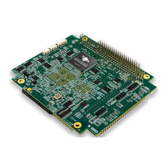
- Page 1 Prodigy /CME PC/104 ® User’s Guide Performance Motion Devices, Inc. 80 Central Street Boxborough, MA 01719 Revision 1.2, December 2009...
- Page 2 NOTICE This document contains proprietary and confidential information of Performance Motion Devices, Inc., and is pro- tected by federal copyright law. The contents of this document may not be disclosed to third parties, translated, copied, or duplicated in any form, in whole or in part, without the express written permission of PMD.
- Page 3 Performance Motion Devices, Inc. (PMD) reserves the right to make changes to its products or to discontinue any product or service without notice, and advises customers to obtain the latest version of relevant information to verify, before placing orders, that information being relied on is current and complete.
- Page 4 Related Documents ® Magellan Motion Processor User’s Guide Complete description of the Magellan Motion Processor features and functions with detailed theory of its operation. ® Magellan Motion Processor Programmer’s Command Reference Descriptions of all Magellan Motion Processor commands, with coding syntax and examples, listed alpha- betically for quick reference.
-
Page 5: Table Of Contents
Table of Contents Chapter 1. Installation ............. 9 Prodigy Family Overview . - Page 6 This page intentionally left blank. Prodigy/CME PC/104 User’s Guide...
- Page 7 List of Figures Prodigy/CME PC/104 Card Component Location, front view ......15 Prodigy/CME PC/104 Card Component Location, back view ......15 Switch settings .
- Page 8 This page intentionally left blank. viii Prodigy/CME PC/104 User’s Guide...
-
Page 9: Chapter 1. Installation
1.Installation In This Chapter Prodigy Family Overview Prodigy/CME PC/104 Card Types Software Accessory Products Installation Sequence Recommended Hardware Software Installation Preparing the Card for Installation Connection Summary Applying Power First-Time System Verification ... -
Page 10: Prodigy/Cme Pc/104 Card Types
Installation Prodigy/CME PC/104 Card Types This manual provides a complete User’s Guide for the Prodigy/CME PC/104 cards. For documentation on other members of the Prodigy Family please consult the appropriate documentation. Prodigy/CME PC/104 cards come in four different configurations depending on the number of axes supported on the card (from 1 to 4). - Page 11 Installation 1.3.1 Pro-Motion Pro-Motion is a sophisticated, easy-to-use exerciser program which allows all card parameters to be set and/or viewed, and allows all card features to be exercised. Pro-Motion features include: • Motion oscilloscope graphically displays processor parameters in real-time •...
-
Page 12: Accessory Products
Installation The C-Motion Engine development tools are described in the C-Motion Development Tools Manual. 1.3.4 VB Motion VB-Motion provides a complete set of methods and properties for developing applications in Visual Basic using a dynamically loaded library (DLL) containing PMD library software. The DLL may also be used from any language capable of calling C language DLL procedures, but no special software support is provided. -
Page 13: Installation Overview
Installation Component Part Number Description IM-1000 Breakout interconnect module provides convenient jack-screw type terminators for the left and right 50-pin GP Connectors. Used with Cable-2003-01.R. IM-600 Breakout interconnect module provides convenient jack-screw type terminators for the 50-pin Option Connector. Used with Cable-2003-01.R. Adapt-USB232-01.R This adapter provides USB to serial conversion. -
Page 14: Software Installation
Installation Two GP Connector cable (PMD p/n Cable-2003-01.R, 50-pin ribbon cable) will be required, and for brushless DC motors as well as step motors driven in microstepping mode, a third Cable-2003-01.R will be required connected to the card’s Option Connector. See Section 4.3, “Connections Summary—Motor Amplifiers,”... - Page 15 Installation bottom. These items are listed in the table below. Connectors and user-adjustable components are located both on the front and the back side of the card, so be sure to double check the orientation of the diagram to locate components. Ethernet Figure 1-1: LEDs...
- Page 16 Installation Label Located Description back side Motor output configuration front side Extension Connector back side Reserved J3, J4 back side Synch Connectors J5, J6 front side Right and Left Connectors front side Option Connector front side Pulse & Direction Connector front side Ethernet Connector front side...
-
Page 17: Connection Summary
Installation Figure 1-3: Switch settings Connection Summary 1.9.1 Motor Connections The following sections summarize the recommended connections for various motor types. DC brush, brushless DC, microstepping, and step (pulse & direction) motors may be connected to the same card, so motor type is allowed to be different on a per-axis basis. - Page 18 Installation Brushless DC Motors The following table summarizes connections to the Prodigy/CME PC/104 cards when brushless DC motors are used. Between one and four axes may be connected, depending on the specific Prodigy card and application requirements. Connections are made through GP Connector, J6 and Option Connector, J5. Both of these connectors are locatable on the card using Figure 1-1 on page 15.
-
Page 19: Serial Port Connection
Installation See Chapter 4, Electrical Reference, on page 69 for a detailed list of connections. Signal Category Signal Description Encoder input signals: (optional per axis) A quadrature channel input B quadrature channel input Index pulse channel input Amplifier output signals: PWM magnitude (phase A) (per axis, if PWM sign, magnitude used) PWM magnitude (phase B) PWM direction (phase A) -
Page 20: 1.10 Applying Power
Installation The communication connections are locatable on the card using Figure 1-1 on page 15. Figure 1-5: Serial and Ethernet Host PC Cable-4355-01.R Cable-4301-01.R Connection Port 2 unused Prodigy/CME Serial Port Port 1 Serial Port Ethernet Port Ethernet Port Cable-4505-01.R Cable-RJ45-02.R 1.9.3 Power Connections... -
Page 21: 1.11 First-Time System Verification
Installation To minimize the risk of unintended machine motion during powerup, care should be taken to control the overall powerup sequence of the Prodigy/CME card and connected system motion amplifiers. The recommended se- quence is to first powerup the Prodigy/CME card, followed by powerup of the motion amplifiers. The time delay to ensure stable operation of the control electronics before powering up the amplifiers varies depending on the system’s power supplies and configuration, but a typical safe figure is 500 mSec - 1,000 mSec. - Page 22 Installation When Pro-Motion is launched you will be prompted with an Interface selection window. A typical screen view when first launching Pro-Motion appears below. 3 Click the Connect icon on the toolbar. Alternatively, on the File menu, click Connect. The purpose of the Interface dialog box is to indicate to Pro-Motion how your Prodigy/CME PC/104 card is connected to the PC.
- Page 23 Installation If serial communication is correctly established, a set of object graphics loads into the Project window to the left, as shown in the following figure. For example for a four axis Prodigy card, you see the card name next to an icon of a card, and below that you see four axis icons, one for each available axis of the motion card.
- Page 24 Installation 1.11.2 Changing the Ethernet Parameters of the Prodigy/CME PC/104 Card To change the Ethernet parameters: 1 With serial communications functioning properly, click the Device toolbar button. The Device window appears. 2 Click Network I/O. The Network I/O Defaults dialog box appears. 3 Click the Ethernet tab.
- Page 25 Installation 1.11.3 Establishing Ethernet Communications The card’s IP Address has now been set, but Pro-Motion does not as yet know what IP address it should use for Ethernet communications to the card. To establish Ethernet communications: 1 Click the Connect toolbar button. 2 Select Ethernet, and then click OK.
- Page 26 Installation 1.11.5 Initializing Motion Axes The next step to verify the correct operation of the system is to initialize each axis of the motion system sequentially, thereby verifying correct amplifier connection, encoder feedback connections (if an encoder is used), and other motion functions.
- Page 27 Installation The Axis Wizard auto tuning routine, which is used with servo motors, is designed to provide stable, but not op- timal, parameters for motion. Pro-Motion provides a wealth of functions including a high speed hardware trace oscilloscope that can assist you in determining optimal servo parameters. Values provided by the axis wizard dur- ing auto tuning may or may not be safe for your system, and it is up to the user to determine if and when they should be used.
-
Page 28: 1.12 Developing User Application Code
Installation 5 Enter motion profiles for deceleration, acceleration, velocity, and destination position (Position 1) that are safe for your system and will demonstrate proper motion. Pro-Motion provides various selectable units for distance and time, but defaults to units of encoder counts (or pulses for step motors) for distance and seconds for time. - Page 29 Installation Figure 1-6: System Two Ways to Host Locate the Controller C-Motion Code on the Engine Prodigy/CME Magellan User PC/104 Card Application Code System Host Controller C-Motion Engine Magellan User Application Code When located on a host controller, the user’s code communicates via the Serial, CANbus, or Ethernet link to the Prodigy/CME card.
- Page 30 Installation Environment) and walks you through an example session resulting in code being downloaded and executed on the Prodigy/CME PC/104 card. Prodigy/CME PC/104 User’s Guide...
-
Page 31: Chapter 2. Operation
2.Operation In This Chapter Card Function Summary Magellan Motion Processor Functions Magellan-Controlled Functions C-Motion Engine Functions Communications Functions General Card Functions Signal Processing and Hardware Functions Software Libraries The Prodigy/CME PC/104 products are high-performance card-based motion controllers for DC brush, brushless DC, pulse &... -
Page 32: Card Function Summary
Operation Figure 2-1: Prodigy/CME PC/104 Card Internal Block Diagram Card Function Summary The Prodigy/CME PC/104 card functions can be broken down into six overall categories: Magellan Motion Processor functions - These are user-accessible functions which reside in the Magellan Motion Processor. - Page 33 Operation Signal processing & hardware functions - A substantial portion of the card performs signal conditioning and other functions associated with safety-related signal processing. These functions are a fixed feature of the card and are not user-accessible. Communications functions - The Prodigy/CME PC/104 card provides sophisticated resource addressing capabilities which allow an external host controller, or the onboard C-Motion Engine, to address various on-card and card-connected resources.
-
Page 34: Magellan Motion Processor Functions
Operation Prodigy/CME card users who write their own software drivers from scratch will need to become familiar with the details of the PRP system and other aspects of card access. The majority of users however will prefer to use C- Motion or VB-Motion, which already encapsulate the details of the card access protocol, and provide convenient and easy to use C and BASIC-callable routines to access the card. - Page 35 Operation Magellan instructions are encoded in packets, which are sent to and from the Magellan Motion Processor. The Magellan processes these packets, performs requested functions, and returns requested data. Within the Prodigy/ CME PC/104 card, the Magellan uses its high-speed parallel-word communications mode to connect to the card's communications bus, which allows the Magellan to be controlled via the C-Motion Engine, or via an external host controller connected to the Prodigy/CME PC/104 card by serial, CANbus, or Ethernet port.
-
Page 36: Magellan-Controlled Functions
Operation 2.2.2 Connections & Associated Signals The Prodigy/CME PC/104 card’s Magellan Motion Processor has extensive signal connections associated with it to allow interfacing to various motion peripherals. See the Magellan Motion Processor User’s Guide as well as Section 2.7, “Signal Processing and Hardware Functions,” on page 52 for a complete description of the signals managed by the Magellan Motion Processor. - Page 37 Operation The eight inputs and eight outputs are read using the Magellan Motion Processor’s ReadIO command and written using the WriteIO command, with an I/O address of 0. This is illustrated in the following table, along with the bit locations of the input and output signals. Address Location Signals...
- Page 38 Operation is used with an address of 1. An amplifier enable signal will be changed only if the corresponding change mask bit is set. The change mask bits are bits 8 – 11, the values to be loaded are bits 0 – 3. Examples WriteIO Address1, 0x0505 // write 0x0505 to I/O Address 1 to enable Amplifiers 1 &...
- Page 39 Operation 2.3.4 Card Watchdog Timer To enhance the overall safety of the card, a watchdog function has been included. When enabled, the watchdog will automatically trigger a card reset if communication to it should be lost. See Section 2.6.2, “Reset,” on page 50 for a description of the actions and signal changes that occur after a card reset.
- Page 40 Operation Example To determine that a reset has occurred, and to determine the cause of the reset, the command ReadIO is used. Assuming that a watchdog timer event has occurred, the value returned would be 0x8000. To clear the reset monitor word, the command WriteIO is sent to address 2 with a value of zero (0).
-
Page 41: C-Motion Engine Functions
Operation Figure 2-2: On-card Dual- ported Memory Dual-ported RAM Magellan Motion (trace buffer) To communication bus Processor Access via 64 KB Magellan Command Packets Access via PRP messages To communication bus The dual-ported RAM trace buffer is a powerful feature that allows various Magellan Motion Processor parameters and registers to be continuously captured and stored to a memory buffer. - Page 42 Operation • Extend the functionality of the Magellan Motion Processor with higher level functions such as contouring, macros, or other complex behaviors • Lower system cost by combining a motherboard function with a dedicated motion card function in a single-card format. 2.4.1 C-Motion Engine Hardware Configuration The C-Motion Engine is a self-contained module that provides non-volatile RAM space to store downloaded user...
- Page 43 Operation that should be observed during run time operation of downloaded C-Motion code. The table above provides these numerical limits. For user downloaded code that does not correctly observe these limits, or for files that have become corrupted, there are a number of fault conditions that can occur while the C-Motion Engine is executing downloaded user application code.
- Page 44 Operation Robot Arm” command sent by the host controller, and then send a series of commands to the Magellan Motion Processor to execute this motion sequence. At the end of the motion sequence the user application code might send an “Arm Extended” message confirming the movement sequence has completed. One method of achieving this is to use the Prodigy/CME PC/104 card’s peripheral mechanism described in Section 3.2.1, “Peripheral Connections,”...
-
Page 45: Communications Functions
Operation 2.4.7 Downloading and Verifying User Application Code The C-Motion Engine development system is used to create, compile, and download user application code. The development system can download the file image for the current code project being worked on, or a specific named file can be downloaded. - Page 46 Operation 2.5.1 PC/104 Bus Communications Prodigy/CME PC/104 cards support the PC/104 bus interface, which uses the ISA (Industry Standard Architecture) electrical interface. In the ISA bus scheme, card addressing is specified manually, via jumpers or switches on each slave card. The Prodigy/CME PC/104 card serves as the ISA bus master, and thus does not have any settable address switch settings.
- Page 47 Operation Settings & default values for Serial 1 and Serial 2: Parameter Range Serial 1 Default Serial 2 Default Baud rate 1200 to 460,800 57,600 115,200 Parity none, even, odd none none # Data bits 5, 6, 7, 8 # stop bits 1, 2 To create a serial port peripheral connection, the above parameters are specified in the PRP action Open...
- Page 48 Operation 2.5.4 Ethernet Communications The Prodigy/CME PC/104 cards support two different Ethernet protocols, TCP (Transmission Control Protocol) and UDP (User Datagram Protocol). TCP is typically used for secure communications to the card, while UDP is typically used for non-critical applications such as data logging, or for the Pro-Motion console window. See Section 2.4.6, “Debug Console Window,”...
- Page 49 Operation Note that all of these functions are handled automatically by the Prodigy/CME card’s TCP processing system, and should in turn also automatically be handled by the host’s TCP system. No user action is required to initiate or mon- itor these automatic TCP ‘keep-alive’ messages. To change the default value of the keep-alive idle time a command is sent to the Device...
-
Page 50: General Card Functions
Operation General Card Functions 2.6.1 Connection Check When sent to the Device resource, this PRP action performs a basic connection check to the Prodigy/CME PC/104 card. A return without a PRP error code indicates that the Prodigy/CME PC/104 card is accessible and processing commands. - Page 51 Operation Parameter Factory default value RS485 duplex Full CANbus Communications Baud Rate 1,000,000 Send Address 0x580 Receive Address 0x600 Task Control & User Application Code Auto start (y/n) Console channel Serial 2 To change the default values used by the card the PRP action sent to the Device resource is used.
-
Page 52: Signal Processing And Hardware Functions
Operation much longer, up to several 100 mSec. Read speed is the same as for other Memory resources, and takes just a few nanoseconds. As for the dual-ported RAM, byte-size memory operations are not supported by the non-volatile memory. The smallest memory unit that can be accessed is 16 bits. The non-volatile memory can be rewritten a limited number of times. - Page 53 Operation The encoder-processing circuitry provides a multi-stage digital filter of the QuadA, QuadB , and Index signals for each axis. This provides additional protection against erroneous noise spikes, thus improving reliability and motion integrity. These signals are named QuadA1+ through QuadB4- (16 signals), and Index1+...
-
Page 54: Software Libraries
Operation 2.7.4.1 Connections & associated signals Both single-ended and differential line driver versions of these signals are output from the Prodigy/CME PC/104 card. There are no associated connections required for these signals to function properly, however, one or more of the digital grounds must be connected. - Page 55 Operation 2.8.1 C Language Code Running on the C-Motion Engine One of the most powerful features of the software libraries provided for the Prodigy/CME PC/104 card is that the code sequence used to accomplish a specific function such as accessing the dual-ported RAM, or sending commands to the Magellan Motion Processor, does not change whether the code is compiled for execution on the host controller, or for execution on the C-Motion Engine.
- Page 56 Operation This page intentionally left blank. Prodigy/CME PC/104 User’s Guide...
-
Page 57: Chapter 3. Accessing Card Resources
3.Accessing Card Resources In This Chapter Resource Addressing Accessing the Communications Ports Accessing On-Card Resources Accessing Magellan-Attached Devices PRP Communication Formats Resource Addressing The Prodigy/CME PC/104 card’s various features and capabilities are organized into groups called ‘resources.’ For example, to communicate with the Prodigy/CME PC/104 card’s Magellan Motion Processor, the host controller sends a command to the MotionProcessor... -
Page 58: Outgoing And Returning Prp Header Formats
Accessing Card Resources Outgoing PRP Header Figure 3-1: Outgoing and Version Status code Action Resource Address Returning PRP header formats 2 bits 2 bits 4 bits 3 bits 5 bits Return PRP Header Version Status code Reserved 2 bits 2 bits 4 bits The majority of communications to/from the host controller and the Prodigy/CME PC/104 card use the PRP header. -
Page 59: Accessing The Communications Ports
Accessing Card Resources 3.1.2 PRP Resources The Prodigy/CME PC/104 card supports five different resource types, each of which is identified by a specific Resource ID. In addition each available resource has an Address. The following table summarizes these Resource IDs and Addresses for the on-card Prodigy/CME PC/104 resources: Resource Resource... - Page 60 Accessing Card Resources External communications use this same bus to access the serial, CANbus, or Ethernet communication ports. This means that commands to card resources may originate from outside the card via the serial, CANbus, or Ethernet ports, or internally, via the C-Motion Engine. A powerful feature of the Prodigy/CME PC/104 card’s communication bus is that it can process multiple communication requests simultaneously.
-
Page 61: Example Network Configuration
Accessing Card Resources Example Figure 3-2 on page 61 shows a network configuration. The host controller needs to initiate, send and receive a message to/from a specific device connected on the CANbus port. Figure 3-2: Host Controller Prodigy/CME Example PC/104 Card Network Ethernet/TCP C-Motion... - Page 62 Accessing Card Resources Sending a message to the resource at address 0 has special meaning as the ‘null’ peripheral. This peripheral Peripheral address indicates ‘no peripheral,’ and may be useful in certain situations for disabling console messages, or disabling the Magellan’s event output mechanism. 3.2.2 Managing Automatically Assigned Addresses Although most network configurations are created once and left in place while the machine is operating, there may be...
-
Page 63: Accessing On-Card Resources
Accessing Card Resources Accessing On-Card Resources The most common use of the Prodigy/CME PC/104 card is to process commands to resources located on the card itself. Typically this means communicating with the on-card Magellan Motion Processor, but it can also mean communicating with other Prodigy/CME PC/104 on-card resources such as the dual-ported RAM. -
Page 64: Accessing Magellan-Attached Devices
Accessing Card Resources Note that the PRP message to send a Magellan command packet did not use a sub-action code in the message body, while the Read command sent to the dual-ported RAM did. Whether or not a sub-action is required, and what the codes are for various sub-actions, is action-specific, and sometimes resource-specific. - Page 65 Accessing Card Resources Figure 3-5: Host Controller Prodigy/CME Host Controller PC/104 Card & Magellan- Ethernet/TCP attached C-Motion Magellan Devices Engine PC/104 Bus Prodigy Card In this ‘bridge’ configuration, the host controller (or the Prodigy/CME PC/104 card’s C-Motion Engine) can access the PC/104-connected Prodigy card very similarly to the way in which the on-card Magellan is addressed.
-
Page 66: Prp Communication Formats
Accessing Card Resources PRP Communication Formats The following sections discuss how PRP messages should be formatted on the Serial, CANbus, and Ethernet networks so that they can be properly interpreted by the Prodigy/CME PC/104 card. Note that PRP messages from a host are not sent over the PC/104 bus, because the Prodigy/CME PC/104 card acts as the bus master. - Page 67 Accessing Card Resources 3.5.2 PRP Messages over CANbus If the Prodigy/CME PC/104 card is set up to process PRP command messages from a host controller over CANbus, a specific format for the packets must be followed. This section describes the format of how PRP messages are carried over CANbus.
- Page 68 Accessing Card Resources This page intentionally left blank. Prodigy/CME PC/104 User’s Guide...
-
Page 69: Chapter 4. Electrical Reference
4.Electrical Reference In This Chapter User-Settable Components Connectors Connections Summary—Motor Amplifiers Cables Environmental and Electrical Ratings Mechanical Dimensions User I/O memory Map User-Settable Components Figure 4-1 illustrates the locations of the principal components of the Prodigy/CME PC/104 cards. The user-settable components of the card are listed in the following table: Component Function... - Page 70 Electrical Reference Figure 4-2: Prodigy/CME PC/104 Card Component Location, back view 4.1.1 Encoder Connections and Resistor Packs Encoder inputs may be connected differentially, with two wires for QuadA QuadB , and Index signals, or with just one wire per signal. If differential connections are being employed, resistor packs RS1, RS2, and RS3 should remain installed.
-
Page 71: Switch Settings By Output Type
Electrical Reference Encoder connections when using single-ended encoder input: Signal J5 & J6 (GP Connector) Pin Connections Axis 1 Axis 2 Axis 3 Axis 4 QuadAn J5-1 J5-19 J6-1 J6-19 QuadBn J5-3 J5-21 J6-3 J6-21 Indexn J5-5 J5-23 J6-5 J6-23 J5-7 J5-25 J6-7... -
Page 72: Connectors
Electrical Reference Connectors There are 11 user-accessible connectors on the Prodigy/CME PC/104 card. See Figure 4-1 on page 69 for the specific locations of the connectors on the card. The connectors and their functions are outlined in the following table: Connector Name Connector # Functionality... - Page 73 Electrical Reference 4.2.2 GP Connector Using DC Brush Motors Connection Description Connection Description QuadA1+ Quadrature A+ encoder input (axis 1) QuadA3+ Quadrature A+ encoder input (axis 3) QuadA1- Quadrature A- encoder input (axis 1) QuadA3- Quadrature A- encoder input (axis 3) QuadB1+ Quadrature B+ encoder input (axis 1) QuadB3+...
- Page 74 Electrical Reference 4.2.3 GP Connector Using Brushless DC or Microstepping Motors Connection Description Connection Description QuadA1+ Quadrature A+ encoder input (axis 1) QuadA3+ Quadrature A+ encoder input (axis 3) QuadA1- Quadrature A- encoder input (axis 1) QuadA3- Quadrature A- encoder input (axis 3) QuadB1+ Quadrature B+ encoder input (axis 1) QuadB3+...
- Page 75 Electrical Reference 4.2.4 GP Connector Using Step (Pulse & Direction) Motors Connection Description Connection Description QuadA1+ Quadrature A+ encoder input (axis 1) QuadA3+ Quadrature A+ encoder input (axis 3) QuadA1- Quadrature A- encoder input (axis 1) QuadA3- Quadrature A- encoder input (axis 3) QuadB1+ Quadrature B+ encoder input (axis 1) QuadB3+...
- Page 76 Electrical Reference 4.2.5 Option Connector When the Prodigy/CME PC/104 card is used with either brushless DC or microstepping motors, the Option Connector (labeled J9 in Figure 4-1 on page 69) provides additional signals for multi-phase motor output and input of signals such as Hall sensors. The Option Connector is a 50-pin header-style connector. Connection Description Connection...
-
Page 77: Sync I/O Connector To Three Cards
Electrical Reference Connection RS232 RS485 Full Duplex RS485 Half Duplex Ground Ground Ground 4.2.7 Sync I/O Connector The two Sync I/O connectors located on the Prodigy/CME PC/104 card (J3 and J4 in Figure 4-1 on page 69) allow for the synchronization of multiple Prodigy/CME PC/104 cards within a single system. This configuration enables operation within the same cycle period. - Page 78 Electrical Reference Signal Description Pin Number CAN+ Positive CAN signal connection no connect reserved, do not connect CAN- Negative CAN signal connection no connect reserved, do not connect CAN- Negative CAN signal connection (either this signal or signal 4 can be used for CAN-) Ground termination optional termination - connecting this pin...
- Page 79 Electrical Reference Number Signal Number Signal axis 4, pulse - axis 1, pulse - axis 1, direction + axis 2, direction + axis 1, direction - axis 2, direction - axis 4, direction + axis 3, pulse + axis 4, direction - axis 3, pulse - axis 2, pulse + axis 2, pulse -...
-
Page 80: Connections Summary-Motor Amplifiers
Electrical Reference Connections Summary—Motor Amplifiers The Prodigy/CME PC/104 card supports four methods of output to motor amplifiers, as described in the following table: Motor Output Method Signal Output Analog signals from the onboard D-A converters. PWM sign-magnitude Pulse width modulated signals with separate magnitude and sign signals per output phase. PWM 50/50 Pulse width modulated square-wave signals with a single PWM signal per output phase. - Page 81 Electrical Reference PWM 50/50 PWMMag1-4A PWM phase 1 J9-1 J9-6 J9-11 J9-16 PWMMag1-4B PWM phase 2 J9-2 J9-7 J9-12 J9-17 PWMMag1-4C PWM phase 3 J9-3 J9-8 J9-13 J9-18 Ground J9-5 J9-10 J9-15 J9-20 * Names of amplifier connections vary. Common names are shown. 4.3.3 Microstepping Motor Connections To connect to step motors in microstepping mode, two sinusoidal phase signals are driven per axis via the Option...
-
Page 82: Cables
Electrical Reference Cables The following table provides a summary of the standard cable accessories available with Prodigy/CME PC/104 cards. Component Part Number Description PW-2001-KIT-01.R Power Supply & cable set. This is a US Domestic & International wall adapter power sup- ply and associated cable that plugs into the Prodigy/CME PC/104 card and provides power through its Power Connector. - Page 83 Electrical Reference 4.4.2 Cable-2003-01.R PMD Part #: Cable-2003-01.R Description: 50-pin connector to 50-pin connector ribbon cable. Length: 3.0 feet Cable: 50 pair, 30 AWG, shielded round Wiring: Straight through 4.4.3 Cable-4301-01.R PMD Part #: Cable-4301-01.R J17 Pin Signal Connects to Description: 10-pin dual header (J17) to DB-9 cable RS485Rcv Length: 1.0 feet...
- Page 84 Electrical Reference 4.4.5 Cable-4701-01.R PMD Part #: Cable-4701-01.R Connects J16 Pin Signal Description: 8-pin dual header to RJ45 cable no connect Length: 1.0 feet CAN+ Cable: 4 conductor, 24 AWG, twisted no connect no connect Wiring: See table. CAN- no connect no connect CAN- no connect...
-
Page 85: Environmental And Electrical Ratings
Electrical Reference 4.4.9 Cable-4505-01-R PMD Part #: Cable-4505-01.R J16 Pin Signal Connects to: Description: 10-pin dual header to RJ45 cable EthernetTx+ 1 Length: 5.0 feet EthernetTx- Cable: 4 pair, 24 AWG, Cat 5/5e EthernetRx+ 3 Wiring: See table. no connect no connect EthernetRx- no connect... -
Page 86: Mechanical Dimensions
Electrical Reference Mechanical Dimensions Figure 4-5: Prodigy/CME mechanical dimensions User I/O Memory Map The Magellan Motion Processor reserves the sector from address 1000h to 10FFh in peripheral space for user-defined I/O devices. The Prodigy/CME PC/104 card uses this sector as shown in the following table: Address Device Description... - Page 87 Electrical Reference Address Device Description 1020h - 10CFh None Available for use with custom peripherals over Extension Connec- 10D0h - 10DAh Reserved 10DBh Build register Build number of Prodigy FPGA 10DCh - 10DFh Reserved 10E0h - 10EFh None Available for use with custom peripherals over Extension Connec- 10F0h - 10FDh Reserved 10FEh...
- Page 88 Electrical Reference This page intentionally left blank. Prodigy/CME PC/104 User’s Guide...
-
Page 89: Chapter 5. Interconnect Module
5.Interconnect Module In This Chapter IM-1000 Interconnect Module IM-600 Interconnect Module DC-1000 SSI Option Card IM-1000 Interconnect Module The IM-1000 is an interconnect module which assists in the set up and configuration of Prodigy/CME PC/104 cards, and also provides complete options for external connections. All wiring to and from the Prodigy/CME PC/104 card, the amplifiers, power supplies, IOs and encoder feedback may easily be connected to this central point. - Page 90 Interconnect Module Connector Description 100-position connector OPTO22 connector 50-position connector 50-position connector External hardware reset button Screw terminals (3) 100-terminal connection blocks for connecting to one 100-position, or two 50-position cables. The enclosure of the card is a standard Phoenix DIN rail mounting system. Alternatively, the enclosure may be removed, and the card mounted to other systems via the 3.5 mm mounting holes located on the corners of the card.
-
Page 91: Im-600 Interconnect Module
Interconnect Module Prodigy/CME PC/104 IM-1000 Description J5/J6 J6-45 AmpEnable4 J6-13 AxisOut1 J6-30 AxisOut2 J6-13 AxisOut3 J6-30 AxisOut4 All even-numbered pins IM-600 Interconnect Module The IM-600 is an interconnect module which assists in the set up and configuration of the Option Connector and the Pulse &... -
Page 92: Dc-1000 Ssi Option Card
Interconnect Module wired ‘straight through’ from the connector input, so that the documentation for the Prodigy card connectors or cable headers can be conveniently used to determine correct pin placement on the IM-600’s jack screw pin connections: Prodigy Card Connector & Connect to Screw terminal connections &... - Page 93 Interconnect Module • Compatible with any absolute encoders which support the Synchronous Serial Interface (SSI), such as Haidenhein, Stegmann, Thalheim, and Renishaw encoders that meet the DC-1000’s resolution and clock frequency requirements Unlike incremental encoders, optical encoders always supply the exact absolute position. At power-on, the encoder will report its exact position.
- Page 94 Interconnect Module Figure 5-3: DC-1000 location of components [59.0] 2.32 KEY: [mm] inch [69.0] 2.72 The names and descriptions of the main components of the DC-1000 are detailed in the following table: Label Name Description Parallel connector This socket connects to the parallel input connector of the Prodigy/CME PC/104 card.
- Page 95 Interconnect Module IDC Pin No. Description Axis +5 or +12 VDC to Encoder Clock 3+ Clock 3- DIN 3+ DIN 3- +5 or +12 VDC to Encoder Clock 4+ Clock 4- DIN 4+ DIN 4- The settings for the jumper (labeled JP1 in Figure 5-3 on page 94) are outlined in the following table: Pins Jumpered Setting 1 - 2 12V DC...
- Page 96 Interconnect Module 2 Position the DC-1000’s parallel connector socket (DC1) over the Prodigy/CME PC/104 card’s Extension Connector. Ensure that the top edge of the mating connectors are aligned. The DC1 connector socket is shorter than the Prodigy/CME PC/104 card’s Extension Connector, and when the top edges of both are properly aligned, three sets of pins on the Extension Connector will be visible at the bottom of the DC- 1000’s connector when viewed from above the cards.
- Page 97 Interconnect Module 5.3.5 DC-1000 Software Commands The DC-1000 may be operated in mixed-mode. Any or all of the four axes may be configured in any combination of incremental or absolute modes. The following commands are required to configure the absolute encoder mode for the DC-1000.
- Page 98 Interconnect Module This page intentionally left blank. Prodigy/CME PC/104 User’s Guide...
-
Page 99: Index
Index Numerics CAN serial communication physical layer 77 100-terminal connection blocks 90 CANbus packet processing 67 26-position IDC connector 93 card 40-position mating connector 93 function summary 32 50-position connector 90 types 10 C-Motion 11, 14 engine development environment 11 absolute mode 97 engine development environment features 11 accessing... - Page 100 cards 74 encoder 72 motor connections 18, 81 connections 70 modulus settings 97 feedback 89 motion processor reset 39 inputs 70 motor mating connector 93 amplifier output methods 80 resolutions 93 axis 80 settings 69 output configuration 16 signals 70 output method 80 environmental and electrical ratings 85 multi-phase...
- Page 101 resources 59 software PRP messages commands, DC-1000 97 CANbus 67 libraries 54 Ethernet 67 packages 10 over serial 66 SSI 78 pulse & direction 53 step (pulse & direction) motor connections 81 cards 75 storage temperature 85 pulse and direction differential output connector 78 supply voltage limits 85 pulse and direction outputs 78 sync I/O 77...
- Page 102 This page intentionally left blank. Prodigy/CME PC/104 User’s Guide...
- Page 103 For additional information, or for technical assistance, please contact PMD at (978) 266-1210. You may also e-mail your request to support@pmdcorp.com Visit our website at http://www.pmdcorp.com Performance Motion Devices 80 Central Street Boxborough, MA 01719 Prodigy/CME PC/104 User’s Guide...
Need help?
Do you have a question about the Prodigy Series and is the answer not in the manual?
Questions and answers