
Subscribe to Our Youtube Channel
Related Manuals for Performance Motion Devices Magellan DK58113


Summary of Contents for Performance Motion Devices Magellan DK58113
- Page 1 ® Magellan Motion Control IC DK58113 Developer Kit User Manual Performance Motion Devices, Inc. 1 Technology Park Drive Westford, MA 01886 Revision 1.3, April 2021...
- Page 2 NOTICE This document contains proprietary and confidential information of Performance Motion Devices, Inc., and is pro- tected by federal copyright law. The contents of this document may not be disclosed to third parties, translated, copied, or duplicated in any form, in whole or in part, without the express written permission of PMD.
- Page 3 “Unauthorized Applications” and use of a Performance Motion Devices, Inc. product in such a system would not be warranted or approved by Performance Motion Devices, Inc.
- Page 4 Related Documents ® Magellan Motion Control IC User Guide Complete description of the Magellan Motion Control IC features and functions with detailed theory of its operation. MC58113 Electrical Specifications Information on physical and electrical characteristics, timing diagrams, pin descriptions, application notes and application schematics of MC58113 IC.
-
Page 5: Table Of Contents
Table of Contents 1. Installation ....................7 1.1 Introduction ............................7 1.2 Magellan Motion Control IC Family Overview ................ 8 1.3 Developer Kit Components List ....................9 1.4 DK58113 Board........................... 9 1.5 Included Accessories........................10 1.6 Installation Overview ........................10 1.7 Recommended Hardware ...................... - Page 6 This page intentionally left blank. DK58113 Developer Kit User Manual...
-
Page 7: Installation
1.Installation In This Chapter Introduction Magellan Motion Control IC Family Overview Developer Kit Components List DK58113 Board Included Accessories Installation Overview Recommended Hardware Software Installation Preparing the Board for Installation Connection Summary ... -
Page 8: Magellan Motion Control Ic Family Overview
Installation Magellan Motion Control IC Family Overview The following table presents a feature summary of the products in the Magellan Motion Control IC product family: M C 5 8 0 0 0 S e r i e s M C 5 5 0 0 0 S e r i e s M C 5 8 11 3 S e r i e s ( E x c e p t M C 5 8 11 3 ) # of axes... -
Page 9: Developer Kit Components List
Installation M C 5 8 0 0 0 S e r i e s M C 5 5 0 0 0 S e r i e s M C 5 8 11 3 S e r i e s ( E x c e p t M C 5 8 11 3 ) Chipset configurations MC58420 (4 axes, 2 ICs) MC55420 (4 axes, 2 ICs) -
Page 10: Included Accessories
Installation • Compact 3.3" x 4.7" standalone form factor (8.4 cm x 11.9 cm) Included Accessories The DK58113 includes various accessories that you may find useful: Component PMD Part Description Number Cable-USB-DB9 USB to 9-pin serial cable. This cable connects to the DK58113’s DB-9 serial port and to the PC's USB port. -
Page 11: Software Installation
Installation • Intel (or compatible) processor, 1 Gbyte of available disk space, 256 MB of available RAM, and a CD ROM drive. The supported PC operating systems are Windows XP, Vista, Windows 7, and Windows 8. • One step, DC brush, or brushless DC motor. This motor may or may not provide encoder position feedback signals, depending on the type of motor being used. - Page 12 Installation 1.8.1 Pro-Motion Pro-Motion is a sophisticated, easy-to-use exerciser program which allows all Magellan IC parameters to be set and/ or viewed, and allows all features to be exercised. Pro-Motion features include: • Motion oscilloscope graphically displays processor parameters in real-time •...
-
Page 13: Preparing The Board For Installation
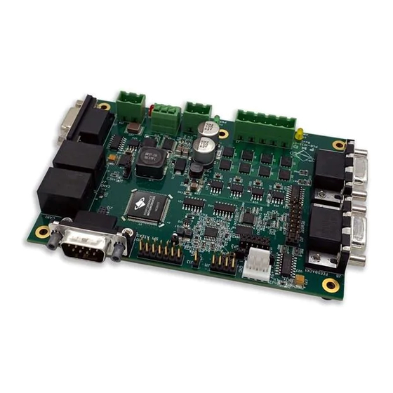
Installation VB Motion is documented in the PMD Resource Access Protocol Programming Reference. Preparing the Board for Installation Figure 1-1 shows the location of various on-card components such as connectors and jumpers. SPI Atlas Figure 1-1: +5V Power Host SPI Synch Remote Amplifier Connector... -
Page 14: Connection Summary
Installation However, for reference the table below shows the available jumper settings of the DK58113 board: Factory Default Jumper ID Setting Setting &Description JP1, JP2 1-2 (on-card amplifier) Installing jumpers at 1-2 for JP1 and JP2 configures the DK58113 for operation of the on-card amplifier. Installing jumpers at 2-3 for JP1 and JP2 disables the on- board amplifier, and configures the DK58113 for operation with a user-designed amplifier via the J12... - Page 15 Installation HV Power Amplifier Figure 1-3: Connector Signal Connector DC Brush Enable Motor Connection Motor Overview Drive Connector DC Brush Motor Motor A Serial MC58113 CANbus Brush MC51113 Amplifier Host I/O Motor B Axis 1 Home, limits, and Encoder Feedback Feedback Connector Motor Power...
- Page 16 Installation Pin # Signal Name Description Index1- Differential Index- quadrature input. optional for step motor axes Hall1A Hall signal input phase A. not used for DC Brush or step motors Hall1B Hall signal input phase B. not used for DC Brush or step motors Hall1C Hall signal input phase C.
-
Page 17: Applying Power
Installation Motor type DK58113 Motor Lead Motor Coil Connections Step motor MotorA phase A+ winding connection MotorB phase A- winding connection MotorC phase B+ winding connection MotorD phase B- winding connection Case/shield (optional) shield connection Shield connections to the motor are strongly recommended. Not connecting the shield signal may result in in- creased EMI (electromagnetic interference), reduced immunity to ESD (electro static discharge), or electrical noise resulting in motor operation failure. -
Page 18: First-Time System Verification
Installation 1.12 First-Time System Verification The first time system verification procedure summarized below has two overall goals. The first is to connect the DK58113 board with the PC that is being used so that they are communicating properly, and the second is to initialize the axis and bring it under stable control capable of making trajectory moves. - Page 19 Installation 3 Click Serial, and then click OK. The Serial Port dialog box displays with default communication values of 57,600 baud, no parity, 1 stop bit, and point to point protocol. 4 Click OK without changing any of these settings. If serial communication is correctly established, a set of object graphics loads into the Project window to the left, as shown in the following figure.
- Page 20 Installation The Axis Wizard initialization window appears. 3 Click Next and follow the Axis Wizard instructions for each page of the axis initialization process. A typical Axis Wizard sequence takes 5-10 minutes. Important! In addition to application specific parameters you will need to enter various control parameters during Axis Wizard setup to safely control the board.
- Page 21 Installation 1 Click the Trajectory button in the Axis Control window. The Trajectory dialog box appears. 2 In the Profile mode list, select Trapezoidal. 3 Enter motion profiles for deceleration, acceleration, velocity, and destination position (Position 1) that are safe for your system and will demonstrate proper motion. Pro-Motion provides various selectable units for distance and time, but defaults to units of encoder counts (or steps for step motors) for distance and seconds for time.
- Page 22 Installation When restarting Pro-Motion it is important that you restore the configuration that you have saved, particularly the on- card amplifier limits and scale factors established during Axis Wizard setup. Do this by selecting File and Open Project, selecting the correct file previously stored. Operation of the DK58113 without proper safety settings established during Axis Wizard operation may harm the DK58113 board or the application hardware.
-
Page 23: Operation
2.Operation In This Chapter DK58113 Block Diagram Communication Ports Switching Motor Amplifier Drive Protection and Control Signals DC Bus Connecting to a Remote Amplifier Connecting to an Atlas Amplifier Motor Feedback Signals ... -
Page 24: Communication Ports
Operation External Shunt Resistor & Diode Figure 2-1: DK58113 Block DC Bus Current & Voltage Diagram Monitoring DC Bus Switching HV Input Voltage Motor Motor Drive Output Management Amplifier Shunt Analog Signal Conditioning 3.3 V Temperature +5V Input sense Logic Supply (Optional) +15V PWM Commands... - Page 25 Operation Figure 2-2: PC to DK58113 Host PC SPI Connection Summary Cable-6001-II USB-8452 Port USB to NI Module Module Cable DK58113 Card The major components required for PC to DK58113 SPI communications are listed below: Part Item number Manufacturer Description J13 to SPI interface module Cable-6001-01 This cable interconnects the National...
-
Page 26: Switching Motor Amplifier
Operation Switching Motor Amplifier The DK58113 board contains a high-efficiency MOSFET power stage with PWM input control and leg current feedback. A different configuration is used for each motor type: • Brushless DC motors are driven in a 3-phase bridge configuration consisting of 6 MOSFETs and 3 leg current sensors •... - Page 27 Operation PWMHigh1B Digital high side drive output for motor phase B PWMLow1B Digital low side drive output for motor phase B PWMHigh1C Digital high side drive output for motor phase C PWMLow1C Digital low side drive output for motor phase C Current1A Analog input containing the current flow through the low side of the switching bridge for phase A.
- Page 28 Operation PWMLow1B Figure 2-5: Pre- PWMHigh1B driver Two-Phase PWMHigh1A Pre- Step Motor PWMLow1A driver Bridge Configuration Phase A Current1A Analog Analog Conditioning Conditioning Current1B MC58113 MC54113 PWMLow1D Pre- PWMHigh1D driver PWMHigh1C Pre- PWMLow1C driver Phase B Current1C Analog Analog Conditioning Conditioning Current1D As shown in the table below eight PWM output signals and four analog feedback signals interface between the...
- Page 29 Operation connected the value of these settings will likely change, and if an Atlas amplifier is used, other than the motor output mode these parameters do not need to be specified. The following table shows the recommended (or required) settings for amplifier-related parameters: Parameter Value &...
-
Page 30: Drive Protection And Control Signals
Operation Drive Protection and Control Signals 2.4.1 t Current Foldback Protection The MC58113 uses current feedback to implement I t current limiting. This feature protects the on-card amplifier by controlling its ability to operate above specific selected continuous current ratings. When the current loop is enabled and the I t energy limit is exceeded, the MC58113 will automatically fold back the phase currents to a user programmable continuous current limit value. - Page 31 Operation All of the MC58113 parameters described in this section can be conveniently specified using Pro-Motion via the Axis Wizard. See Section 1.12, “First-Time System Verification” for more information. 2.4.2 Overtemperature Protection The DK58113 uses a temperature sensor to continuously monitor the temperature of the on-card power MOSFETs. 2.4.2.1 Converting Temperature Readings into Degrees C The MC58113 IC inputs temperature readings via its Temperature analog input and performs related functions such...
-
Page 32: Dc Bus
Operation DC Bus Figure 2-6: DC Bus Shunt Power Resistor & Diode Monitoring via J14 Circuitry Shunt Pre- driver Analog BusVoltage Signal Conditioning MC581130 Analog BusCurrentSupply Signal Conditioning Switching Motor Bridge Analog Current1A-1D Leg Current Signal Conditioning Sensors Figure 2-6 shows the DC bus monitoring circuitry used with the DK58113 board. - Page 33 Operation 2.5.1.2 DC Bus Current Limits The following MC58113 DC bus current limits are required to safely operate the DK58113 board: Parameter Value & Units Comments Bus Current Supply Limit 20.0 A This value should be entered to ensure safe operation of the DK58113.
-
Page 34: Connecting To A Remote Amplifier
Operation As shown in Figure 2-6 the MC58113 provides a shunt PWM output, which in turn drives a MOSFET switch on the DK58113 board. The resistor connected at J14 should have a resistance such that the current flow through the Shunt MOSFET does not exceed 10 amps. -
Page 35: Connecting To An Atlas Amplifier
Operation Note that connection of the remote amplifiers HV supply to the DK58113 card is optional. Doing so allows use of the DK58113’s over and undervoltage check feature. The DK58113’s on-card amplifier must be disabled via JP1 and JP2 for remote amplifier operation. See Section 1.6, “Installation Overview”... - Page 36 Operation Figure 2-9: Main Encoder Input Circuits 2.8.2 Hall Inputs The input buffer for the Hall A, B and C signals is shown in Figure 2-10. This circuit accepts signals in the range of 0 – 24 V and has TTL compatible, Schmitt trigger thresholds. It has a pull-up to 5V to allow direct interfacing to open collector sources without the need for an external pull-up resistor and an R-C low pass filter to reject noise.
- Page 37 Operation Figure 2-11: Limit and Home Input Circuits 2.8.4 AxisIn and AxisOut Signals The input buffer for the AxisIn signal is shown in Figure 2-12. This circuit accepts signals in the range of 0 – 24 V and has TTL compatible, Schmitt trigger thresholds. It has a pull-up to 5V to allow direct interfacing to open collector sources without the need for an external pull-up resistor and a 13 kHz R-C low pass filter to reject noise.
-
Page 38: Enable And Faultout Signals
Operation Figure 2-13: AxisOut Circuit AxisIn and AxisOut are versatile I/O signals. They are not dedicated to any particular motion control function but can be programmed to implement a wide array of system integration functions. See the Magellan Motion Control IC User Guide for more information on configuring and programming these signals. -
Page 39: Multi-Board Synchronization
Operation The output driver for FaultOut is shown in Figure 2-15. This circuit can continuously sink over 100 mA and source 4mA from a pull-up resistor to 5V. The diode in series with the pull-up resistor allows loads powered from up to 24 VDC to be switched. -
Page 40: On-Ic Nvram Configuration Storage
Operation 2.11 On-IC NVRAM Configuration Storage The MC58113-series ICs provide the ability to directly store configuration information such as gain parameters, drive- related safety parameters, and other parameters. This setup information, once loaded, is automatically initialized into the MC58113's active configuration registers at each power-up. When used in an actual control system the NVRAM may therefore be useful to reduce or eliminate communications to the MC58113 IC during powerup. -
Page 41: Electrical Reference
3.Electrical Reference In This Chapter User-Settable Components Connectors Motor Connection Quick Reference Absolute Maximum Ratings Environmental and Electrical Ratings DK58113 On-Board Amplifier Quick Reference User-Settable Components The following table details the available DK58113 jumper settings, which are the DK58113’s only user-settable hard- ware components: Factory Default Jumper ID... -
Page 42: Connectors
Electrical Reference Connectors SPI Atlas Figure 3-1: +5V Power Host SPI Synch Remote Amplifier Connector Connector Connector DK58113 Connector Enable Jumpers Board Remote Component Amplifier Location Connector CAN1 Axis 1 MC58113 Feedback Connector Connectors CAN2 RS-232/RS485 Selector Jumper Axis 2 Serial Feedback Connector... - Page 43 Electrical Reference Connector Connector Name Description Synch Provides signals that allow synchronization of the MC58113 with external controllers +5V Power Provides logic power to the board when HV Power is not available or is not being used 3.2.1 HV Power Connector (J1) The DK58113 board uses a dedicated 2-pin HV power connector (J1) that accepts input voltage in the range of +12 to 56 VDC.
- Page 44 Electrical Reference Axis 1 Feedback Connector Pin Connection Description J8 - Axis1 Feedback Connector QuadA1+ Axis 1 Quadrature A+ encoder input QuadA1- Axis 1 Quadrature A- encoder input QuadB1+ Axis 1 Quadrature B+ encoder input QuadB1- Axis 1 Quadrature B- encoder input Ground Index1+ Axis 1 Index+ input...
- Page 45 Electrical Reference The following tables show this: Encoder connections when using differential encoder input: J8 - Axis 1 J9 - Axis 2 Feedback Feedback Signal Connector Connector QuadAn+ J8-1 J9-1 QuadAn- J8-2 J9-2 QuadBn+ J8-3 J9-3 QuadBn- J8-4 J9-4 Indexn+ J8-6 J9-6 Indexn-...
- Page 46 Electrical Reference Signal Description no connect AmpSPIClock AmplifierSPIClock signal from MC58113 AmpSPIXmt AmplifierSPIXmt signal from MC58113 3.2.6 Remote Amplifier Connector (J12) This connector provides signals that allow an external switching amplifier to be connected to the DK58113. This connector is not used if the on-card amplifier is used, or if an Atlas amplifier is used. If a remote amplifier is used jumpers JP1 and JP2 must be set to the 2-3 position.
- Page 47 Electrical Reference is generally recommended unless cable lengths are very short and speed is slow. ISO-11898 requires 120 Ohm termination at each end of the bus. Note that it is up to the customer to verify their network topology and operating parameters.
- Page 48 Electrical Reference Signal Description HostSPIStatus This signal indicates when an SPI response is available. Ground Reset Active low reset signal for MC58113 IC. 3.2.11 Synch Connector (J13) This connector provides a synch signal connection which can be used to synchronize the MC58113 with external controllers including other MC58113s.
-
Page 49: Motor Connection Quick Reference
Electrical Reference Label Connector Name Connector Part Number Connector Mate J6, J7 CAN1, CAN2 RJ45 RJ45 connector plug Serial DB-9, female DB-9, male Host SPI 2 by 4 unshrouded header, male, .1" Samtec socket, 8-position, .1’’ spacing. spacing p/n: ISDM-04 Synch 2 position unshrouded header, male, .1"... -
Page 50: Environmental And Electrical Ratings
Electrical Reference Environmental and Electrical Ratings Storage temperature: -40 to +125 degrees C (-40° F to +257°F) Operating temperature: 0 to +70 degrees C (32° F to +158°F) HV power requirement: +12V to + 56V operating range 5.0 A Motor amplifier continuous current limit Motor amplifier peak current limit: 10.0 A Optional +5V requirement:... - Page 51 Electrical Reference Parameter Value & Units Comments Minimum Current Read Time 2,000 nSec To ensure sufficient minimum current read time with BLDC motors this parameter must be set to this value. Leg Current Conversion .733 mA/count This value should be entered so that the leg current can be traced and displayed correctly in amps.
- Page 52 Electrical Reference This page intentionally left blank. DK58113 Developer Kit User Manual...
- Page 53 Index DC bus Symbols /Enable and FaultOut Signals 38 current monitoring 32 /Enable signal 38 overvoltage and undervoltage 33 diagrams Numerics AxisIn circuit 37 3-phase bridge 26 FaultOut circuit 39 main encoder input circuits 36 differential encoder AxisIn and AxisOut signals 37 signals 35 Block Diagram 23 encoder...
- Page 54 main encoder input circuits 36 MOSFET power stages 26, 31 temperature sensors 31 Motor Feedback 35 motor feedback 35 undervoltage, condition and threshold 33 user-settable components 41 networking configurations 24 noise R-C lowpass filter and 36 operating temperature 31 overtemperature protection 31 ports, communication 24 power applying 17...
- Page 55 For additional information, or for technical assistance, please contact PMD at (978) 266-1210. You may also e-mail your request to support@pmdcorp.com Visit our website at http://www.pmdcorp.com Performance Motion Devices 55 Old Bedford Rd. Lincoln, MA 01773 DK58113 Developer’s Kit User’s Manual...
- Page 56 This page intentionally left blank. DK58113 Developer’s Kit User’s Manual...
Need help?
Do you have a question about the Magellan DK58113 and is the answer not in the manual?
Questions and answers