
Related Manuals for Raven SmarTrax MD Series

Summary of Contents for Raven SmarTrax MD Series
- Page 1 Case IH AFX/X230 Combines, Windrower WD/WDX & New Holland CR/CX Combines, Windrower H/HW Series SmarTrax™ MD Installation Manual P/N 016-5030-051 Rev. B 11/15 E26359 Copyright 2014, 2015...
-
Page 3: Table Of Contents
Table of Contents Chapter 1 Important Safety Information..........1 Electrical Safety ........................2 Chapter 2 Introduction................3 Preparing for Installation ......................4 Recommendations ......................4 Point of Reference ....................... 4 Updates ............................. 4 Kit Contents ..........................5 Chapter 3 Mechanical Drive Installation ..........9 Disassemble the Mechanical Drive Spline Assembly .............. - Page 4 Table of Contents Case IH AFX/X230 Combines, Windrower WD/WDX & New Holland CR/CX Combines, Windrower H/HW Series SmarTrax™ MD Installation Manual...
-
Page 5: Important Safety Information
• Follow all safety information presented within this manual. • If you require assistance with any portion of the installation or service of your Raven equipment, contact your local Raven dealer for support. • Follow all safety labels affixed to the SmarTrax MD system components. Be sure to keep safety labels in good condition and replace any missing or damaged labels. -
Page 6: Electrical Safety
Chapter 1 CAUTION Electrical Safety • Always verify that the power leads are connected to the correct polarity as marked. Reversing the power leads could cause severe damage to the equipment. • Ensure that the power cable is the last cable to be connected. Case IH AFX/X230 Combines, Windrower WD/WDX &... -
Page 7: Introduction
I ntroduction CHAPTER C h a p t e r 2 Congratulations on your purchase of the SmarTrax™ MD system! SmarTrax MD-assisted steering takes the stress out of driving and makes it quick and easy for you to improve your operating efficiency and performance. SmarTrax MD is compatible with Cruizer II™ and Cruizer II™ RTK, Envizio Pro™, Envizio Pro®, Envizio Pro XL™, and Viper Pro™... -
Page 8: Preparing For Installation
Software and manual updates are available on the Raven Applied Technology website: http://www.ravenhelp.com At Raven Industries, we strive to make your experience with our products as rewarding as possible. One way to improve this experience is to provide us with feedback on this manual. -
Page 9: Kit Contents
Raven dealer. Important: Modification/alteration of any part in the SmarTrax MD system or the use of any non-Raven approved parts will void the warranty on the system. Raven Industries assumes no liability for using modified, altered, or non-Raven approved parts or components. - Page 10 Chapter 2 SmarTrax MD Installation Kit (P/N 117-5030-051) TABLE 1. Picture Item Description Part Number Qty. Bearing - 1/2” Plastic Flanged 325-0000-036 Bolt - #10-24 x 3/4” UNC Zinc Carriage 311-0069-082 Screw - #10-24 x 3/4” Socket Head Cap 311-0068-051 Nut - 3/8”-16 Zinc Flanged Lock 312-1001-167 Nut - #10-24 Wing...
- Page 11 Introduction SmarTrax MD Controller Kit (P/N 117-5030-020) TABLE 2. Picture Item Description Part Number Qty. Cable - SmarTrax MD Node Harness 115-4001-157 Switch - Foot 063-0173-593 P/N 016-5030-051 Rev. B...
- Page 12 Chapter 2 Case IH AFX/X230 Combines, Windrower WD/WDX & New Holland CR/CX Combines, Windrower H/HW Series SmarTrax™ MD Installation Manual...
-
Page 13: Mechanical Drive Installation
M echanical Drive CHAPTER C h a p t e r 3 Installation Disassemble the Mechanical Drive Spline Assembly Spline Assembly Disassembled FIGURE 1. Washer Female Spline Adapter Bolts Male Spline Adapter Locate the 7/8” 36 tooth spline adapter assembly (P/N 063-4001-024). Disassemble the spine adapter assembly as shown in Figure 1 above. - Page 14 Chapter 3 Steering Wheel Cap FIGURE 2. Remove the cap from the center of the steering wheel. Nut to be Removed FIGURE 3. Telescope Knob Remove the nut used to secure the telescope knob. Machine’s Telescope Knob Removed FIGURE 4. Steering Wheel Remove the telescope knob.
- Page 15 Mechanical Drive Installation Telescope Measurement FIGURE 5. Measure Distance Measure the distance from the top of the telescope stem to the top of the steering wheel hub. Note: The measurement will be used later in the installation procedure. Steering Wheel Removed FIGURE 6.
-
Page 16: Install The Anti-Rotation Brackets
Chapter 3 Install the Anti-Rotation Brackets Plastic Housing Removed FIGURE 7. Remove the screws used to secure the plastic covers of the upper steering column. Anti-Rotation Collar Bracket Installation Location FIGURE 8. 3” Identify the anti-rotation collar bracket (P/N 116-0159-781) mounting location, positioning it so that the top of the collar is 3”... - Page 17 Mechanical Drive Installation Anti-Rotation Collar Bracket Installed FIGURE 9. Reposition the plastic cover on the steering column, pressing it into place to mark the anti-rotation collar bracket position. Drill two 7/32” holes in the plastic cover in the area marked by the anti-rotation collar bracket. Note: The holes in the cover should align with the holes in the anti-rotation collar bracket.
-
Page 18: Install The Spline And Ring Gear Assemblies
Chapter 3 Flanged Bearing Assembly Installed FIGURE 11. #10-24 x 3/4” Carriage Bolts (P/N 311-0069-082) Anti-Rotation Bracket 1/2” Plastic (P/N 107-4001-049) Flanged Bearing (P/N 325-0000-036) #10-24 Wing Nuts (P/N 312-3000-013) Install the 1/2” plastic flanged bearing (P/N 325-0000-036) on the short leg of the anti-rotation bracket (P/N 107-4001-049) using two #10-24 x 3/4”... - Page 19 Mechanical Drive Installation Machine’s Steering Wheel Nut Installed FIGURE 13. Install the machine’s steering wheel nut that was removed during the steering wheel removal. Ring Gear Assembly Installed FIGURE 14. Place the ring gear assembly (P/N 063-4001-011) over the female spline adapter with the V-ring facing down and the holes in the ring gear aligned with the holes in the female spline adapter.
-
Page 20: Reinstall The Steering Wheel
Chapter 3 Install the telescope adapter assembly (P/N 063-4001-023) on the machine’s telescope rod, aligning the set screws with the flat part of the stem. Tighten the set screws in the telescope adapter assembly. Male Spline Adapter Installed FIGURE 16. Align the bolt holes in the male spline assembly with the holes in the ring gear assembly. -
Page 21: Install The Mechanical Drive
Mechanical Drive Installation Distance Measurement FIGURE 18. Measure Distance Measure the distance from the top of the telescope stem to the top of the steering wheel hub to verify the distance is close to the measurement taken when the steering wheel was removed. Note: If the distance is not close to the first measurement: 1. - Page 22 Chapter 3 Anti-Rotation Pin Installation Locations FIGURE 19. Anti-Rotation Brackets Anti-Rotation Brackets Installed on Right Side of Installed on Left Side of Steering Column Steering Column Determine the anti-rotation pin (P/N 107-4001-004) installation location on the mechanical drive (P/N 063- 4001-010) based on the anti-rotation bracket installation location.
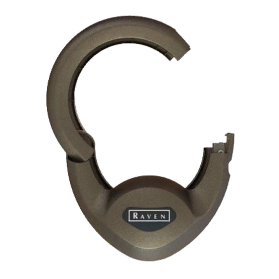
- Page 23 Mechanical Drive Installation Mechanical Drive Installed FIGURE 21. Install the mechanical drive around the installed ring gear assembly, closing it firmly until the latch on the casing is securely locked. Tighten all nuts to ensure the anti-rotation bracket assembly is installed securely. P/N 016-5030-051 Rev.
- Page 24 Chapter 3 Case IH AFX/X230 Combines, Windrower WD/WDX & New Holland CR/CX Combines, Windrower H/HW Series SmarTrax™ MD Installation Man-...
-
Page 25: Node And Wiring Installation
N ode and Wiring CHAPTER C h a p t e r 4 Installation Install the SmarTrax MD Node Node Mounting Locations Node Mounting FIGURE 1. Direction Arrows Any two arrows must be parallel with level ground Mounting Tabs When choosing the location for the SmarTrax node, consider the following points: •... -
Page 26: Mount The Smartrax Md Node - Case Ih Afx, X320 And New Holland Cr, Cs Combines Only
Chapter 4 Mount the SmarTrax MD Node - Case IH AFX, X320 and New Holland CR, CS Combines Only SmarTrax MD Node Installed on Mounting Bracket FIGURE 2. Install the SmarTrax MD node (P/N 063-4001-013) on the node mounting bracket (P/N 107-0172-084) using three 3/8”-16 lock nuts (P/N 312-1001-167). - Page 27 Node and Wiring Installation Node Cover Bracket Removed FIGURE 4. Remove the existing node cover bracket. SmarTrax MD Node Installed FIGURE 5. Align the holes in the node mounting bracket with the machine’s standoffs, orienting the bracket so that the node’s connectors point to the right side of the machine.
-
Page 28: Mount The Smartrax Md Node - Case Ih Windrower Wd/Wdx And New Holland H/Hw Windrower Only
Chapter 4 Mount the SmarTrax MD Node - Case IH Windrower WD/WDX and New Holland H/HW Windrower Only SmarTrax MD Node Installed FIGURE 6. Install the SmarTrax MD node (P/N 063-4001-013) on the node mounting bracket (P/N 107-0172-084) using three 3/8”-16 zinc flanged lock nuts (P/N 312-1001-167). Secure the node mounting bracket to the floor to the right of the operator’s seat using four #10-24 x 3/4”... -
Page 29: Install The Node Harness
Node and Wiring Installation Route the foot switch cable to the node mounting location. Install the Node Harness Node Harness Installed on SmarTrax Node FIGURE 8. Install the two large, rectangular connectors of the node harness (P/N 115-4001-157) into the correct ports of the node (P/N 063-4001-013), tightening the bolts on the connectors to secure the connections. -
Page 30: Install The Chassis Cable - Smartrax Md-Only Systems (If Applicable)
The SmarTrax interface tee is sold separately. Contact your local Raven dealer for ordering information. Locate and disconnect the connection between the Raven console cable and chassis cable on the machine’s existing CAN system. Install the SmarTrax interface tee cable (P/N 115-4001-070 or 115-4001-071) between the chassis and Raven console harness. -
Page 31: Calibrate The Smartrax Md System
Node and Wiring Installation Calibrate the SmarTrax MD System Refer to the SmarTrax MD Calibration & Operation Manual (P/N 016-5030-020) for instructions on calibrating the SmarTrax MD system, adjusting system settings, and system operation. P/N 016-5030-051 Rev. B... - Page 32 Chapter 4 Case IH AFX/X230 Combines, Windrower WD/WDX & New Holland CR/CX Combines, Windrower H/HW Series SmarTrax™ MD Installation Man-...
- Page 33 Index Important Safety Information Electrical Safety 2 Introduction Kit Contents 5 Preparing for Installation 4 Point of Reference 4 Recommendations 4 Updates 4 Kit Contents Mechanical Drive Installation Disassembling the Mechanical Drive Spline Assembly 9 Installing the Anti-Rotation Brackets 12, 17 Installing the Mechanical Drive 17 Installing the Spline and Ring Gear Assemblies 14 Reinstalling the Steering Wheel 16...
- Page 34 Index Case IH AFX/X230 Combines, Windrower WD/WDX & New Holland CR/CX Combines, Windrower H/HW Series SmarTrax™ MD Installation Man-...
Need help?
Do you have a question about the SmarTrax MD Series and is the answer not in the manual?
Questions and answers