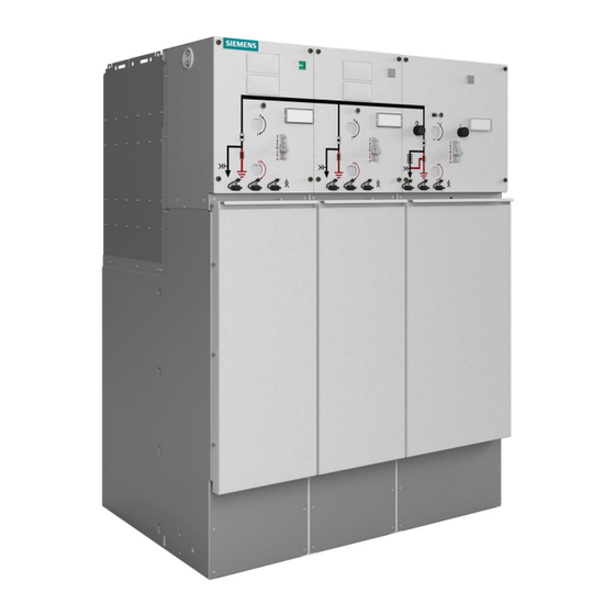
Siemens 8DJH Installation And Operating Instructions Manual
Medium-voltage switchgear
Hide thumbs
Also See for 8DJH:
- Installation and operating instructions manual (174 pages) ,
- Operator's manual (2 pages) ,
- Operator's manual (2 pages)

Related Manuals for Siemens 8DJH


Summary of Contents for Siemens 8DJH
- Page 1 Medium-Voltage Switchgear Medium-Voltage Switchgear Type 8DJH, Block Versions Up to 24 kV, Gas-Insulated Medium-Voltage Switchgear INSTALLATION AND OPERATING INSTRUCTIONS Order No.: 500-8067.9 Revision: 05 Issue: 21-08-2017...
- Page 2 Siemens. Any statements contained herein do not create values and drawings.If not stated otherwise on the new warranties or modify the existing warranty. 2/121 Revision 05 • INSTALLATION AND OPERATING INSTRUCTIONS • 8DJH • 500-8067.9...
-
Page 3: Table Of Contents
16.3 "Spring charged" indicator ........ 85 11.1 Unloading and transport to place of installation ............46 16.4 Ready-for-service indicator ....... 85 11.2 Packing ............48 16.5 Operating tools ..........86 500-8067.9 • INSTALLATION AND OPERATING INSTRUCTIONS • 8DJH • Revision 05 3/121... - Page 4 EARTHED to 23.5 Behavior in case of voltage failure ....117 OPEN position..........96 Siemens Service Hotline .........118 18.5 Protection tripping of the switch-fuse combination ............ 97 Index ...............119 4/121 Revision 05 • INSTALLATION AND OPERATING INSTRUCTIONS • 8DJH • 500-8067.9...
-
Page 5: Safety Instructions
➭ Observe the notes. Symbols used ➭ Operation symbol: Identifies an operation. Asks the operator to perform an operation. ✔ Result symbol: Identifies the result of an operation. 500-8067.9 • INSTALLATION AND OPERATING INSTRUCTIONS • 8DJH • Revision 05 5/121... -
Page 6: General Instructions
➭ After installation and setting, no final check was performed by a service engineer approved by Siemens, including documentation of the test results. ➭ Maintenance was not done according to the operating instructions of the Siemens products. The switchgear corresponds to the relevant laws, prescriptions and standards applicable at the time of delivery. - Page 7 - Actuate the ON pushbutton. - Actuate the OFF pushbutton. ➭ The spring energy store indicator must show "spring not charged". Fig. 1: "Spring not charged" indication Fig. 2: "Spring charged" indication 500-8067.9 • INSTALLATION AND OPERATING INSTRUCTIONS • 8DJH • Revision 05 7/121...
-
Page 8: Security
Safety instructions IT security The Siemens software is regularly checked for safety. If weak points are identified in the process, which may allow third parties to access protection devices, information thereto is distributed through the SIPROTEC and SICAM Security Update Report Newsletter. -
Page 9: Description
860 mm 1170 mm TTRR 1480 mm RLLL 1600 mm 1290 mm RRTT 1480 mm TTTT 1720 mm 1290 mm RLLR 1480 mm LLLL 1720 mm LLRR 1480 mm 500-8067.9 • INSTALLATION AND OPERATING INSTRUCTIONS • 8DJH • Revision 05 9/121... - Page 10 Earthing busbar ④ Pressure relief device ⑪ Partition ⑤ ⑫ Wiring duct (removable) HV HRC fuse assembly ⑥ Switchgear vessel ⑬ Vacuum circuit-breaker ⑦ Operating mechanism of switching device 10/121 Revision 05 • INSTALLATION AND OPERATING INSTRUCTIONS • 8DJH • 500-8067.9...
-
Page 11: Components
⑩ Actuating opening for CLOSING/ OPENING ⑪ Retainer for short-circuit indicator / earth-fault indicator and voltage detecting system Fig. 6: Front operating mechanism box of ring-main panel 500-8067.9 • INSTALLATION AND OPERATING INSTRUCTIONS • 8DJH • Revision 05 11/121... - Page 12 Actuating opening for "spring charging" (switch-disconnector) ⑮ "Spring charged" indicator (switch-disconnector) Fig. 7: Front operating mechanism box of transformer ⑯ Retainer for short-circuit indicator / earth-fault indicator and voltage panel detecting system 12/121 Revision 05 • INSTALLATION AND OPERATING INSTRUCTIONS • 8DJH • 500-8067.9...
-
Page 13: Vacuum Circuit-Breaker Type 2
ON pushbutton for circuit-breaker (mechanical operation) ⑮ Auxiliary switch at the three-position disconnector (option) Fig. 8: Front operating mechanism box of circuit-breaker panel ⑯ type 2 Auxiliary switch at the circuit-breaker (option) 500-8067.9 • INSTALLATION AND OPERATING INSTRUCTIONS • 8DJH • Revision 05 13/121... -
Page 14: Interlocks
Interlocking between circuit-breaker and – – – three-position disconnector X Available O Option – Not available Electrical interlocking On the customer's request, different electrical interlocks can be installed. 14/121 Revision 05 • INSTALLATION AND OPERATING INSTRUCTIONS • 8DJH • 500-8067.9... -
Page 15: Hv Hrc Fuse Assembly
The thermal protection works independently of the type and design of the HV HRC fuse-link used. The thermal protection is maintenance-free and independent of any outside climatic effects. 500-8067.9 • INSTALLATION AND OPERATING INSTRUCTIONS • 8DJH • Revision 05 15/121... -
Page 16: Cable Connection
2 cables per phase 2 cables per phase with surge limiter or surge arrester Thermoplastic-insulated three-core cable 1 cable on request Mass-impregnated cable 1 cable on request Standard Option 16/121 Revision 05 • INSTALLATION AND OPERATING INSTRUCTIONS • 8DJH • 500-8067.9... - Page 17 Cable feeder backwards with elbow Fig. 13: Cable feeder to the front with elbow plugs (interface type A) plugs or T-plugs (interface type C) ① Cable plug ② Earthing 500-8067.9 • INSTALLATION AND OPERATING INSTRUCTIONS • 8DJH • Revision 05 17/121...
- Page 18 N(A)EKBA, N(A)KLEY T = Cable T-plug, W= Cable elbow plug Use of current transformers and current sensors in combination with insulated systems on request Discontinued by the manufacturer 18/121 Revision 05 • INSTALLATION AND OPERATING INSTRUCTIONS • 8DJH • 500-8067.9...
- Page 19 TE Connectivity RSSS 52xx 16...70 Screened; with capacitive measuring point RSES 52xx-R 16...120 Screened; with capacitive measuring point G = Straight cable plug, W = Cable elbow plug 500-8067.9 • INSTALLATION AND OPERATING INSTRUCTIONS • 8DJH • Revision 05 19/121...
- Page 20 K + K Only for 310 mm and 430 mm wide panels. Use of current transformers and current sensors in combination with insulated systems on request On request 20/121 Revision 05 • INSTALLATION AND OPERATING INSTRUCTIONS • 8DJH • 500-8067.9...
-
Page 21: Current And Voltage Transformers
For drawing, see page 20, "Deep cable compartment cover (option)". Current and voltage transformers Technical data The technical data of the current transformers and the voltage transformers is given in the associated order documents. 500-8067.9 • INSTALLATION AND OPERATING INSTRUCTIONS • 8DJH • Revision 05 21/121... -
Page 22: Possibilities For Pressure Relief
The protection equipment and control equipment is designed customer-specifically. The devices are installed in the low-voltage compartment or in the low-voltage niche. Details are given in the respective circuit documentation. 22/121 Revision 05 • INSTALLATION AND OPERATING INSTRUCTIONS • 8DJH • 500-8067.9... -
Page 23: Voltage Detecting Systems
• Independent of temperature and external pressure variations • Independent of the site altitude • Only responds to changes in gas density • Option: Signaling switch 1°changeover contact for remote electrical indication 500-8067.9 • INSTALLATION AND OPERATING INSTRUCTIONS • 8DJH • Revision 05 23/121... -
Page 24: Short-Circuit/Earth-Fault Indicator
The panels can optionally be equipped with short-circuit or earth-fault indicators in different designs. Operating instructions and information on equipment features are available in the respective manufacturing documentation. 24/121 Revision 05 • INSTALLATION AND OPERATING INSTRUCTIONS • 8DJH • 500-8067.9... -
Page 25: Accessories
When switchgear assemblies are delivered with low-voltage compartments, the changed transport data transport dimensions and transport weights as well as the relocation of the center of gravity must be observed. 500-8067.9 • INSTALLATION AND OPERATING INSTRUCTIONS • 8DJH • Revision 05 25/121... -
Page 26: Technical Data
The rated normal currents apply to ambient air temperatures of max. 40 °C. The 24-hour mean value is max. 35 °C (according to IEC/EN 62271-1/VDE 0671-1). Depending on the HV HRC fuse-link Depending on the secondary equipment used 26/121 Revision 05 • INSTALLATION AND OPERATING INSTRUCTIONS • 8DJH • 500-8067.9... -
Page 27: Three-Position Switch-Disconnector
Switching capacity for make-proof earthing switches (with HV HRC fuses-links on feeder side) Rated voltage U 17.5 Rated short-circuit making current I 50 Hz 60 Hz Rated short-time withstand current with t = 1 s kA 500-8067.9 • INSTALLATION AND OPERATING INSTRUCTIONS • 8DJH • Revision 05 27/121... -
Page 28: Three-Position Disconnector
Rated short-circuit making current I 50 Hz up to kA 50/52.5 60 Hz up to kA 52/55 Number of short-circuit making operations / Classification 5 / E2 Design option 28/121 Revision 05 • INSTALLATION AND OPERATING INSTRUCTIONS • 8DJH • 500-8067.9... -
Page 29: Vacuum Circuit-Breaker
2nd shunt release (-Y3) < 65 release C.t.-operated release (-Y6) < 65 Undervoltage release (-Y7) < 65 Low-energy release (-Y6) < 65 Minimum command duration CLOSED Closing solenoid (-Y9) 500-8067.9 • INSTALLATION AND OPERATING INSTRUCTIONS • 8DJH • Revision 05 29/121... - Page 30 The closing solenoid closes the circuit-breaker electrically. The closing command is executed by application of an auxiliary voltage (AC or DC, depending on the design option). After closing, the closing solenoid is de-energized internally. 30/121 Revision 05 • INSTALLATION AND OPERATING INSTRUCTIONS • 8DJH • 500-8067.9...
- Page 31 The low-energy release (-Y6) is provided for use in combination with the transformer monitor IKI-30 (make Kries) or the protection device 7SJ45 (make Siemens) supplied with instrument transformer current. The tripping circuit is supplied through the current sensor or current transformer.
-
Page 32: Classification Of The Switchgear
Description Classification of the switchgear 8DJH switchgear is classified according to IEC/EN 62 271-200 / VDE 0671-200. Partition class Partition class PM (metallic partition) Loss of service continuity category Switchgear panel Loss of service continuity category with LSC 2 Three-position disconnector or three-position switch-disconnector... - Page 33 EMC Directive. Degrees of protection The panels of the 8DJH fulfill the following degrees of protection according to IEC 62271-200, IEC 60529 and DIN VDE 0671-200: • IP2X (standard) for parts under high voltage in switchgear panels with HV HRC fuses •...
-
Page 34: Dimensions And Weights
Applies to design with circuit-breaker type 2 Packing weights Maximum width of Packing weight for Europe, Packing weight for overseas, switchgear unit [mm] approx. [kg] approx. [kg] 1200 1550 1800 2000 34/121 Revision 05 • INSTALLATION AND OPERATING INSTRUCTIONS • 8DJH • 500-8067.9... -
Page 35: Phase Sequence
HV HRC fuses. For these site altitudes, a higher insulation level must be selected, which results from the multiplication of the rated insulation level for 0 to 1000 m with the altitude correction factor K 500-8067.9 • INSTALLATION AND OPERATING INSTRUCTIONS • 8DJH • Revision 05 35/121... - Page 36 According to the above "Dielectric strength" table, switchgear for a rated voltage of 24 kV with a rated lightning impulse withstand voltage of 125 kV is to be selected. 36/121 Revision 05 • INSTALLATION AND OPERATING INSTRUCTIONS • 8DJH • 500-8067.9...
-
Page 37: Selection Of Hv Hrc Fuse-Links
ATTENTION Please use only fuses tested by Siemens, which are listed in the following fuse tables. ➭ The use of other fuse types must be checked by Siemens in advance. Please contact the regional Siemens representative. 500-8067.9 • INSTALLATION AND OPERATING INSTRUCTIONS • 8DJH • Revision 05... - Page 38 30 098 13.10 – 3…7.2 30 098 13.16 – 3…7.2 30 098 13.16 – 3…7.2 30 098 13.20 – 11.5 3…7.2 30 098 13.16 – 3…7.2 30 098 13.20 – 38/121 Revision 05 • INSTALLATION AND OPERATING INSTRUCTIONS • 8DJH • 500-8067.9...
- Page 39 30 012 43.63 45DB120V63PTS2 30.3 3…7.2 30 098 13.50 – 6…12 30 004 13.50 45DB120V50PTD 6…12 30 101 13.50 – 6…12 30 012 43.63 45DB120V63PTS2 6…12 – 45DB120V80PTS2 500-8067.9 • INSTALLATION AND OPERATING INSTRUCTIONS • 8DJH • Revision 05 39/121...
- Page 40 10…17.5 30 231 13.25 – 10…24 30 006 13.25 45DB240V25PTD 31.5 6…12 30 004 13.31,5 – 31.5 6…12 30 101 13.31,5 – 31.5 10…17.5 30 221 13.31,5 – 40/121 Revision 05 • INSTALLATION AND OPERATING INSTRUCTIONS • 8DJH • 500-8067.9...
- Page 41 30 006 13.10 45DB240V10PTD 10…17.5 30 231 13.10 – 10…17.5 30 231 13.16 – 10…24 30 006 13.16 45DB240V16PTD 10…17.5 30 231 13.10 – 10…17.5 30 231 13.16 – 500-8067.9 • INSTALLATION AND OPERATING INSTRUCTIONS • 8DJH • Revision 05 41/121...
- Page 42 – 10…24 30 006 13.40 – 10…17.5 30 232 13.50 – 10…24 30 014 13.50 45DB240V50PTD 10…24 30 014 43.63 – 5…6 30.9 10…24 30 014 43.63 – 42/121 Revision 05 • INSTALLATION AND OPERATING INSTRUCTIONS • 8DJH • 500-8067.9...
- Page 43 Rated power of transformer Relative impedance voltage of transformer Rated current of transformer Rated current of fuse Operating voltage / rated voltage of fuse Reference dimension of the fuse 500-8067.9 • INSTALLATION AND OPERATING INSTRUCTIONS • 8DJH • Revision 05 43/121...
-
Page 44: Rating Plates
Rating plate inside the operating mechanism box (example) ① Switchgear type and year of manufacture ④ Technical data ② ⑤ Serial number Number of operating instructions ③ Internal arc classification (option) 44/121 Revision 05 • INSTALLATION AND OPERATING INSTRUCTIONS • 8DJH • 500-8067.9... -
Page 45: Switchgear Maintenance
Auxiliary devices such as short-circuit indicators have to be recycled as electronic scrap. Any existing batteries have to be recycled professionally. As delivered by Siemens, the switchgear does not contain hazardous materials as per the Hazardous Material Regulations applicable in the Federal Republic of Germany. For operation in other countries, the locally applicable laws and regulations must be observed. -
Page 46: Installation
➭ Observe the installation order of the panels during transport to the switchgear room; leave space for moving and mounting. ➭ Remove the packing close to the place of installation of the panels, and not before beginning the installation process. 46/121 Revision 05 • INSTALLATION AND OPERATING INSTRUCTIONS • 8DJH • 500-8067.9... - Page 47 , and turn the transport eyes upwards by 180°. ② ➭ Re-tighten the bolt-and-washer assembly ① Lifting eye ② Bolt-and-washer assembly ➭ Attach the lifting equipment or the rod. ➭ Transport the switchgear. 500-8067.9 • INSTALLATION AND OPERATING INSTRUCTIONS • 8DJH • Revision 05 47/121...
-
Page 48: Packing
Transport units consist either of individual panels or panel blocks with max. four functions, and the switchgear accessories. The switchgear accessories are packed in the cable compartment of the first panel or in a separate transport box, depending on the extent. 48/121 Revision 05 • INSTALLATION AND OPERATING INSTRUCTIONS • 8DJH • 500-8067.9... -
Page 49: Completeness And Transport Damage
➭ Determine and document detected defects and transport damages immediately, e.g. on the freight documents. ➭ Document larger defects and transport damages photographically. ➭ Please contact the regional Siemens representative in order to repair the transport damages. 11.4 Intermediate storage... - Page 50 • Protected against vermin (e.g. rats, mice, insects), and vegetation overgrowth Instructions for intermediate storage: • Do not unpack small parts (to prevent corrosion and loss) • Check packing for ingress of humidity (condensation) every 4 weeks 50/121 Revision 05 • INSTALLATION AND OPERATING INSTRUCTIONS • 8DJH • 500-8067.9...
-
Page 51: Switchgear Installation
Suction of drilling chips, construction waste, dust Vacuum cleaner 12.3 Mounting paste Use mounting paste only according to the installation instructions. Use only the supplied or released mounting paste. 500-8067.9 • INSTALLATION AND OPERATING INSTRUCTIONS • 8DJH • Revision 05 51/121... -
Page 52: Tightening Torques
Installation 12.4 Tightening torques If not stated otherwise, the following tightening torques apply to 8DJH switchgear: Joint Material/material Thread Tightening torque Metal joints sheet-steel/sheet-steel M6 (self-tapping) 12 Nm e. g.: front plates, top 30 Nm plates, etc. Earthing busbar sheet-steel/copper... - Page 53 If shields are used as protective earth conductors at the same time, the connected plastic- insulated lead must be marked green/yellow over its entire length. Non-insulated connections are inadmissible. 500-8067.9 • INSTALLATION AND OPERATING INSTRUCTIONS • 8DJH • Revision 05 53/121...
-
Page 54: Preparing The Switchgear Room
The door dimensions depend on the - Number of panels in a transport unit - Design with or without low-voltage compartment Weights For data, see page 34, "Dimensions and weights". 54/121 Revision 05 • INSTALLATION AND OPERATING INSTRUCTIONS • 8DJH • 500-8067.9... -
Page 55: Preparing The Foundation
➭ Lower the transport units by means of the lateral transport angles onto roller pads (reinforced rollers) or tubes. ➭ Lift the switchgear at the side edges with roller crowbars and slowly lower it onto the mounting position. ➭ Remove transport angles. 500-8067.9 • INSTALLATION AND OPERATING INSTRUCTIONS • 8DJH • Revision 05 55/121... - Page 56 Transport angle for wooden pallet ➭ Screw the fixing bolts in again on both sides of the transport unit. Fig. 28: Points for fixing bolts (view from the left) 56/121 Revision 05 • INSTALLATION AND OPERATING INSTRUCTIONS • 8DJH • 500-8067.9...
-
Page 57: Checking Service Readiness
If the cross member was removed, the bracing required for the stability of the panel during movement is missing. ➭ If the cross member is removed, do not move the panel. 500-8067.9 • INSTALLATION AND OPERATING INSTRUCTIONS • 8DJH • Revision 05 57/121... - Page 58 (example) foundation ① Conical spring washer M8 (DIN 6796) ④ Panel frame ② ⑤ 3D washer M10 (DIN EN ISO 7093) Foundation or foundation rail ③ Bolt M8 58/121 Revision 05 • INSTALLATION AND OPERATING INSTRUCTIONS • 8DJH • 500-8067.9...
-
Page 59: 12.11 Floor Openings And Fixing Points
Siemens representative. Dimension drawing Panel block Width 620 mm 1050 mm 740 mm 1050 mm 930 mm RRRR 1240 mm 500-8067.9 • INSTALLATION AND OPERATING INSTRUCTIONS • 8DJH • Revision 05 59/121... - Page 60 TTTT 1720 mm LLLL Versions with deep cable compartment covers (e.g. for double cable connections) Dimension drawings for other versions can be ordered via the regional Siemens representative. Panel width 310/430 mm Deep cable compartment cover Deep cable compartment cover with base extension...
- Page 61 Type RRT deeper by 105 mm Type RRT deeper by 250 mm Versions combined with pressure absorbers and deep cable compartment covers Dimension drawings for other versions can be ordered via the regional Siemens representative. Panel width 310/430 mm • Ring-main panel type R •...
-
Page 62: 12.12 Earthing The Switchgear
Earthing point (view from outside) Fig. 35: Earthing point (view into cable compartment) ① Earthing point (earthing bolt M12) ➭ Connect the earthing point ① with the substation earth. 62/121 Revision 05 • INSTALLATION AND OPERATING INSTRUCTIONS • 8DJH • 500-8067.9... -
Page 63: Electrical Connections
For perfect installation of the cable plugs, the following must be observed: ➭ Mount the cable plugs according to the manufacturer's stipulations. ➭ If there are no stipulations by the cable plug manufacturer, please contact the regional Siemens representative. 500-8067.9 • INSTALLATION AND OPERATING INSTRUCTIONS • 8DJH • Revision 05 63/121... - Page 64 ➭ Fit the cable plugs on the conductor ends according to the manufacturer’s instructions. ➭ Optionally: Mount ring-core current sensors (see page 71, "Installing ring-core current sensors at the cable connection"). 64/121 Revision 05 • INSTALLATION AND OPERATING INSTRUCTIONS • 8DJH • 500-8067.9...
- Page 65 • Depending on their type, double cable connections require a deep cable compartment cover and larger floor openings. • Depending on their type, surge arresters also require a deep cable compartment cover. For further information, see page 16, "Cable connection". 500-8067.9 • INSTALLATION AND OPERATING INSTRUCTIONS • 8DJH • Revision 05 65/121...
-
Page 66: Installing Cable Plugs Type Raychem Rics5Xxx With Rda
Mounting the surge arrester plate and the adapter feet ➭ Fasten the upper cross member with 4 self-tapping bolts M6 ① . Fig. 38: Mounting the upper cross member 66/121 Revision 05 • INSTALLATION AND OPERATING INSTRUCTIONS • 8DJH • 500-8067.9... - Page 67 The use of RICS5xxx cable plugs with RDA in panels with a width of 310 mm is allowed under normal ambient conditions despite the reduced distance (according to IEC 62271-1). ✔ The installation of the Raychem RICS5xxx cable plug with RDA is completed. 500-8067.9 • INSTALLATION AND OPERATING INSTRUCTIONS • 8DJH • Revision 05 67/121...
-
Page 68: Cable Connection With Cable-Type Current Transformers
➭ Swing the high-voltage cables in together with the cable-type current transformers, and connect the cable plugs to the cable feeder (see page 63, "Connecting high-voltage cables"). ➭ Install the current transformers. 68/121 Revision 05 • INSTALLATION AND OPERATING INSTRUCTIONS • 8DJH • 500-8067.9... - Page 69 Self-tapping Torx bolt M6x16 ⑤ Transformer mounting plate ⑥ Current transformer ⑦ Cable clamp ⑧ Cable bracket ⑨ Nut-and-washer assembly M8 Fig. 42: Principle of installation for 4MC7032 and 4MC7033 500-8067.9 • INSTALLATION AND OPERATING INSTRUCTIONS • 8DJH • Revision 05 69/121...
- Page 70 ➭ Mount the cross member (see page 77, "Removing and mounting the cross member"). installation of the cable- ➭ Hook the cable compartment cover in (see page 76, "Removing and mounting the cable type current transformers compartment cover"). 70/121 Revision 05 • INSTALLATION AND OPERATING INSTRUCTIONS • 8DJH • 500-8067.9...
-
Page 71: Installing Ring-Core Current Sensors At The Cable Connection
➭ Connect the cable plugs together with the ring-core current sensors at the bushings, see page 63, "Connecting high-voltage cables". 500-8067.9 • INSTALLATION AND OPERATING INSTRUCTIONS • 8DJH • Revision 05 71/121... -
Page 72: Installing Voltage Sensors
Tightening torque: 30 Nm max. ② Connection of earthing cable Conductor cross-section: min. 6 mm Tightening torque: 6 Nm max. ③ Plug connection of the measuring lead Fig. 47: Voltage sensor (example) 72/121 Revision 05 • INSTALLATION AND OPERATING INSTRUCTIONS • 8DJH • 500-8067.9... - Page 73 Connect according to the circuit diagram. For wire routing, see page 71, "Installing ring-core current sensors at the cable connection". 500-8067.9 • INSTALLATION AND OPERATING INSTRUCTIONS • 8DJH • Revision 05 73/121...
-
Page 74: Connecting The Secondary Equipment
⑤ Fixing duct ② ⑥ Lateral wiring ducts (recommended wire routing downwards) Terminal strip ③ Wire routing through the operating mechanism box ⑦ Customer-side wiring ④ Ready-for-service indicator 74/121 Revision 05 • INSTALLATION AND OPERATING INSTRUCTIONS • 8DJH • 500-8067.9... -
Page 75: Correcting Circuit Diagrams
13.7 Correcting circuit diagrams ➭ Document any modification due to installation. ➭ Document the modifications in the circuit diagram. ➭ Send documented modifications to the regional Siemens representative. 500-8067.9 • INSTALLATION AND OPERATING INSTRUCTIONS • 8DJH • Revision 05 75/121... -
Page 76: Recurring Activities
➭ Hook the cable compartment cover in from above. compartment cover ➭ On cable panels, bolt the cable compartment cover to the panel using the 2 self-tapping bolts ② removed before. 76/121 Revision 05 • INSTALLATION AND OPERATING INSTRUCTIONS • 8DJH • 500-8067.9... -
Page 77: Removing And Mounting The Cross Member
6 bolts ② . ➭ Fasten the cross member to the foundation again using the floor fixing bolt ③ . ✔ The installation of the cross member is completed. 500-8067.9 • INSTALLATION AND OPERATING INSTRUCTIONS • 8DJH • Revision 05 77/121... -
Page 78: Commissioning
- Circuit diagrams - Warning signs - Indicators for the capacitive voltage detecting system with HR plug-in sockets or LRM plug-in sockets (optional) - Keys for low-voltage compartment (optional) 78/121 Revision 05 • INSTALLATION AND OPERATING INSTRUCTIONS • 8DJH • 500-8067.9... -
Page 79: Mechanical And Electrical Function Test
➭ The spring energy store indicator must show "spring not charged". ➭ Remove the front plate. ➭ Insert the retaining bolt of the striker at the undervoltage release in the desired position. ✔ Mount the front plate. 500-8067.9 • INSTALLATION AND OPERATING INSTRUCTIONS • 8DJH • Revision 05 79/121... -
Page 80: Preparing The Power-Frequency Voltage Test
➭ Earth the capacitive test sockets. ✔ The power-frequency voltage test can now be performed. 15.4 Instructing the operating personnel ➭ Instruct operating personnel in theory and practice of switchgear operation. 80/121 Revision 05 • INSTALLATION AND OPERATING INSTRUCTIONS • 8DJH • 500-8067.9... -
Page 81: Applying Operating Voltage
When all incoming feeders are connected to the busbar: feeders ➭ One after the other, energize all consumer feeders with connected consumers. ✔ When all consumer feeders are energized, the switchgear is completely in operation. 500-8067.9 • INSTALLATION AND OPERATING INSTRUCTIONS • 8DJH • Revision 05 81/121... - Page 82 - Electricians and persons who have been properly instructed in electrical engineering - Persons under the supervision of electricians and persons who have been properly instructed in electrical engineering 82/121 Revision 05 • INSTALLATION AND OPERATING INSTRUCTIONS • 8DJH • 500-8067.9...
-
Page 83: Operation
ATTENTION Earthing a live incoming cable will result in a short circuit and trip an upstream circuit-breaker. ➭ Verify safe isolation from supply of the feeder before earthing. 500-8067.9 • INSTALLATION AND OPERATING INSTRUCTIONS • 8DJH • Revision 05 83/121... -
Page 84: Indicators And Control Elements
ON pushbutton for circuit-breaker ③ Control gate/locking device for circuit-breaker ④ Position indicator for circuit-breaker ⑤ Operations counter ⑥ OFF pushbutton for circuit-breaker Fig. 56: 8DJH circuit-breaker panel type L2 84/121 Revision 05 • INSTALLATION AND OPERATING INSTRUCTIONS • 8DJH • 500-8067.9... -
Page 85: Position Indicators
Siemens Service Hotline. ① Indication "ready for service" ② Pointer ③ Green ④ ⑤ Indication "not ready for service"/ "do not operate" Fig. 57: Ready-for-service indicator 500-8067.9 • INSTALLATION AND OPERATING INSTRUCTIONS • 8DJH • Revision 05 85/121... -
Page 86: Operating Tools
Every operating lever can be retrofitted to an anti-reflex lever: Remove the setscrew ① from the standard operating lever. ① Setscrew Fig. 58: Standard operating lever, Fig. 59: Retrofitting to an anti- short reflex lever 86/121 Revision 05 • INSTALLATION AND OPERATING INSTRUCTIONS • 8DJH • 500-8067.9... -
Page 87: Mechanical Interlocking With Padlock
The local-remote switch latches tight in the selected setting. Local setting: Local operation by motor Remote setting: Remote operation by motor from the control room or monitoring station 500-8067.9 • INSTALLATION AND OPERATING INSTRUCTIONS • 8DJH • Revision 05 87/121... -
Page 88: Momentary-Contact Rotary Control Switch For Motor Operating Mechanism (Option)
➭ Push the control gate upwards. ➭ Turn the key in the cylinder lock according to the interlocking condition, and remove it. ✔ Push the control gate downwards. 88/121 Revision 05 • INSTALLATION AND OPERATING INSTRUCTIONS • 8DJH • 500-8067.9... -
Page 89: Operating The Panel With Switch-Disconnector
➭ Remove the padlock (optional) from the locking device. Releasing the actuating ➭ Push the control gate (optional) upwards, and hold it. opening ✔ The actuating opening of the switch-disconnector is open. 500-8067.9 • INSTALLATION AND OPERATING INSTRUCTIONS • 8DJH • Revision 05 89/121... -
Page 90: Switching The Three-Position Switch-Disconnector From Closed To Open Position
➭ Remove the operating lever. The control gate returns to its initial position. ➭ Fit the padlock (optional) on the locking device in the desired position (see page 87, "Mechanical interlocking with padlock"). 90/121 Revision 05 • INSTALLATION AND OPERATING INSTRUCTIONS • 8DJH • 500-8067.9... -
Page 91: Switching The Three-Position Switch-Disconnector From Open To Earthed Position
➭ Remove the operating lever. The control gate returns to its initial position. ➭ Fit the padlock (optional) on the locking device in the desired position (see page 87, "Mechanical interlocking with padlock"). 500-8067.9 • INSTALLATION AND OPERATING INSTRUCTIONS • 8DJH • Revision 05 91/121... -
Page 92: Switching The Three-Position Switch-Disconnector From Earthed To Open Position
➭ Remove the operating lever. The control gate returns to its initial position. ➭ Fit the padlock (optional) on the locking device in the desired position (see page 87, "Mechanical interlocking with padlock"). 92/121 Revision 05 • INSTALLATION AND OPERATING INSTRUCTIONS • 8DJH • 500-8067.9... -
Page 93: Operating The Panel With Switch-Fuse Combination
Actuating opening for earthing switch ⑥ Position indicator for earthing switch ⑦ Position indicator for switch-disconnector ⑧ OFF pushbutton ⑨ Actuating opening for "spring charging" ⑩ "Spring charged" indicator 500-8067.9 • INSTALLATION AND OPERATING INSTRUCTIONS • 8DJH • Revision 05 93/121... -
Page 94: Switching The Three-Position Switch-Disconnector From Open To Closed Position
The switch-disconnector can be damaged by no-load switching. After charging the spring energy store, do not open the switch-disconnector directly. ➭ After charging the spring energy store, close the switch-disconnector first, and then open 94/121 Revision 05 • INSTALLATION AND OPERATING INSTRUCTIONS • 8DJH • 500-8067.9... -
Page 95: Switching The Three-Position Switch-Disconnector From Closed To Open Position
➭ Remove the padlock (optional) from the locking device. Releasing the actuating ➭ Push the control gate downwards, and hold it. opening ✔ The actuating opening of the earthing switch is open. 500-8067.9 • INSTALLATION AND OPERATING INSTRUCTIONS • 8DJH • Revision 05 95/121... -
Page 96: Switching The Three-Position Switch-Disconnector From Earthed To Open Position
➭ Insert the operating lever and turn straight counter- position clockwise as far as it will go. ✔ The position indicator of the earthing switch shows the OPEN position. ✔ The feeder is de-earthed. 96/121 Revision 05 • INSTALLATION AND OPERATING INSTRUCTIONS • 8DJH • 500-8067.9... -
Page 97: Protection Tripping Of The Switch-Fuse Combination
➭ Switch the switching device to EARTHED position. readiness ➭ Replace all HV HRC fuse-links (see page 109, "Replacing HV HRC fuse-links"). The fuse-links may also be damaged if their striker was not tripped. 500-8067.9 • INSTALLATION AND OPERATING INSTRUCTIONS • 8DJH • Revision 05 97/121... -
Page 98: Operating The Panel With Circuit-Breaker Type 2
⑤ Control gate/locking device for three-position ⑫ Operations counter disconnector ⑥ Padlock (option) ⑬ OFF pushbutton for circuit-breaker ⑦ ⑭ Actuating opening for earthing switch "Spring charged" indicator 98/121 Revision 05 • INSTALLATION AND OPERATING INSTRUCTIONS • 8DJH • 500-8067.9... -
Page 99: Charging The Spring Energy Store In Circuit-Breaker Type 2 Manually
✔ The control gate of the circuit-breaker returns to its initial position. ✔ The spring energy store is charged. The circuit-breaker can now be closed and opened again. 500-8067.9 • INSTALLATION AND OPERATING INSTRUCTIONS • 8DJH • Revision 05 99/121... -
Page 100: Closing Circuit-Breaker Type 2
Opening the circuit- ➭ Actuate the OFF pushbutton. breaker ✔ The position indicator of the circuit-breaker shows the OPEN position. ✔ "Spring charged" indicator shows "spring not charged". 100/121 Revision 05 • INSTALLATION AND OPERATING INSTRUCTIONS • 8DJH • 500-8067.9... -
Page 101: Switching The Three-Position Disconnector From Open To Closed Position
Releasing the actuating ➭ Push the control gate of the three-position opening disconnector upwards, and hold it. ✔ The actuating opening of the disconnector is open. 500-8067.9 • INSTALLATION AND OPERATING INSTRUCTIONS • 8DJH • Revision 05 101/121... -
Page 102: Switching The Three-Position Disconnector From Open To Earthed Position
✔ The control gate returns to its initial position. ➭ Fit the padlock (optional) on the locking device in the desired position (see page 87, "Mechanical interlocking with padlock"). 102/121 Revision 05 • INSTALLATION AND OPERATING INSTRUCTIONS • 8DJH • 500-8067.9... -
Page 103: Switching The Three-Position Disconnector From Earthed To Open Position
✔ The control gate returns to its initial position. ➭ Fit the padlock (optional) on the locking device in the desired position (see page 87, "Mechanical interlocking with padlock"). 500-8067.9 • INSTALLATION AND OPERATING INSTRUCTIONS • 8DJH • Revision 05 103/121... -
Page 104: Verification Of Safe Isolation From Supply
✔ If the HR or LRM voltage indicator does not flash or light up in any of the 3 phases, the phases are not live. ➭ Refit the covers on the plug-in sockets. 104/121 Revision 05 • INSTALLATION AND OPERATING INSTRUCTIONS • 8DJH • 500-8067.9... - Page 105 The marking for documentation of the repeat test of the interface condition is located next to the HR or LRM plug-in sockets: Fig. 61: Documentation to repeat test of interface condition 500-8067.9 • INSTALLATION AND OPERATING INSTRUCTIONS • 8DJH • Revision 05 105/121...
-
Page 106: Vois And Capdis Indications
Fig. 64: CAPDIS-S2+: Cover opened ① LC display ② Test socket L2 ③ Earth socket ④ Test socket L3 ⑤ Test socket L1 Fig. 65: VOIS+: Cover opened 106/121 Revision 05 • INSTALLATION AND OPERATING INSTRUCTIONS • 8DJH • 500-8067.9... - Page 107 Overvoltage present (lights up permanently). U ≠ 0 U = 0 Indication: "ERROR" e.g. in case of missing auxiliary voltage. LED does not light up, LED lights up 500-8067.9 • INSTALLATION AND OPERATING INSTRUCTIONS • 8DJH • Revision 05 107/121...
-
Page 108: Wega Indications
• Voltage present and integrated repeat test passed. • Voltage signal too high. U ≠ 0 U = 0 • Auxiliary voltage missing. LED does not light up, LED lights up 108/121 Revision 05 • INSTALLATION AND OPERATING INSTRUCTIONS • 8DJH • 500-8067.9... -
Page 109: Replacing Hv Hrc Fuse-Links
ATTENTION HV HRC fuse-links may be hot! ➭ Let HV HRC fuse-links cool down or wear gloves to withdraw the fuse slide. 500-8067.9 • INSTALLATION AND OPERATING INSTRUCTIONS • 8DJH • Revision 05 109/121... - Page 110 Incorrectly selected or mounted fuse-links and extension tubes can damage the fuse box or the switchgear. ➭ 7.2 kV fuse-links with dimension 192 mm and 24 kV fuse-links with dimension 292 mm are not permissible. 110/121 Revision 05 • INSTALLATION AND OPERATING INSTRUCTIONS • 8DJH • 500-8067.9...
- Page 111 ➭ The cable compartment cover can only be hooked in correctly if the fuse slides are properly compartment cover latched in. ➭ Hook the cable compartment cover in, see page 76, "Removing and mounting the cable compartment cover". 500-8067.9 • INSTALLATION AND OPERATING INSTRUCTIONS • 8DJH • Revision 05 111/121...
-
Page 112: Cable Testing
➭ Fit cable test elements (e.g. measuring bolts) according to the operating instructions of the plug manufacturers. ① Bushing ② Measuring bolt ③ Test lead ④ Earthing connection of cable shield ⑤ Earthing connection of plug ⑥ T-plug 112/121 Revision 05 • INSTALLATION AND OPERATING INSTRUCTIONS • 8DJH • 500-8067.9... -
Page 113: Cable Sheath Test
➭ Earth the cable shield again at the cross member of the subframe as well as in the opposite substation. ➭ Refit and lock the cable compartment cover. ➭ De-earth the panel and the opposite substation, and re-energize the feeder. 500-8067.9 • INSTALLATION AND OPERATING INSTRUCTIONS • 8DJH • Revision 05 113/121... -
Page 114: Annex
MCU (Motor Control Unit) 23.1 Extract from the Technical Description The 8DJH can be equipped with different versions of the electrical motor control unit (MCU). The following sections are an extract from the Technical Description of the electrical motor control unit. -
Page 115: Fault Signals
• Through the reset button at the device (operation of the reset button: insert a thin, pointed object through the opening at the front side.) • By removing and re-applying the control voltage 500-8067.9 • INSTALLATION AND OPERATING INSTRUCTIONS • 8DJH • Revision 05 115/121... - Page 116 OPEN position by the motor when a new command is entered. • If the operating mechanism was moved manually from the intermediate position to a defined end position because the load voltage failed. 116/121 Revision 05 • INSTALLATION AND OPERATING INSTRUCTIONS • 8DJH • 500-8067.9...
-
Page 117: Behavior In Case Of Voltage Failure
• The operating mechanism must be moved manually to a defined end position if the control voltage has failed. • Electrical movement to the OPEN position is possible again. • Normal operation is established. 500-8067.9 • INSTALLATION AND OPERATING INSTRUCTIONS • 8DJH • Revision 05 117/121... -
Page 118: Siemens Service Hotline
- +55 11 4585 8040 - suporte.br@siemens.com - Local working hours • Customer Support India (for Indian market only) - +91 1 800 419 7477 - service.energy.in@siemens.com - Local working hours 118/121 Revision 05 • INSTALLATION AND OPERATING INSTRUCTIONS • 8DJH • 500-8067.9... -
Page 119: Index
Mounting paste .............. 51 Electrical connections ............. 63 Operating tools............... 86 Fault mode, clearing ............. 115 Operating voltage, applying..........81 Fault signal, no output..........116 Operation ............... 83 500-8067.9 • INSTALLATION AND OPERATING INSTRUCTIONS • 8DJH • Revision 05 119/121... - Page 120 Short-circuit/earth-fault indicator ........24 Signal terms and definitions..........5 WEGA ................108 Spring charged-indicator..........85 Weights ................34 Spring energy store, manual charging, circuit-breaker type 2 ............99 120/121 Revision 05 • INSTALLATION AND OPERATING INSTRUCTIONS • 8DJH • 500-8067.9...
- Page 121 Imprint Siemens AG Energy Management Medium Voltage & Systems Switchgear Factory Frankfurt Carl-Benz-Str. 22 D-60386 Frankfurt © Siemens AG 2017 500-8067.9 • INSTALLATION AND OPERATING INSTRUCTIONS • 8DJH • Revision 05 121/121...
Need help?
Do you have a question about the 8DJH and is the answer not in the manual?
Questions and answers