Table of Contents
Advertisement
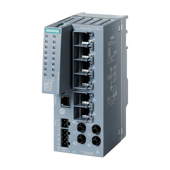
SIMATIC NET
Industrial Ethernet switches
SCALANCE XC-200
Operating Instructions
12/2017
C79000-G8976-C442-03
Introduction
Safety notices
Description of the device
Mounting
Connecting up
Maintenance and
troubleshooting
Technical specifications
Dimension drawings
Certifications and approvals
1
2
3
4
5
6
7
8
9
Advertisement
Table of Contents


Need help?
Do you have a question about the SIMATIC NET SCALANCE XC-200 Series and is the answer not in the manual?
Questions and answers