
Subscribe to Our Youtube Channel
Related Manuals for Siemens RUGGEDCOM RS920L


Summary of Contents for Siemens RUGGEDCOM RS920L
- Page 1 Edition 11/2022 Installation Manual SIMATIC NET Rugged Ethernet Switches RUGGEDCOM RS920L https://www.siemens.com/ruggedcom...
- Page 2 Preface Introduction Installing the Device SIMATIC NET Device Management Rugged Ethernet Switches RUGGEDCOM RS920L Communication Ports Technical Specifications Installation Manual Certification 11/2022 C79000-G8976-1032-11...
- Page 3 Note the following: WARNING Siemens products may only be used for the applications described in the catalog and in the relevant technical documentation. If products and components from other manufacturers are used, these must be recommended or approved by Siemens. Proper transport, storage, installation, assembly, commissioning, operation and maintenance are required to ensure that the products operate safely and without any problems.
-
Page 4: Table Of Contents
Accessing Documentation ....................... v Registered Trademarks ......................v Warranty ..........................vi Training ..........................vi Customer Support ........................vii Contacting Siemens ....................... vii Introduction ........................... 1 Feature Highlights ....................1 Description ......................2 Required Tools and Materials ................. 4 Decommissioning and Disposal ................4 Cabling Recommendations .................. - Page 5 FDA/CDRH ......................33 6.1.5 ISED ........................33 6.1.6 TÜV SÜD ......................33 6.1.7 ISO ........................33 6.1.8 ACMA ........................33 6.1.9 RoHS ........................34 6.1.10 Other Approvals ....................34 EMC and Environmental Type Tests ..............34 RUGGEDCOM RS920L Installation Manual, 11/2022, C79000-G8976-1032-11...
-
Page 6: Preface
Preface This guide describes the RUGGEDCOM RS920L. It describes the major features of the device, installation, commissioning and important technical specifications. It is intended for use by network technical support personnel who are responsible for the installation, commissioning and maintenance of the device. It is also recommended for use by network and system planners, system programmers, and line technicians. -
Page 7: Warranty
Warranty Siemens warrants this product for a period of five (5) years from the date of purchase, conditional upon the return to factory for maintenance during the warranty term. This product contains no user-serviceable parts. Attempted service by unauthorized personnel shall render all warranties null and void. -
Page 8: Customer Support
Call a local hotline center to submit a Support Request (SR). To locate a local hotline center, visit https://w3.siemens.com/aspa_app/?lang=en. Mobile App Install the Industry Online Support app by Siemens AG on any Android, Apple iOS or Windows mobile device and be able to: •... - Page 9 Preface Contacting Siemens viii RUGGEDCOM RS920L Installation Manual, 11/2022, C79000-G8976-1032-11...
-
Page 10: Introduction
85 °C (-40 to 185 °F), optional conformal coating, and a galvanized steel enclosure allows the RUGGEDCOM RS920L to be placed in almost any location. The RUGGEDCOM RS920L can be mounted on a DIN rail or panel for efficient use of cabinet space. -
Page 11: Description
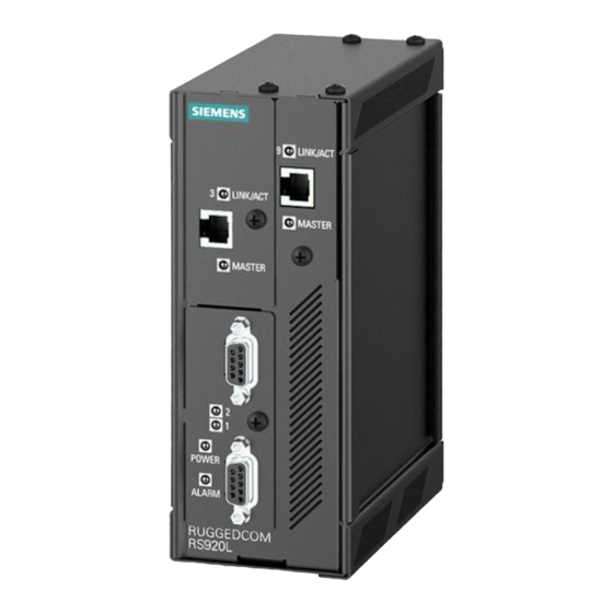
Terminal blocks for reliable maintenance free connections • CSA/UL 62368-1 safety approved to 85 °C (185 °F) Description The RUGGEDCOM RS920L features various ports, controls and indicator LEDs on the front panel for connecting, configuring and troubleshooting the device. RUGGEDCOM RS920L Installation Manual, 11/2022, C79000-G8976-1032-11... - Page 12 RS232 Console Port (Serial) Failsafe Alarm Relay Chassis Ground Connection Power Supply Terminal Block Figure 1.1 RUGGEDCOM RS920L POWER LED Illuminates green during boot up and when power is supplied to the device. ALARM LED Illuminates red when an alarm condition exists.
-
Page 13: Required Tools And Materials
Introduction 1.3 Required Tools and Materials Required Tools and Materials The following tools and materials are required to install the RUGGEDCOM RS920L: Tools/Materials Purpose AC power cord (16 AWG) For connecting power to the device. CAT-5 Ethernet cables For connecting the device to a LAN. -
Page 14: Installing The Device
This product contains no user-serviceable parts. Attempted service by unauthorized personnel shall render all warranties null and void. Changes or modifications not expressly approved by Siemens Canada Ltd. could invalidate specifications, test results, and agency approvals, and void the user's authority to operate the equipment. -
Page 15: General Procedure
If any item is missing or damaged, contact Siemens for assistance. Mounting the Device The RUGGEDCOM RS920L is designed for maximum mounting and display flexibility. It can be equipped with adapters that allow it to be attached to a DIN rail or panel. -
Page 16: Mounting The Device On A Din Rail
2.3.1 Mounting the Device on a DIN Rail The RUGGEDCOM RS920L can be ordered with a DIN rail adapter preinstalled on the back of the chassis. Use the adapter to mount the device to a standard 35 mm (1.4 in) IEC/EN 60715 or TS35 DIN rail. -
Page 17: Mounting The Device To A Panel
2.3.2 Mounting the Device to a Panel For panel installations, the RUGGEDCOM RS920L can be equipped with panel adapters on the top and bottom of the chassis. The adapters allow the device to be attached to a panel using screws. -
Page 18: Connecting The Failsafe Alarm Relay
NO contact and closes the NC (Normally Closed) contact. Note Control of the failsafe relay output is configurable through RUGGEDCOM RS920L. One common application for this relay is to signal an alarm if a power failure occurs. For more information, refer to the "RUGGEDCOM ROS Configuration Manual" for the RUGGEDCOM RS920L. -
Page 19: Connecting Power
Common Normally Open Figure 2.4 Failsafe Alarm Relay Wiring Connecting Power The RUGGEDCOM RS920L supports power input from a single high AC/DC or low DC power supply. Note • For 110/230 VAC rated equipment, an appropriately rated AC circuit breaker must be installed. -
Page 20: Connecting High Ac/Dc Power
Secure the power terminal block to the device. Connect the positive wire from the power source to the positive/live (+/L) terminal on the terminal block. Positive/Live (+/L) Terminal Negative/Neutral (-/N) Terminal Surge Ground Terminal RUGGEDCOM RS920L Installation Manual, 11/2022, C79000-G8976-1032-11... -
Page 21: Connecting Low Dc Power
2.5.2 Connecting Low DC Power RUGGEDCOM RS920L's equipped with 24 or 48 V power supply inputs feature reverse polarity protection and dual power supply inputs allowing the device to accept redundant connections to a single DC power supply. - Page 22 Connect the negative wire from the power source to the negative terminal on the terminal block. [Optional] If a redundant connection is required, repeat step 2 (Page 13) step 3 (Page 13) to connect the secondary power inputs. RUGGEDCOM RS920L Installation Manual, 11/2022, C79000-G8976-1032-11...
- Page 23 Connect the ground wire from the power source to the chassis groun terminal on the terminal block. RUGGEDCOM RS920L Installation Manual, 11/2022, C79000-G8976-1032-11...
-
Page 24: Device Management
This section describes how to connect to and manage the device. Connecting to the Device The following describes the various methods for accessing the RUGGEDCOM RS920L console and Web interfaces on the device. For more detailed instructions, refer to the "RUGGEDCOM ROS Configuration Manual"... -
Page 25: Configuring The Device
Connect any of the available Ethernet ports on the device to a management switch and access the RUGGEDCOM RS920L console and Web interfaces via the device's IP address. The factory default IP address for the RUGGEDCOM RS920L is https://192.168.0.1. For more information about available ports, refer to "Communication... -
Page 26: Communication Ports
Communication Ports The RUGGEDCOM RS920L can be equipped with various types of communication ports to enhance its abilities and performance. Ports 1 and 2 Port 3 Port 9 Figure 4.1 Port Assignment Port Type 1 and 2 Serial Ports 3 and 9... - Page 27 Universal and Long-Reach EoVDSL ports are physically indistinguishable from each other. However, the port type can be determined either from the order code or through the RUGGEDCOM RS920L user interface. EoVDSL ports can be connected using RJ11 male connectors. NOTICE Universal and Long-Reach EoVDSL ports (master or slave) must be connected to EoVDSL ports (slave or master) of the same type.
-
Page 28: Eovdsl Wiring
VDSL line, causing interruptions in communications. • Lower speeds are less susceptible to interference and will transmit greater distances over the same wiring than higher speeds. Use the minimum speed that will provide adequate data transfer speed. RUGGEDCOM RS920L Installation Manual, 11/2022, C79000-G8976-1032-11... -
Page 29: Configuration And Setup
4.1.2 Configuration and Setup If the RUGGEDCOM RS920L and another device both have Universal EoVDSL ports, configure one device to be the Master and the other the Slave. If both devices have a Long-Reach EoVDSL port, no Master/Slave configuration is necessary, since the ports will already be fixed as Master or Slave. -
Page 30: Serial Ports
4.60 15100 0.54 5.00 16400 0.48 0.18 Serial Ports The RUGGEDCOM RS920L supports DB9, RJ45 and ST (Straight Tip) fiber serial ports, all of which can be run in RS232, RS485 or RS422 mode. RUGGEDCOM RS920L Installation Manual, 11/2022, C79000-G8976-1032-11... -
Page 31: Serial Rs232/Rs485/Rs422 Db9 Ports
4.2.1 Serial RS232/RS485/RS422 DB9 Ports Note On power-up, all serial ports default to RS485 mode. Each port can be individually set to RS232, RS485 or RS422 mode through RUGGEDCOM RS920L. For more information, refer to the "RUGGEDCOM ROS Configuration Manual" for the RUGGEDCOM RS920L. -
Page 32: Serial Rs232/Rs485/Rs422 Rj45 Ports
Serial RS232/RS485/RS422 Fiber Ports The RS920L can be equipped with serial RS232/RS485/RS422 fiber ports. Each port can be set individually through the RUGGEDCOM RS920L operating system to operate in RS232, RS485 or RS422 mode. For more information, refer to the "RUGGEDCOM ROS Configuration Manual"... -
Page 33: Connecting Multiple Rs485 Devices
• The twisted pair should be terminated at each end of the chain. The following shows the recommended RS485 wiring. 120Ω 10nF 120Ω 10nF RUGGEDCOM RS920L Device Common (Isolated Ground) Negative Positive Shield to Earth (Connected At a Single Point) RS485 Devices (32 Total) Figure 4.6... -
Page 34: Technical Specifications
125 VAC 0.5 A, 62.5 W 220 VDC 0.24 A, 60 W 250 VAC 0.25 A, 62.5 W Supported Networking Standards The following networking standards are supported by RUGGEDCOM RS920L: Standard 10 Mbps 100 Mbps 1000 Mbps Ports Notes Ports Ports IEEE 802.3x... -
Page 35: Copper Ethernet Port Specifications
Ÿ Ÿ IEEE 802.1p Priority Levels Ÿ Ÿ Ÿ Copper Ethernet Port Specifications The following details the specifications for copper Ethernet ports that can be ordered with the RUGGEDCOM RS920L. Speed Connector Duplex Cable Type Wiring Maximum Isolation Standard Distance... -
Page 36: Operating Environment
Technical Specifications 5.6 Operating Environment Cable Size 50/125 or 62.5/125 Operating Environment The RUGGEDCOM RS920L is rated to operate under the following environmental conditions. Ambient Operating -40 to 85 °C (-40 to 185 °F) Temperature Ambient Storage Temperature -40 to 85 °C (-40 to 185 °F) - Page 37 Technical Specifications 5.8 Dimension Drawings 65.3 116.59 7.87 Figure 5.1 Overall Dimensions RUGGEDCOM RS920L Installation Manual, 11/2022, C79000-G8976-1032-11...
- Page 38 Technical Specifications 5.8 Dimension Drawings 127.3 13.64 101.6 11.2 78.74 120.65 Figure 5.2 Panel and DIN Rail Mount Dimensions RUGGEDCOM RS920L Installation Manual, 11/2022, C79000-G8976-1032-11...
- Page 39 Technical Specifications 5.8 Dimension Drawings RUGGEDCOM RS920L Installation Manual, 11/2022, C79000-G8976-1032-11...
-
Page 40: Certification
Certification The RUGGEDCOM RS920L device has been thoroughly tested to guarantee its conformance with recognized standards and has received approval from recognized regulatory agencies. Approvals This section details the standards to which the RUGGEDCOM RS920L complies. Note All relevant certificates and test reports are available on... -
Page 41: European Union (Eu)
Certification 6.1.2 European Union (EU) 6.1.2 European Union (EU) This device is declared by Siemens Canada Ltd. to comply with essential requirements and other relevant provisions of the following EU directives: • EN 62368-1 Information Technology Equipment – Safety – Part 1: General Requirements •... -
Page 42: Fda/Cdrh
Title 21 Code of Federal Regulations (CFR) – Chapter I – Sub-chapter J – Radiological Health 6.1.5 ISED This device is declared by Siemens Canada Ltd. to meet the requirements of the following ISED (Innovation Science and Economic Development Canada) standard: • CAN ICES-3 (A)/NMB-3 (A) 6.1.6... -
Page 43: Rohs
Support at https://support.industry.siemens.com/cs/ww/en/view/89855782. 6.1.9 RoHS This device is declared by Siemens Canada Ltd. to meet the requirements of the following RoHS (Restriction of Hazardous Substances) directives for the restricted use of certain hazardous substances in electrical and electronic equipment: China RoHS 2 •... - Page 44 Mains Frequency Voltage Signal Ports 30 V Continuous 61000-4-16 300 V for 1 s DC Power 30 V Continuous Ports 300 V for 1 s Ripple on DC Power Supply DC Power 61000-4-17 Ports RUGGEDCOM RS920L Installation Manual, 11/2022, C79000-G8976-1032-11...
- Page 45 Signal Ports 5 kV (Failsafe Relay) DC Power Ports 5 kV AC Power Ports 5 kV Dielectric Strength Signal Ports 2 kV (Failsafe Relay) DC Power Ports 2 kV AC Power Ports 2 kV RUGGEDCOM RS920L Installation Manual, 11/2022, C79000-G8976-1032-11...
- Page 46 95% (Non- Heat, Cyclic) Condensing), 55 °C (131 °F), 6 Cycles IEC 60255-21-1 Vibration 2 g @ 10 to 150 Hz Class 2 IEC 60255-21-2 Shock 30 g @ 11 ms Class 2 RUGGEDCOM RS920L Installation Manual, 11/2022, C79000-G8976-1032-11...
- Page 47 Certification 6.2 EMC and Environmental Type Tests RUGGEDCOM RS920L Installation Manual, 11/2022, C79000-G8976-1032-11...
- Page 48 For more information Siemens RUGGEDCOM https://www.siemens.com/ruggedcom Industry Online Support (service and support) https://support.industry.siemens.com Industry Mall https://mall.industry.siemens.com Siemens Canada Ltd. Digital Industries Process Automation 300 Applewood Crescent Concord, Ontario, L4K 4E5 Canada © 2022 Siemens Canada Ltd. Subject to change...
Need help?
Do you have a question about the RUGGEDCOM RS920L and is the answer not in the manual?
Questions and answers