Table of Contents
Advertisement
Quick Links
Advertisement
Chapters
Table of Contents

Related Manuals for Datalogic VLASE IR 1PWX-TLS2


Summary of Contents for Datalogic VLASE IR 1PWX-TLS2
- Page 1 > VLASE...
- Page 2 Ed.: 05/2018 Helpful links at www.datalogic.com: Contact Us, Terms and Conditions, Support. © 2014 - 2018 Datalogic S.p.A. and/or its affiliates ALL RIGHTS RESERVED. Without limiting the rights under copyright, no part of this documentation may be reproduced, stored in or introduced into a retrieval system, or transmitted in any form or by any means, or for any purpose, without the express written permission of Datalogic S.p.A.
-
Page 3: Symbols
SYMBOLS Symbols used in this manual along with their meaning are shown below. Symbols and signs are repeated within the chapters and/or sections and have the following meaning: Generic Warning: This symbol indicates the need to read the manual carefully or the necessity of an important maneuver or maintenance operation. -
Page 4: Revision Index
25; Appendix C 821002855 rev.E 22-05-2017 ii, Appendix F = 100L added 1217 01-12-2017 0318 22-03-2018 821002856 rev.F 23-05-2018 NOTE: We sometimes update the documentation after original publication. Therefore, you should also review the documentation at www.datalogic.com for updates. - Page 5 WARNING! Datalogic shall not be held responsible for any non-conforming use of the marking system of its manufacture. NOTE: BEFORE INSTALLING AND USING THE MARKING SYSTEM, CAREFULLY READ THE...
-
Page 6: Overview
OVERVIEW We are honoured by your choice of a Datalogic product, specifically a new product belonging to the Vlase product family, which aims to satisfy new market evolutions, and especially the integration of industrial laser sources. OPERATION OF A LASER SYSTEM WITH GALVANOMETRIC SCANNING The laser generates a train of high-energy pulses of invisible radiation. -
Page 7: Important Warnings
Access to the internal parts of the marking system is allowed only by authorized personnel, duly qualified and trained with regards to risks of optical and electrical nature. Datalogic declines any and all responsibility for work carried out on live parts by untrained or unauthorized personnel. -
Page 8: Table Of Contents
TABLE OF CONTENTS SYMBOLS REVISION INDEX FOREWORD OVERVIEW OPERATION OF A LASER SYSTEM WITH GALVANOMETRIC SCANNING MARKING SOFTWARE IMPORTANT WARNINGS TABLE OF CONTENTS VIII 1 CONTENTS OF THE PACKAGING 1.1 UNPACKING 1.2 MAIN HARDWARE 1.3 CABLE AND ACCESSORIES 1.4 TRANSPORT 1.5 ON MOISTURE CONDENSATION 1.6 FIXING AND POSITIONING 1.7 INSTALLATION ENVIRONMENT... - Page 9 4.1.1 ADVICE ON USING THE SYSTEM 4.2 LOCAL MODE OPERATIONS 4.3 REMOTE MODE OPERATIONS 4.4 OPERATING IN LOCAL MODE 4.4.1 HOW TO CREATE AND EDIT YOUR FIRST GRAPHIC DOCUMENT 4.4.2 HOW TO TEST AND ENGRAVE YOUR DOCUMENT 4.4.3 HOW TO USE EXTERNAL SIGNALS TO ENGRAVE YOUR DOCUMENT 4.5 THERMALIZATION AND SUPPRESSION OF GIANT PULSES 5 CUSTOMIZE THE SYSTEM’S SOFTWARE 5.1 CHANGE O.S.
-
Page 10: Contents Of The Packaging
VLASE 1 CONTENTS OF THE PACKAGING 1.1 UNPACKING When unpacking the marking system from the shipping carton you should: • Remove the documentation from the top of the marking system • Remove the box containing the accessories • Carefully remove the marking system from the packaging using both hands Figure 2: Unpacking. -
Page 11: Main Hardware
CONTENTS OF THE PACKING 1.2 MAIN HARDWARE Control rack Resonator F-Theta (except 1PWX-T0SV) 1.3 CABLE AND ACCESSORIES RF cable Resonator cable Optical fiber cable Power supply cables Scan Head cable Command Box cable Command Box Gold connector (*) Interlock connector gold (*) Interlock OUT connector Interlock cable Safety Key... -
Page 12: Transport
VLASE 1.4 TRANSPORT The marking system needs to be moved in order to proceed to its positioning and wiring. The marking system can’t be lifted up and moved by a single person. WARNING! To avoid damaging or breaking the optical fiber, never subject it to a bending radius below the limits specified in the technical specification table. -
Page 13: Fixing And Positioning
CONTENTS OF THE PACKING 1.6 FIXING AND POSITIONING The marking system must be positioned in a safe manner and the precautions listed below must be followed. Figure 4: Positioning rack. Figure 5: Vertical positioning (requires additional fixing). WARNING! DO NOT fix the marking system in manner not shown in the figure. -
Page 14: Figure 6: Fixing Points On Rack Handles (Cabinet Assembly)
The figure below shows the mounting points for mounting in rack: Figure 6: Fixing points on rack handles (cabinet assembly). The resonator must be secured to a special base (not supplied by Datalogic) using the four M6 threaded holes. -
Page 15: Installation Environment
CONTENTS OF THE PACKING 1.7 INSTALLATION ENVIRONMENT The control rack must be installed in a suitable environment in order to allow proper air flow passage and correct housing of the cables. Vlase is an air cooled marking system: an adequate air flow is necessary to guarantee correct cooling of the system. -
Page 16: Fume / Dust Extractor
VLASE 1.8 FUME / DUST EXTRACTOR During the marking process, dust and/or gas may be produced. It is important to use an adequate fume extractor and/or air filtration. WARNING! Marking PVC (or other plastic material) can cause the release of chlorine gas which can be harmful to the laser operator and to the marking system itself. -
Page 17: Technical Specifications
Marking Control and Software EMC Embedded Control and Lighter Suite Communication RS232, Ethernet (TCP/IP 10, 100 Mbit), digital I/O NOTE: Refer to Datalogic’s website for detailed drawings. Specification @ 25°C Without F-Theta @ 100kHz Without Power derating Varies by model... -
Page 18: Description Of The Modules
VLASE 2.2 DESCRIPTION OF THE MODULES 2.2.1 RESONATOR A description of the main parts of the resonator unit is provided here below: Figure 11: Resonator view. 1) Scan Head signals connector 5) Fan connector 2) RF connector 6) Rack-Resonator connector 3) Optic fiber inlet 7) F-Theta scan lens 4) Cooling fan... -
Page 19: Control Rack
TECHNICAL SPECIFICATIONS 2.2.2 CONTROL RACK A description of the control rack is provided here below for the purpose of obtaining the right information for proper installation of the marking system. Figure 12: Control rack front view. 1) Status LED 11) MDR connector 2) Enable selector 12) Resonator signals connector 3) Key selector... -
Page 20: Marking Area Specification
VLASE 2.3 MARKING AREA SPECIFICATION Datalogic provides a wide range of F-Theta scan lenses to be attached to the scanning head to focus the laser beam in the marking field, in order to achieve high-resolution marking results. These F-Theta scan lenses are available to best-match the object (i.e.: logo; string; 2D matrix; etc.) to be marked and fit the standard Datalogic Scanning Head;... -
Page 21: Figure 13: Marking Area
TECHNICAL SPECIFICATIONS NOTE: Working Distance is defined as the distance between the center of the marking area (defined in the focal plane) and the closest mechanical edge of the F-Theta Scan Lens. Refer to the following figure. WD: Working Distance MA: Marking Area AB: Aiming beam FD: Fixing Distance... -
Page 22: Connectors Specifications
VLASE 2.4 CONNECTORS SPECIFICATIONS 2.4.1 INTERLOCK CONNECTOR Interlock disables the Class4 laser source inside the marking system. Interlock internal circuit is designed to comply with the single fault condition. PANEL CONNECTOR Type SWITCHCRAFT TB Series male Tini Q-G (Mini XLR) panel mount connector, 4 pins. Figure 14: Male panel plug cod. -
Page 23: Figure 15: Female Cable Mount Connector Cod. Ty4F (Solder View)
TECHNICAL SPECIFICATIONS PLUG CONNECTOR Connector type SWITCHCRAFT TA Series Tini Q-G (Mini XLR) female cable mount connectors, 4 pins. Figure 15: Female cable mount connector cod. TY4F (solder view). WARNING! If the interlock gold connector is used, the marking system is in DANGEROUS condition (MUTING DEVICE). -
Page 24: Interlock Out Connector
VLASE 2.4.2 INTERLOCK OUT CONNECTOR The interlock-out allows monitoring of the interlock connector operation. PANEL CONNECTOR Panel socket BINDER, 4 pins female, 719 series. Figure 16: Female panel socket cod. 09-9766-30-04 (front view). PIN SIGNAL TYPE DESCRIPTION INT_OUT_A_COLLECTOR COLLECTOR Interlock OUT signal A INT_OUT_A) INT_OUT_A_EMITTER EMITTER... -
Page 25: Command Box Connector (Laser Control)
TECHNICAL SPECIFICATIONS 2.4.3 COMMAND BOX CONNECTOR (LASER CONTROL) Panel socket Sub-D, 25 pins, female. Figure 18: Female panel socket Sub-D 25 (front view). SIGNAL TYPE DESCRIPTION (***) 12V DC power supply available for EXT_ENABLE_B Output power 12V_ENABLE_B supply (max 250mA) Secondary external ENABLE signal (see par. - Page 26 VLASE RESERVED Digital Input DO NOT CONNECT RESERVED Digital Input DO NOT CONNECT RESERVED Digital Input DO NOT CONNECT This signal is used to know if the marking process is Digital finished (see paragraph 2.4.3.4): Output - ON at the end of marking process This signal is used to know if the system is already Digital POWER_ON...
-
Page 27: Figure 19: Enable Signal Scheme
TECHNICAL SPECIFICATIONS 2.4.3.1 ENABLE SIGNAL SCHEME (COMMAND BOX CONNECTOR) Figure 19: ENABLE signal scheme... -
Page 28: Figure 20: Key Signal Scheme
VLASE 2.4.3.2 KEY SIGNAL SCHEME (COMMAND BOX CONNECTOR) Figure 20: KEY signal scheme 2.4.3.3 LASER CONTROL SIGNAL TIMINGS Figure 21: Timing control signals... -
Page 29: Figure 22: Timing Signals
TECHNICAL SPECIFICATIONS 2.4.3.4 MARKING PROCESS SIGNAL TIMING The following diagram illustrates the possible timings and settings of these signals: Figure 22: Timing signals The time intervals in the diagram can all be programmed with a resolution of 1 ms Start Time For setting the minimum acceptable time for the START_MARKING signal Start Delay For delaying the start of marking process... -
Page 30: Axes Connector (I/O Control)
VLASE 2.4.4 AXES CONNECTOR (I/O CONTROL) Panel socket Sub-D, 25 pins, male. Figure 23: Male panel socket Sub-D 25 (front view). PIN SIGNAL TYPE DESCRIPTION (**) Output Power Auxiliary 12V DC power supply available for drive EXT_12V supply input logical HIGH (max 250mA) OUTPUT_0 (*) or Generic output or Y-Axis drive step signal (Clock) for Digital Output... -
Page 31: Rs232 Connector (Com2)
TECHNICAL SPECIFICATIONS OUTPUT_3 (*) or Generic output or Z-Axis drive direction signal Digital Output DIR Z OUTPUT_5 (*) or Generic output or Y-Axis drive direction signal Digital Output DIR Y OUTPUT_7 (*) or Generic output or X-Axis drive direction signal Digital Output DIR X Generic Input... -
Page 32: Encoder Connector
VLASE 2.4.6 ENCODER CONNECTOR Panel socket BINDER, M12, 8 pins female, 763 series. Recommended encoder: Datalogic ENC58-S10- XXXX-M1 (ENC58-S10-5000-M12). Figure 25: Female panel socket cod. 09-3482-87-08 (front view). SIGNAL TYPE DESCRIPTION Ground signal POWER OUTPUT 12V DC power supply ENC_A... -
Page 33: Input/Output Signal Specifications
TECHNICAL SPECIFICATIONS 2.5 INPUT/OUTPUT SIGNAL SPECIFICATIONS DIGITAL INPUT: Type Optocoupler 24V DC 5mA @ 24V DC ≥ 1ms (debounce) Pulse Width INPUT Logic LOW 0.0 V DC 0.0 V DC 2.0 V DC INPUT Logic HIGH 5.0 V DC 12.0 V DC 24.0 V DC DIGITAL OUTPUT: Type... -
Page 34: Connection Examples
VLASE 2.6 CONNECTION EXAMPLES Figure 27: Connection examples. -
Page 35: Installation And Set Up
INSTALLATION AND SET UP 3 INSTALLATION AND SET UP 3.1 CONNECTIONS This section of the manual describes the marking system wiring. Carry out the connecting operations as described below. WARNING! Connect the components of the marking system together WITHOUT voltage in order to avoid risks to the operator and to the marking system. -
Page 36: Connecting Interlock Cable
VLASE 3.1.2 CONNECTING INTERLOCK CABLE Figure 29: Connecting interlock cable. NOTE: The interlock cable must always be inserted in order to use the marking system. The absence of such connector locks the system. 3.1.3 CONNECTING INTERLOCK OUT CONNECTOR Figure 30: Connecting interlock OUT connector. -
Page 37: Connecting The Optical Fiber To The Control Rack
INSTALLATION AND SET UP 3.1.4 CONNECTING THE OPTICAL FIBER TO THE CONTROL RACK Follow the steps listed here below to connect the optical fiber to the control rack: 1) unscrew the four screws holding the cover plate on the rack. Figure 31: Removing the cover plate from the rack. -
Page 38: Figure 33: Passing The Optical Fiber Through The Pg Cable Gland
VLASE 3) insert the optical fiber into the PG cable gland mounted on the rear panel of the rack. Figure 33: Passing the optical fiber through the PG cable gland. 4) remove the optical fiber protection cap and tighten it to the fiber diode module paying attention not to soil or scratch the fiber end. -
Page 39: Figure 35: Fixing The Cable Gland
INSTALLATION AND SET UP 5) fix the cable gland to the PG on the rack. Figure 35: Fixing the cable gland. 6) close the rack cover plate. Figure 36: Closing cover. -
Page 40: Connecting The Optical Fiber On The Resonator
VLASE 3.1.5 CONNECTING THE OPTICAL FIBER ON THE RESONATOR Follow the steps listed here below to wire the optical fiber to the resonator: 1) unscrew the three screws that secure the metallic cover and cable gland to the resonator. Figure 37: Disassembling the optical fiber cable gland from the resonator. 2) insert the optical fiber through the cable gland without removing the protection cap. -
Page 41: Figure 39: Connecting The Optical Fiber To Resonator
INSTALLATION AND SET UP 3) remove the protection cap and insert the optical fiber in the resonator, being careful not to soil or scratch the fiber end. Figure 39: Connecting the optical fiber to resonator. 4) screw the metallic cover and cable gland onto the resonator. Figure 40: Final closing. -
Page 42: Connecting Radiofrequency Cable
VLASE 3.1.6 CONNECTING RADIOFREQUENCY CABLE Screw in the SMA cable connectors, starting at the resonator side (90° end) then at the rack side. Figure 41: RF cable connection. -
Page 43: Connecting Mdr Cable
INSTALLATION AND SET UP 3.1.7 CONNECTING MDR CABLE Connect the MDR cable to the rack: Figure 42: MDR connection rack side. Connect the other end of the cable to the scanner head. Figure 43: MDR connection resonator side. -
Page 44: Connecting Resonator Cable
VLASE 3.1.8 CONNECTING RESONATOR CABLE Connect the resonator cable to the rack: Figure 44: Resonator cable connection rack side. Connect the other end of the cable to the resonator. Figure 45: Resonator cable connection resonator side. -
Page 45: Connecting Fan Cable
INSTALLATION AND SET UP 3.1.9 CONNECTING FAN CABLE Connect the fan cable to the resonator. Figure 46: Resonator fan cable connection. -
Page 46: Connecting Power Supply Cable
VLASE 3.1.10 CONNECTING POWER SUPPLY CABLE Connect the power supply cable. Figure 47: Power supply cable connection. NOTE: Lock the plug with the retaining clamp to avoid accidental disconnection. 3.1.11 GROUND CONNECTION To ensure high electrical noise immunity it is strongly recommended to connect the chassis to earth ground. Figure 48: Ground connection. -
Page 47: Local Mode Connection
INSTALLATION AND SET UP 3.1.12 LOCAL MODE CONNECTION To use the marking system in “Local Mode” it is necessary to install a mouse, keyboard and monitor to the system. Connect the monitor and input devices as shown below: Figure 49: USB mouse connection. Figure 50: USB keyboard connection. -
Page 48: Remote Mode Connection
VLASE Figure 51: VGA monitor connection. NOTE: Minimum resolution 800 x 600. 3.1.13 REMOTE MODE CONNECTION To use the marking system in “Remote Mode” it is necessary to connect a network cable: Figure 52: RJ45 Ethernet connection. NOTE: The system LAN is configured by default with a fixed IP Address and Subnet Mask: - Default IP address: 192.168.0.10 - Default Subnet Mask: 255.255.255.0 See paragraph 5.2 in order to change LAN configuration. -
Page 49: F-Theta Lens Protection Cap Removal
INSTALLATION AND SET UP 3.1.14 F-THETA LENS PROTECTION CAP REMOVAL Remove the F-Theta Lens protection cap before marking operation. Figure 53: F-Theta Lens protection cap removal. WARNING! Marking with the lens protection cap in place could result in damage to the lens. -
Page 50: Use And Operation
VLASE 4 USE AND OPERATION 4.1 TURNING ON SEQUENCE Before turning on the marking system, be sure that the system is connected as previously described. Check presence of voltage power supply connection, interlock connector and Command Box connector. Check that KEY and ENABLE commands on the rack front panel are disabled (see Figure 19 and Figure 20). -
Page 51: Figure 56: Enable Command Key
USE AND OPERATION : activate the command KEY, by rotating it clockwise: Figure 56: Enable command KEY. SIGNAL STATUS EXT_KEY EXT_ENABLE_A EXT_ENABLE_B When the KEY command is enabled, the status LED on the rack will be blinking orange for about 20 seconds (laser source warm-up). -
Page 52: Figure 58: Enable Command Enable
VLASE : activate the ENABLE command by rotating it clockwise: Figure 58: Enable command ENABLE. SIGNAL STATUS EXT_KEY EXT_ENABLE_A EXT_ENABLE_B The laser system is ready to mark. The status LED on the rack will turn red. Figure 59: Status LED display. -
Page 53: Advice On Using The System
USE AND OPERATION RESUME TABLE STATUS STATUS LED INPUT STATUS OUTPUT STATUS SYSTEM_ALARM SYSTEM BLINKING GREEN (1Hz) POWER_ON BOOTING UP ENABLE ENABLE_OUT SYSTEM_ALARM WAIT FOR START STEADY GREEN POWER_ON ENABLE ENABLE_OUT SYSTEM_ALARM HIGH WARMING UP BLINKING ORANGE (1Hz) POWER_ON ENABLE ENABLE_OUT SYSTEM_ALARM STANDBY... -
Page 54: Local Mode Operations
VLASE 4.2 LOCAL MODE OPERATIONS The local mode (with monitor, keyboard and mouse connected) is optimal to fully benefit from the ALL-IN- ONE Rack architecture characteristics. SW Editor SW Engine Correction Matrix Laser Control Galvo Control 4.3 REMOTE MODE OPERATIONS Keyboard, mouse and monitor are not necessary in this configuration. - Page 55 USE AND OPERATION New IP ActiveX allows OEM integrators and end-users to create customized Applications and User Interfaces via Ethernet. Local or remote ActiveX control interface is available with the same commands to allow the use of the same application developed for both local and remote configurations. SW Engine Correction Matrix Laser Control...
-
Page 56: Operating In Local Mode
VLASE 4.4 OPERATING IN LOCAL MODE Connect the monitor, mouse and keyboard to the laser system (see paragraph 3.1.12) to directly access the console which contains the instruments to operate the laser marking system. Laser Engine Icon Tray Laser Editor is a software program that allows easily marking or engraving product identification information such as 2D matrix codes, barcodes, text, alpha-numeric serial numbers, date codes, part numbers, graphics and logos in any production environment. -
Page 57: How To Create And Edit Your First Graphic Document
USE AND OPERATION 4.4.1 HOW TO CREATE AND EDIT YOUR FIRST GRAPHIC DOCUMENT SIGNAL STATUS EXT_KEY EXT_ENABLE_A EXT_ENABLE_B In “WAIT FOR START” status, double click on the Laser Editor icon to start the layout editor application Click on the document type selector and choose Layer:... - Page 58 VLASE Click on the Text String icon in the Object toolbar to add a string object to the layer: Edit String properties such as value, font, style, etc. using the Properties browser:...
- Page 59 USE AND OPERATION Edit Filling properties such as filling type, interline, etc. using the Properties browser:...
-
Page 60: How To Test And Engrave Your Document
VLASE 4.4.2 HOW TO TEST AND ENGRAVE YOUR DOCUMENT SIGNAL STATUS EXT_KEY EXT_ENABLE_A EXT_ENABLE_B In “STANDBY SHUTTER CLOSED” status, press Limits All button in the Laser Toolbar to adjust the object position in the marking field:... - Page 61 USE AND OPERATION In “READY” status, adjust the Laser parameters using the Properties browser: SIGNAL STATUS EXT_KEY EXT_ENABLE_A EXT_ENABLE_B Press the Send Marking button in the Laser Toolbar to start the marking process:...
-
Page 62: How To Use External Signals To Engrave Your Document
VLASE 4.4.3 HOW TO USE EXTERNAL SIGNALS TO ENGRAVE YOUR DOCUMENT Automate the marking process allowing documents to be marked using external START_MARKING and STOP_MARKING signals, which can be generated by PLC or other external devices. Click on the Save to Device button to save the layout in the marking system memory: Click on the Show Laser Engine button to display Laser Engine window: AUTO/MANUAL Mode button allows switching between the two available working modes: Auto mode: the engraving operations are executed automatically using external signals. - Page 63 USE AND OPERATION Select the document from the list and click on the To Auto Mode button: The laser system is ready to mark the document using external START_MARKING and STOP_MARKING signals:...
-
Page 64: Thermalization And Suppression Of Giant Pulses
VLASE 4.5 THERMALIZATION AND SUPPRESSION OF GIANT PULSES Thermalization is useful in order to obtain a good marking quality. To obtain uniform markings and work processes it is important to keep the Nd:YVO4 crystal constantly pumped. This operation is called thermalization and it is implemented by supplying the laser diode with a suitable level of current. - Page 65 USE AND OPERATION As you can see in the graph shown in the Figure, during the marking phase the Q-Switch Modulation signal determines the frequency with which the laser pulses are generated, the effect of the LEVEL signal is a corresponding change in the laser diode current.
-
Page 66: Customize The System's Software
VLASE 5 CUSTOMIZE THE SYSTEM’S SOFTWARE 5.1 CHANGE O.S. LANGUAGE AND KEYBOARD LAYOUT The marking system allows you to personalize the operating system changing the language used in menus and dialogs, languages you can use to enter text and keyboard layout. NOTE: In order to perform this setting it is necessary to connect mouse, keyboard and monitor to the system (see paragraph 3.1.12). - Page 67 CUSTOMIZE THE SYSTEM ‘S SOFTWARE In Keyboards and Languages select and choose the desired language. Select Change keyboards to change your keyboard or input language:...
- Page 68 VLASE Now select the default input languages and press OK: Close all the open screens and double click on shortcut to save-data.bat icon in the Desktop screen. A message advises you to restart or shutdown the system in order to permanently save data. Press Shut down the system in order to save the new settings: WARNING! ®...
-
Page 69: Change Lan Configuration And Ip Address
CUSTOMIZE THE SYSTEM ‘S SOFTWARE 5.2 CHANGE LAN CONFIGURATION AND IP ADDRESS The system allows you to change the LAN configuration and IP address. NOTE: In order to perform this setting it is necessary to connect mouse, keyboard and monitor to the system (see paragraph 3.1.12). - Page 70 VLASE In the Network and Sharing Center screen select Change adapter settings: In the Network Connections screen double click on Local Area Connection...
- Page 71 CUSTOMIZE THE SYSTEM ‘S SOFTWARE In the Local Area Connection Properties screen double click on Internet Protocol Version 4 (TCP/IPv4) In the Internet Protocol Version 4 (TCP/IPv4) Properties you can change the IP address and configuration Close all the open screens and double click on shortcut to save-data.bat icon in the Desktop screen.
-
Page 72: Change Video Setting
VLASE 5.3 CHANGE VIDEO SETTING The system allows you to change the Video setting. NOTE: In order to perform this setting it is necessary to connect mouse, keyboard and monitor to the system (see paragraph 3.1.12). Turn OFF and ON the system and wait until booting-up finishes (the status LED on the rack must be steady green) From the main screen click on Start >... - Page 73 CUSTOMIZE THE SYSTEM ‘S SOFTWARE In the Screen Resolution window select the desired Screen resolution and Colour quality: Close all the open screens and double click on shortcut to save-data.bat icon in the Desktop screen. A message advises you to restart or shutdown the system in order to permanently save data. Press Shut down the system in order to save the new settings: WARNING! ®...
-
Page 74: Remote Desktop Connection
VLASE 5.4 REMOTE DESKTOP CONNECTION To connect the laser system to a remote Windows based computer, follow these steps: Turn on the marking system Make sure that both the marking system and remote computer are connected to the LAN Click Start >... - Page 75 CUSTOMIZE THE SYSTEM ‘S SOFTWARE ® In the Log On to Windows dialog box that appears, type the password of the account with remote access privileges into the Password box: User name: DLA Password: dla In the Log on to list, if applicable, select the domain or remote computer that you want, and then click OK The remote desktop is displayed in a window on the desktop.
-
Page 76: Accessories
VLASE 6 ACCESSORIES The accessories listed here below are described for information purposes only, and are not necessarily included in the packaging. The minimum contents of the packaging include the main hardware, cables and keys. For additional information, please refer to paragraph 1.2. 6.1 CONTROL BOX Control and command device able to manage: •... -
Page 77: Marking On Fly Kit
ACCESSORIES 6.2 MARKING ON FLY KIT The marking on fly kit is available on request. Kit includes: encoder, photocell, cables and plastic reflectors. Figure 62: Kit MOF (Ordering no: 985330027). 6.3 EXTENDED LENGTH CABLE KIT Extended length cable kits are available on request. Figure 63: Extended length cable kit. -
Page 78: Rack Handles
VLASE 6.4 RACK HANDLES Handles for rack fastening are available on request. Figure 64: Rack handles. -
Page 79: Technical Support
The marking system has seals in some areas. The seals must not be broken or removed for any reason. The sealed parts may be opened only and exclusively by Datalogic. Breakage of these seals by a customer shall result in immediate cancellation of the warranty on the entire marking system. -
Page 80: Maintenance
VLASE 7.2 MAINTENANCE The ordinary maintenance program foresees only simple operations. Some operations consist in a mere “check” of the operating condition. The maintenance activities must be done in compliance with the legal prescriptions regarding the safety rules during the operations. The following parts/functions have to be controlled: MAINTENANCE PROGRAM COMPONENT OR FUNCTION... -
Page 81: Air Filter Cleaning Procedure
TECHNICAL SUPPORT 7.2.2 AIR FILTER CLEANING PROCEDURE Figure 66: Removal of air filter. WARNING! In order to set the marking system in SAFE mode, disconnect AC power cable before starting this operation! 1. Turn off key switch on controller unit 2. -
Page 82: Product Support And Customer Service
VLASE 7.3 PRODUCT SUPPORT AND CUSTOMER SERVICE Support through the website Datalogic provides several services as well as technical support through its website. Log on to www.datalogic.com and click on the SUPPORT link which gives you access to: • Downloads by selecting your product model from the dropdown list in the “Search by Product” field for specific Data Sheets, Manuals, Software &... -
Page 83: Appendix A: Labels Identification
APPENDIX A: LABELS IDENTIFICATION LABEL DESCRIPTION Identification label Warning logotype (Laser) Laser Label (resonator) Laser Label (control rack) Aperture Label Label for non-interlock protective housing Caution, possibility of electric shock General Warning USB plug MAC Address Maximum output of laser radiation as per definition 3.55 of IEC60825-1 considering single fault conditions. - Page 84 Rack Fuses 2xT10A 0 - I KEY/ENABLE Positions COMMAND BOX Command Box connector AXES (I/O) Control Axes connector INTERLOCK Interlock Connector INTERLOCK OUT Interlock OUT Connector LAN connector RS232 RS232 connector VGA connector PHOT Photocell connector Encoder connector Resonator connector Scan Head connector Radio frequency connector Fan connector...
-
Page 85: External Label Placing
EXTERNAL LABEL PLACING Figure 67: Positioning of external labels (rack). -
Page 86: Figure 68: Positioning Of External Labels (Resonator)
Figure 68: Positioning of external labels (resonator). -
Page 87: Appendix B: Standards
Datalogic is available for providing to the system integrator/OEM all the information in its possession to help in complying with applicable standards. -
Page 88: Appendix C: Safety Consideration According To En Iso 13489-1:2008
APPENDIX C: SAFETY CONSIDERATION ACCORDING TO EN ISO 13489-1:2008 PERFORMANCE LEVEL (PL) The PL is specified in EN-ISO13849-1. The risk analysis will lead to a PLr (Performance Level required) for a safety function based on the following graph: Figure 69: Determining the required Performance Level (PLr). APPLICATION EXAMPLE WARNING! This example relates only to the features introduced in Vlase™... -
Page 89: Example Automatic Production Line
EXAMPLE AUTOMATIC PRODUCTION LINE In this case the Protective Housing may have a guard capable of being opened or removed, typically only for service operation (frequency: seldom or occasional): • Guard opening should only be possible with the aid of a tool. •... - Page 90 BLOCK DIAGRAM VLASE SAFETY LOGIC DETAILS FOR AUTOMATIC PRODUCTION LINE...
- Page 91 PLC SAFETY DIAGRAM INTERLOCK_A INTERLOCK_B INT_OUT_A INT_OUT_B CONDITION OPEN OPEN CLOSED CLOSED SAFE CLOSED OPEN CLOSED OPEN DANGEROUS OPEN CLOSED OPEN CLOSED DANGEROUS CLOSED CLOSED OPEN OPEN DANGEROUS Truth table under normal conditions. COMPONENT CHARACTERISTICS DOOR SWITCH: SAFETY SWITCH, designed in compliance with the standard currently in effect IEC60947, EN292, EN60204, EN1088.
-
Page 92: Safety Functions Of Vlase
™ SAFETY FUNCTIONS OF VLASE Vlase provides inputs,outputs and actuators to implement the following safety functions: SF.1 ENABLE (e.g. no IR laser output if "EXT_ENABLE_A" or "EXT_ENABLE_B" are disabled, where "disabled" means contacts open) SF.2 INTERLOCK (e.g. no IR laser output if "INTERLOCK_A" or "INTERLOCK_B" are disabled, where "disabled"... -
Page 93: Appendix D: Laser Safety
APPENDIX D: LASER SAFETY The following information is provided in compliance with regulations set by International Authorities, and it refers to the correct use of marking system. WARNING! It is crucial that you protect yourself against beams of reflected or direct light as they cause permanent damage to your skin. -
Page 94: Laser Radiation
All individuals who may be exposed to dangerous levels of laser radiation, must know that the laser is active and wear protective goggles if necessary. Due to its high power, the laser integrated in the Datalogic system provokes reflected laser light from flat surfaces. Reflected light is potentially dangerous for the eyes and skin. Electromagnetic emission with a micrometric wave length is placed in long infrared, and is therefore invisible, thus it is not clear where reflected beams are aimed. -
Page 95: Absorption Of Laser Radiation
ABSORPTION OF LASER RADIATION Human skin absorbs electromagnetic radiation in different ways depending on the wave length of the radiation. Both the eye and skin have a “predisposition” for accepting certain wave lengths, and are more unresponsive to absorbing others. In the specific case of the Eye, the Cornea and Crystalline lens let all the wave lengths from 400 to 1400 nm pass and reach the Retina, even with various attenuations. -
Page 96: Radiation Viewing Conditions
RADIATION VIEWING CONDITIONS The Laser output by the resonator is to be considered as a highly collimated and intense monochromatic light source. Due to these characteristics it can be seen as a “point source” of high luminosity. This means that its image is then focalized on the Retina in a very small spot with a dangerously high power density! If the beam becomes divergent and scatters to a non-reflecting screen, then there is an “extended vision”... -
Page 97: Determination And O.d. Of Protection Goggles
N.O.H.D. DETERMINATION AND O.D. OF PROTECTION GOGGLES In order to determine the characteristics of the protection goggles, it is essential to determine the characteristics of the radiation, knowing its optical path, the dimensions of the beam and its divergence. In particular, it is very important to know the real divergence of the beam in output from the objective (F- Theta). - Page 98 ACCIDENTAL VISION OF DIRECT REFLECTED RADIATION Assuming a direct exposure of 10 seconds at a nominal distance of 0.5 m (worst case), it is possible to calculate the N.O.H.D. shown in the table below. The safety goggles must have an optical density rating which assures the laser radiation will be reduced below the maximum acceptable level, previously calculated according to the formula below: O.D.
-
Page 99: Eyes And Skin Risks
EYES AND SKIN RISKS If exposed to intense Laser radiation, even of a short duration, or a less intense but longer lasting duration, both the Cornea and the Retina can burn and be damaged irreparably forever. This consequence is completely realistic in the event of direct viewing of a Class 4 Laser beam. If subject to direct focalized radiation, even the skin can burn. -
Page 100: Appendix E: Software Upgrade
APPENDIX E: SOFTWARE UPGRADE This document describes how to update the software version: 1. Close the Lighter and Laser Engine (Click on QUIT from the icon tray menu) 2. UNISTALL Lighter from the Start menu: you cannot run the new installer before having removed the old SW version... - Page 101 3. Wait for the uninstall procedure to finish. 4. Run the new Lighter installer from an external device (USB dongle). 5. Wait until the installation procedure is completed. 6. Depending on whether the Lighter update includes any control board updates, the following screen may appear: •...
-
Page 102: Appendix F: Recover The System Using Usb Recovery Disk
APPENDIX F: RECOVER THE SYSTEM USING USB RECOVERY DISK The marking system is provided with a USB recovery disk able to restore the system to the factory settings. The USB recovery disk should be used if the Operating System is corrupted or disks are corrupted. WARNING! All the existing data in the system will be overwritten. - Page 103 Select Datalogic Recovery Disk procedure Press the ENTER key to continue Choose RESTORE_DISK_C_PCM3365 to restore disk C: and press the ENTER key In the next screen, choose sdb as target disk and press the ENTER key...
- Page 104 Wait for the end of the procedure (about 10 minutes): Select Enter command line prompt and press the ENTER key Select Start over and press the ENTER key...
- Page 105 Choose RESTORE_DISK_D_PCM3365 to restore disk D: and press the ENTER key In the next screen, choose sda as target disk and press the ENTER key Wait for the end of the procedure (about 2 minutes): Select Poweroff and press the ENTER key Wait some seconds until the shutdown process is done Turn OFF the system using the main switch Remove the USB recovery disk from the USB port...
- Page 106 Customize the system NOTE: In order to work, the system must be customized with the correct configuration file. Turn ON the system An error message will advise you that the Lighter configuration file is not present: • Press OK to continue •...
- Page 107 Double click on the Desktop shortcut save-data.bat icon A message advises you to restart or shutdown the system in order to permanently save data. Press OK: Shut down the system in order to save the new settings: WARNING! ® DO NOT turn OFF or UNPLUG the system while Windows is shutting down.
-
Page 108: Appendix G: Mechanical Drawings
APPENDIX G: MECHANICAL DRAWINGS... - Page 109 NOTE: Please refer to Datalogic website for detailed drawings.
-
Page 110: Figures
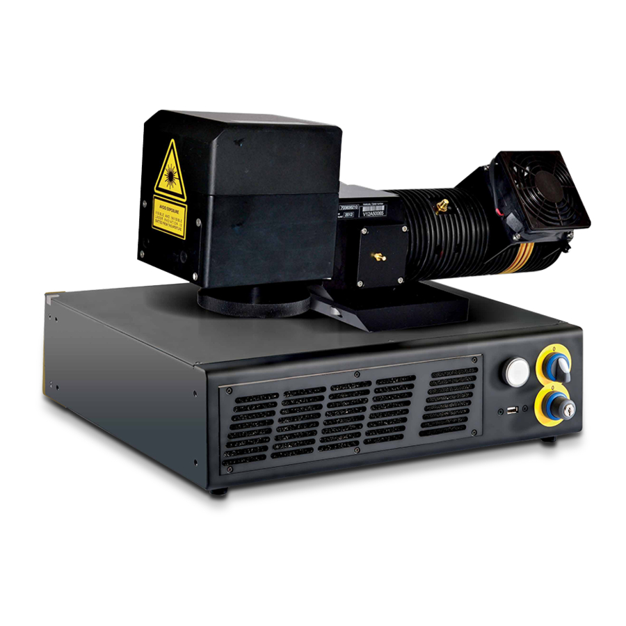
FIGURES Figure 1: Control rack and resonator with scan head..................vii Figure 2: Unpacking............................10 Figure 3: Transport............................12 Figure 4: Positioning rack..........................13 Figure 5: Vertical positioning (requires additional fixing)................. 13 Figure 6: Fixing points on rack handles (cabinet assembly)................14 Figure 7: Resonator fixing points ........................ - Page 111 Figure 39: Connecting the optical fiber to resonator..................41 Figure 40: Final closing........................... 41 Figure 41: RF cable connection........................42 Figure 42: MDR connection rack side......................43 Figure 43: MDR connection resonator side..................... 43 Figure 44: Resonator cable connection rack side................... 44 Figure 45: Resonator cable connection resonator side.
Need help?
Do you have a question about the VLASE IR 1PWX-TLS2 and is the answer not in the manual?
Questions and answers