Sign In
Upload
Manuals
Brands
Datalogic Manuals
Measuring Instruments
VLASE IR 1PWX-TLS2
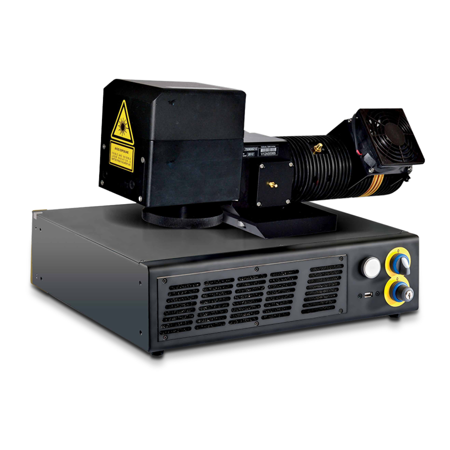
Datalogic VLASE IR 1PWX-TLS2 Manuals
Manuals and User Guides for Datalogic VLASE IR 1PWX-TLS2. We have
1
Datalogic VLASE IR 1PWX-TLS2 manual available for free PDF download: User Manual
Datalogic VLASE IR 1PWX-TLS2 User Manual (112 pages)
marking systems
Brand:
Datalogic
| Category:
Measuring Instruments
| Size: 9.95 MB
Table of Contents
Table of Contents
8
Symbols
3
Revision Index
4
Overview
6
Marking Software
6
Important Warnings
7
Figure 1: Control Rack and Resonator with Scan Head
7
Table of Contents
8
1 Contents of the Packaging
10
Unpacking
10
Figure 2: Unpacking
10
Main Hardware
11
Cable and Accessories
11
Transport
12
On Moisture Condensation
12
Figure 3: Transport
12
Fixing and Positioning
13
Figure 4: Positioning Rack
13
Figure 5: Vertical Positioning (Requires Additional Fixing)
13
Figure 6: Fixing Points on Rack Handles (Cabinet Assembly)
14
Figure 7: Resonator Fixing Points
14
Installation Environment
15
Figure 8: Rack Installation Environment
15
Figure 9: Safety Mode Example
15
Fume / Dust Extractor
16
Fan Installation
16
Figure 10: Fan Installation
16
2 Technical Specifications
17
Technical Characteristics
17
Description of the Modules
18
Resonator
18
Figure 11: Resonator View
18
Control Rack
19
Figure 12: Control Rack Front View
19
Marking Area Specification
20
Figure 13: Marking Area
21
Connectors Specifications
22
Interlock Connector
22
Figure 14: Male Panel Plug Cod. TB4M (Front View)
22
Figure 15: Female Cable Mount Connector Cod. TY4F (Solder View)
23
Interlock out Connector
24
Figure 16: Female Panel Socket Cod. 09-9766-30-04 (Front View)
24
Figure 17: Male Cable Mount Connector Cod. 09-9767-00-04 (Front View)
24
Command Box Connector (Laser Control)
25
Figure 18: Female Panel Socket Sub-D 25 (Front View)
25
Figure 19: ENABLE Signal Scheme
27
Figure 20: KEY Signal Scheme
28
Figure 21: Timing Control Signals
28
Figure 22: Timing Signals
29
Axes Connector (I/O Control)
30
Figure 23: Male Panel Socket Sub-D 25 (Front View)
30
Rs232 Connector (Com2)
31
Figure 24: Male Panel Socket Sub-D 9 (Front View)
31
Encoder Connector
32
Photocell Connector
32
Figure 25: Female Panel Socket Cod. 09-3482-87-08 (Front View)
32
Figure 26: Female Panel Socket Cod. 09-3482-87-04 (Front View)
32
Input/Output Signal Specifications
33
Connection Examples
34
Figure 27: Connection Examples
34
3 Installation and Set up
35
Connections
35
Connecting Command Box Cable
35
Figure 28: Connecting Command Box Cable
35
Connecting Interlock Cable
36
Connecting Interlock out Connector
36
Figure 29: Connecting Interlock Cable
36
Figure 30: Connecting Interlock out Connector
36
Connecting the Optical Fiber to the Control Rack
37
Figure 31: Removing the Cover Plate from the Rack
37
Figure 32: Passing the Optical Fiber through the Cable Gland
37
Figure 33: Passing the Optical Fiber through the PG Cable Gland
38
Figure 34: Connection of the Optical Fiber
38
Figure 35: Fixing the Cable Gland
39
Figure 36: Closing Cover
39
Connecting the Optical Fiber on the Resonator
40
Figure 37: Disassembling the Optical Fiber Cable Gland from the Resonator
40
Figure 38: Passing the Optical Fiber through the Cable Gland
40
Figure 39: Connecting the Optical Fiber to Resonator
41
Figure 40: Final Closing
41
Connecting Radiofrequency Cable
42
Figure 41: RF Cable Connection
42
Connecting Mdr Cable
43
Figure 42: MDR Connection Rack Side
43
Figure 43: MDR Connection Resonator Side
43
Connecting Resonator Cable
44
Figure 44: Resonator Cable Connection Rack Side
44
Figure 45: Resonator Cable Connection Resonator Side
44
Connecting Fan Cable
45
Figure 46: Resonator Fan Cable Connection
45
Connecting Power Supply Cable
46
Ground Connection
46
Figure 47: Power Supply Cable Connection
46
Figure 48: Ground Connection
46
Local Mode Connection
47
Figure 49: USB Mouse Connection
47
Figure 50: USB Keyboard Connection
47
Remote Mode Connection
48
Figure 51: VGA Monitor Connection
48
Figure 52: RJ45 Ethernet Connection
48
F-Theta Lens Protection Cap Removal
49
Figure 53: F-Theta Lens Protection Cap Removal
49
4 Use and Operation
50
Turning on Sequence
50
Figure 54: Power on
50
Figure 55: Status LED Display
50
Figure 56: Enable Command KEY
51
Figure 57: Status LED Display
51
Figure 58: Enable Command ENABLE
52
Figure 59: Status LED Display
52
Advice on Using the System
53
Local Mode Operations
54
Remote Mode Operations
54
Operating in Local Mode
56
How to Create and Edit Your First Graphic Document
57
How to Test and Engrave Your Document
60
How to Use External Signals to Engrave Your Document
62
Thermalization and Suppression of Giant Pulses
64
Figure 60: Temporal Diagram of Software Thermalization
64
5 Customize the System's Software
66
Change O.s. Language and Keyboard Layout
66
Change Lan Configuration and Ip Address
69
Change Video Setting
72
Remote Desktop Connection
74
6 Accessories
76
Control Box
76
Figure 61: Control Box (Ordering No: 985330031)
76
Marking on Fly Kit
77
Extended Length Cable Kit
77
Figure 62: Kit MOF (Ordering No: 985330027)
77
Figure 63: Extended Length Cable Kit
77
Rack Handles
78
Figure 64: Rack Handles
78
7 Technical Support
79
Seals
79
Maintenance
80
F-Theta Scan Lens Cleaning Procedure
80
Figure 65: Cleaning F-Theta Lens
80
Air Filter Cleaning Procedure
81
Figure 66: Removal of Air Filter
81
Product Support and Customer Service
82
Appendix A: Labels Identification
83
External Label Placing
85
Figure 67: Positioning of External Labels (Rack)
85
Figure 68: Positioning of External Labels (Resonator)
86
Appendix B: Standards
87
Laser Standards
87
Ce Compliance
87
Fcc Compliance
87
Appendix C: Safety Consideration According to en Iso 13489-1:2008
88
Performance Level (Pl)
88
Application Example
88
Figure 69: Determining the Required Performance Level (Plr)
88
Example Automatic Production Line
89
Safety Functions of Vlase
92
Appendix D: Laser Safety
93
Laser Radiation
94
Absorption of Laser Radiation
95
Classification and Danger Level
95
Figure 70: Eyeball Section
95
Radiation Viewing Conditions
96
Direct Viewing of the Laser Beam
96
Direct Viewing of the Beam after Mirror Reflection
96
Direct Viewing of the Beam Output by an Optical Fiber
96
Direct Viewing of the Beam after Focusing
96
Scattered Viewing of the Beam after Focusing
96
Determination and O.D. of Protection Goggles
97
Eyes and Skin Risks
99
General Safety Regulations
99
Collateral Risks
99
Appendix E: Software Upgrade
100
Appendix F: Recover the System Using Usb Recovery Disk
102
Appendix G: Mechanical Drawings
108
Figures
110
Advertisement
Advertisement
Related Products
Datalogic VLASE IR 1109-1 42 Series
Datalogic VLASE IR 1209-1 42 Series
Datalogic SG-PSB 1200
Datalogic SG-PSB 1000
Datalogic MATRIX 120 311-010 1.2MP SER+ETH WA
Datalogic MATRIX 120 311-100 1.2MP SER+USB WA 1D
Datalogic MATRIX 120 210-050 WVGA SER+USB STD SC
Datalogic UniQ 1150-1X41
Datalogic MATRIX 120 311-055 1.2 SER+USB WA PLZ SC
Datalogic MATRIX 120 311-050 1.2MP SER+USB WA SC
Datalogic Categories
Barcode Reader
Scanner
Accessories
PDA
Handhelds
More Datalogic Manuals
Login
Sign In
OR
Sign in with Facebook
Sign in with Google
Upload manual
Upload from disk
Upload from URL