Table of Contents
Advertisement
Quick Links
Advertisement
Table of Contents

Related Manuals for Datalogic AREX 401


Summary of Contents for Datalogic AREX 401
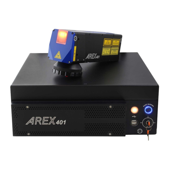
- Page 1 AREX™ 401 USER MANUAL InfraRed Fiber Laser Marker...
- Page 2 Electronic versions of this document may be downloaded from the Datalogic website (www.datalogic.com). If you visit our website and would like to make comments or suggestions about this or other Datalogic pub- lications, please let us know via the "Contact" page.
-
Page 3: Table Of Contents
TABLE OF CONTENTS PREFACE .........................VII About this Manual ......................vii Manual Conventions .......................... vii Technical Support ......................vii Support Through the Website ......................vii Warranty ........................viii CHAPTER 1. INTRODUCTION..................1 General ........................... 1 Model Description ......................2 CE Compliance ......................... 3 FCC Compliance ....................... - Page 4 CONTENTS Green Spot ........................28 Connectors Specifications ....................29 X3 - SLO (Safe Laser Off) ........................29 Control rack back panel connector ..................29 Input ............................30 Output ............................30 SAFETY_FDBK Output Status ....................31 SLO External Connector ......................32 SLO Muting Device ........................32 X1 - Command Box (Laser Control) ....................33 Control rack back panel connector ..................
- Page 5 CORDING TO EN ISO 13849-1:2015 ................98 Machine Safety ......................98 Risk Assessment ......................99 Performance Level (PL) ....................100 Datalogic Laser Markers ....................100 SLO connection diagram ....................101 Safety Functions ......................101 Example 1 ............................102 Example 2 ............................103 Example 3 ............................104...
- Page 6 CONTENTS SLO Integration example ....................105 APPENDIX C. LASER SAFETY ................106 Laser radiation ......................106 Absorption of laser radiation ..................108 Classification and danger level ..................109 Degree of risk with radiation viewing conditions ............109 Direct viewing of the laser beam ....................109 Viewing of a laser reflected beam ....................110 Viewing of direct laser beam from a fiber output ................110 Viewing of scattered laser beam ....................110...
-
Page 7: Preface
TECHNICAL SUPPORT Support Through the Website Datalogic provides several services as well as technical support through its website. Log on to (www.datalogic.com). For quick access, from the home page click on the search icon , and type in the name of the product you’re looking for. -
Page 8: Warranty
Products once sold. The Warranty Period shall be two years from the date of shipment by Datalogic, unless otherwise agreed in an applicable writing by Datalogic. Datalogic will not be liable under the warranty if the Product has been exposed or subjected to any: (1) maintenance, repair, installation, handling, packaging, transportation, storage, operation or use that is improper or otherwise not in compliance with Datalogic’s instruction;... -
Page 9: Chapter 1. Introduction
NOTE: Datalogic shall not be held responsible for any non-conforming use of laser marker of its manufacture. CAUTION: BEFORE INSTALLING AND USING THE LASER MARKER, CARE- FULLY READ THIS MANUAL. -
Page 10: Model Description
Not all combinations are available. For a com- plete list of combinations see the Models tab on the Product page of the website. LASER MARKING MACHINE E499316 DATALOGIC S.r.l. via S.Vitalino, 13 - 40012 Calderara di Reno (BO) - Italy www.datalogic.com AREX XXX-XXX Laser Type... -
Page 11: Ce Compliance
Since April 20 , 2016 the main European directives applicable to Datalogic products require inclusion of an adequate analysis and assess- ment of the risk(s). This evaluation was carried out in relation to the applicable points of the standards listed in the Declaration of Conformity. -
Page 12: Ul Compliance
INTRODUCTION UL COMPLIANCE Reading this manual prevents the operator from carrying out operations that could cause damage to himself or others. Follow-Up Service Procedure issued on 2019-03-26. AREX™ 401... -
Page 13: Laser Standards
Datalogic is available for providing to the customers all the information in its possession to help in complying with applicable standards. -
Page 14: Overview
INTRODUCTION OVERVIEW The Fiber laser marker developed and manufactured by Datalogic employs the most advanced technologies with regards to the opto-mechanical parts, the electronic con- trol of laser beam power, communication and the overall safety of the entire marker. The Arex™ 401 laser marker features a control rack and a scan head. The control rack size is standard 19"... -
Page 15: Important Warnings
Access to the internal parts of the laser marker is allowed only to authorized personnel, duly qualified and trained with regards to risks of optical and electrical nature. Datalogic declines any and all responsibility for work carried out on active parts by untrained or unauthorized personnel. -
Page 16: Chapter 2. Installation
CHAPTER 2 INSTALLATION UNPACKING CAUTION: Control rack and scan head are joined by a connection cable 3 meters long, referred as Head Cable. Control rack and scan head are NOT separable. CAUTION: Be extremely careful to not damage the connection cable between scan head and control rack. - Page 17 Figure 1: Unpacking Keep all packing materials until the laser has been inspected for completeness and dam- age. If something is missing or defective, call Datalogic (see “Technical Support” on page vii for contact details). Be sure to use the original packaging material for the transportation of this laser marker, otherwise transportation could cause malfunctions or damage.
-
Page 18: Contents Of The Packaging
INSTALLATION CONTENTS OF THE PACKAGING Control Rack Scan Head Power Supply cables Command Box Rack Fixing Brackets MUTING DEVICE External Connector Safety labels USB Drive Selector Keys Quick Reference Guide EULA Windows 10 Test report and sample test plate AREX™ 401... -
Page 19: On Moisture Condensation
ON MOISTURE CONDENSATION ON MOISTURE CONDENSATION If the laser marker is brought directly from a cold to a warm location, moisture may con- dense inside or outside the laser product. This moisture condensation may cause a mal- function of the laser marker. Note on moisture condensation Moisture may condense when you bring the laser marker from a cold place into a warm place (or vice versa) and when you use the laser marker in a humid place. -
Page 20: Fixing And Positioning
INSTALLATION FIXING AND POSITIONING CAUTION: Fix the laser marker according to instructions shown in the fig- ures. CAUTION: It is mandatory to secure the laser marker before you start marking, since improper securing or positioning may cause serious dam- age. Do not secure the laser marker in a way other than the one described in the figure. -
Page 21: Control Rack Installation
CONTROL RACK INSTALLATION CONTROL RACK INSTALLATION Horizontal installation The control rack must be positioned in a safe manner, following the recommendations below: Figure 2: Control rack horizontal positioning The control rack can be installed on a standard 19" rack cabinet using the fixing brack- ets. - Page 22 INSTALLATION Using this position the fixing brackets are aligned with the console. Figure 4: Control rack fixing brackets mounting position 1 Using this position the fixing brackets are aligned with the frontal grid panel. Figure 5: Control rack fixing brackets mounting position 2 Use this position if you want to use a pre-existing integration for AREX™...
-
Page 23: Vertical Installation
CONTROL RACK INSTALLATION Vertical installation The control rack must be positioned in a safe manner, following the recommendations below. NOTE: The feet must be removed from the bottom of the control rack and installed on the left side of the control rack using the appropriate fixing points. -
Page 24: Control Rack Mounting Screws Length
INSTALLATION Control rack mounting screws length To determine the length of the mounting screws, consider the thickness of the mount- ing plate and the thickness of the washer. Control rack 7 mm Mounting plate thickness Washer thickness M4 screw Figure 9: Length of mounting screws NOTE: Mounting holes depth is = 7mm. -
Page 25: Scan Head Installation
SCAN HEAD INSTALLATION The scan head can be installed in any orientation and must be fixed to a suitable base (not supplied by Datalogic) using the dedicated threaded holes and the high-precision slotted seats: Figure 10: Fixing points on scan head (bottom view) NOTE: All dimensions are in millimeters. - Page 26 INSTALLATION It is also possible to mount the scan head sideways using dedicated threaded holes: Figure 11: Fixing points on scan head side NOTE: All dimensions are in millimeters. AREX™ 401...
-
Page 27: Scan Head Mounting Screws Length
SCAN HEAD INSTALLATION Scan head mounting screws length To determine the length of the mounting screws, consider the thickness of the mount- ing plate and the thickness of the washer. Scan Head 4 mm Mounting plate thickness Washer thickness M5 screw Figure 12: Length of mounting screws NOTE: Mounting holes depth is = 4mm. -
Page 28: Installation Environment
INSTALLATION INSTALLATION ENVIRONMENT Control rack The control rack must be installed in a suitable environment in order to allow proper air flow and correct housing of the cables. The control rack uses a forced air cooling system: an adequate air flow is necessary to guarantee its correct cooling. -
Page 29: Scan Head
FUME / DUST EXTRACTOR Scan Head The scan head must be installed in a suitable environment in order to allow proper air flow and correct housing of the cables. The scan head uses a passive air cooling system: an adequate air flow is necessary to guarantee its correct cooling. -
Page 30: Chapter 3. Technical Specifications
CHAPTER 3 TECHNICAL SPECIFICATIONS TECHNICAL CHARACTERISTICS AREX 401 10C-X6X ELECTRICAL SPECIFICATIONS Input Voltage (main power supply) V (AC) 100 to 240 @ 50-60 Hz Max. Input Current (main power supply) 5 - 2.1 Max power LASER SOURCE SPECIFICATIONS Laser Type... - Page 31 TECHNICAL CHARACTERISTICS AREX 401 10C-X6X PHYSICAL SPECIFICATIONS 158x432x434 Control Rack dimensions (HxWxD) 6.22x17x17.1 23.5 Control Rack Weight 51.8 Control Rack IP Rating IP31 (in horizontal position, otherwise IP30) Forced Air Control Rack Cooling Rack fans: L10@40°C = 70000 h Laser source fans: L10@40°C = 65000 h...
-
Page 32: Product Description
TECHNICAL SPECIFICATIONS PRODUCT DESCRIPTION Control rack A description of the main parts of the control rack unit is provided here below: 17 18 Figure 15: Control rack overview (front and back panels view) Front panel: 1. Status LED 2. Start Marking button 3. -
Page 33: Scan Head
PRODUCT DESCRIPTION Scan head A description of the main parts of the scan head unit is provided here below: Figure 16: Scan head overview (front, rear and bottom view) 1. Status LED 2. F-Theta Scan Lens 3. External Focus Beam connector 4. -
Page 34: Marking Area Specification
TECHNICAL SPECIFICATIONS MARKING AREA SPECIFICATION Datalogic provides a wide range of laser marker models with different F-Theta scan lenses configurations. These configurations are provided to best match customer needs regarding marking field size, working distance and power density. NOTE: Contact Datalogic if other configurations are necessary. -
Page 35: F-Theta Scan Lens
MARKING AREA SPECIFICATION F-Theta Scan Lens The table below lists the standard F-Theta scan lenses currently available for Arex™ 401 10C-X6X: F-Theta Scan Lens compatibility ƒ ƒ ƒ ƒ ƒ F-THETA SCAN LENS = 160M = 254M = 254L = 330L = 420L Working Distance (WD) mm 166 ±... -
Page 36: Green Spot
TECHNICAL SPECIFICATIONS GREEN SPOT The Green Spot is an indicator integrated in the scan head able to provide a green visual feedback in the center of marking field area. Figure 18: Green Spot indicator DESCRIPTION CONFIGURATION The Green Spot indicator is not active (always OFF) The Green Spot is steady ON only when all these events are verified: •... -
Page 37: Connectors Specifications
CONNECTORS SPECIFICATIONS CONNECTORS SPECIFICATIONS X3 - SLO (Safe Laser Off) Control rack back panel connector Socket Sub-D, 15 pins, female. Figure 19: X3 - SLO connector, female panel plug (front view) SIGNAL TYPE DESCRIPTION X3.1 Power Output Isolated Auxiliary 24V DC power supply X3.2 RESERVED DO NOT CONNECT... -
Page 38: Input
TECHNICAL SPECIFICATIONS X3 - SLO Electric Diagram LASER MARKER LASER MARKER INTERLOCK_B INTERLOCK_A LASER_STOP_B LASER_STOP_A /LASER_STOP_B /LASER_STOP_A SAFETY_FDBK+ SAFETY_FDBK- Figure 20: X3 - SLO connector, electric diagram Input TECHNICAL CHARACTERISTICS Optocoupler Type 24 V DC Vtyp 15 mA @ 24 V DC Imax ≥... -
Page 39: Safety_Fdbk Output Status
CONNECTORS SPECIFICATIONS SAFETY_FDBK Output Status MARKING INTERLOCK_A INTERLOCK_B SAFETY_FDBK SYSTEM (X3.9) (X3.11) (X3.4-X3.5) ALLOWED DON’T CARE DON’T CARE CONTACT CLOSED CONTACT OPEN CONTACT OPEN CONTACT CLOSED CONTACT OPEN CONTACT CLOSED CONTACT OPEN CONTACT CLOSED CONTACT OPEN CONTACT OPEN CONTACT CLOSED CONTACT CLOSED CONTACT OPEN 1. -
Page 40: Slo External Connector
TECHNICAL SPECIFICATIONS SLO External Connector Sub-D 15 pins to terminal blocks electrical board. Figure 21: SLO External Connector SLO Muting Device NOTE: The laser marker is not equipped with a SLO Muting Device. CAUTION: Do not use the SLO Muting Device for external devices, since this will result in loss of the safety function of the machine to which this prod- uct is installed. -
Page 41: X1 - Command Box (Laser Control)
CONNECTORS SPECIFICATIONS X1 - Command Box (Laser Control) Control rack back panel connector Socket Sub-D, 25 pins, female. Figure 23: X1 - Command Box connector, female panel socket (front view) SIGNAL TYPE*** DESCRIPTION Output power Auxiliary 24V DC power supply available for EXT_ENABLE_B (max X1.1 24V_ENABLE_B supply... - Page 42 TECHNICAL SPECIFICATIONS SIGNAL TYPE*** DESCRIPTION External reference input power supply voltage for PNP output type Input power configuration: X1.16 VIN_EXT supply - NOT CONNECTED or GND: sets all digital outputs to NPN (default) - 10÷28V DC sets all digital outputs to PNP Digital Output This signal is used to know if the marking process is finished: X1.17...
-
Page 43: Muting Device
CONNECTORS SPECIFICATIONS Muting Device Sub-D, 25 pins, male, with shell. Figure 24: Command Box Muting Device provided CAUTION: If the Command Box Muting Device provided is connected, the laser marker enable is bypassed. Internal electric diagram 24V_ENABLE_B EXT_ENABLE_B EXT_24V EXT_KEY EXT_24V CONNECTOR_PRESENCE 24V_ENABLE_A... -
Page 44: X2 - Axes (I/O Control)
TECHNICAL SPECIFICATIONS X2 - Axes (I/O Control) Control rack back panel connector Plug Sub-D, 25 pins, male. Figure 26: X2 - Axes connector, male panel plug (front view) SIGNAL** TYPE*** DESCRIPTION Output Power Auxiliary 24V DC power supply available for drive input logical X2.1 EXT_24V supply... - Page 45 CONNECTORS SPECIFICATIONS SIGNAL** TYPE*** DESCRIPTION Digital Output X2.18 OUTPUT_7 (*) or DIR X PNP/NPN Generic output or X-Axis drive direction signal configurable X2.19 INPUT 9 Digital Input Generic Input X2.20 INPUT 8 Digital Input Generic Input Generic input or R-Axis home sensor input. The home search is X2.21 INPUT_7 (*) or ZERO R Digital Input...
-
Page 46: Encoder
Table 7: Encoder connector pinout (*) see “Input/Output specifications” on page 41 Photocell Control rack back panel connector Socket, M12, 4 pins female. Recommended photocell: Datalogic S51-PA-5-B01-PK; Data- logic S15-PA-5-B01-PK or equivalent. Figure 28:Photocell connector, female panel socket (front view) SIGNAL... -
Page 47: Device Port 1
CONNECTORS SPECIFICATIONS Device Port 1 Control rack back panel connector Plug, M12, 8 positions male. Figure 29: Device Port 1 connector, male panel plug (front view) SIGNAL TYPE* DESCRIPTION Power Output Auxiliary 24V DC power supply (15W max power) Ground Ground reference EXT_TRIG_#1 Digital Output Reserved output for MARVIS™... -
Page 48: Rs232 (Com3)
TECHNICAL SPECIFICATIONS RS232 (COM3) Control rack back panel connector Plug Sub-D, 9 pins, male. Figure 31: RS232 connector, male panel plug (front view) SIGNAL TYPE DESCRIPTION Input Data Carrier Detect Input Receive Data Output Transmit Data Output Data Terminal Ready Ground Ground reference Input... -
Page 49: Input/Output Specifications
INPUT/OUTPUT SPECIFICATIONS INPUT/OUTPUT SPECIFICATIONS Digital Input USING EXTERNAL POWER SUPPLY USING AUXILIARY POWER SUPPLY USER SIDE LASER MARKER SIDE USER SIDE LASER MARKER SIDE TECHNICAL CHARACTERISTICS Optocoupler Type 28 V DC Vmax 10 mA @ 24 V DC Imax ≥ 1ms (debounce) Pulse Width 0.0 V DC 0.0 V DC... -
Page 50: Digital Output
TECHNICAL SPECIFICATIONS Digital Output NPN Configuration (default) USING EXTERNAL POWER SUPPLY USING AUXILIARY POWER SUPPLY USER SIDE USER SIDE LASER MARKER SIDE LASER MARKER SIDE X1.4 OUTPUT OUTPUT X1.19 PNP Configuration External reference X1.4 10÷28V DC X1.16 X1.16 OUTPUT OUTPUT X1.19 X1.19 TECHNICAL CHARACTERISTICS... -
Page 51: Laser Marker States
LASER MARKER STATES LASER MARKER STATES Normal Operation States STATE DESCRIPTION STATUS LED This state occurs since the laser marker is SYSTEM BOOTING UP switched on until Laser Engine has been loaded and no errors occurred Blinking In this state the laser marker cannot emit IR lasers WAIT FOR START radiation and Aiming and Focus beam cannot be activated... -
Page 52: Warning State
TECHNICAL SPECIFICATIONS LASER SOURCE DESCRIPTION ERRORS This error occurs if the temperature inside the laser source is out of TEMPERATURE ERROR the operating temperature range. To reset the error, a Laser marker restart is required This error occurs if the power supply of the laser source is out of POWER SUPPLY ERROR range. -
Page 53: Control The Laser Marker States
LASER MARKER STATES Control the Laser Marker States The laser marker states can be controlled by: • Key Selector • X1 - Command Box connector Key Selector mode Controlling the laser marker states using the Key Selector on the control rack front panel requires that the input signals of the X1 - Command Box connector X1.12 (EXT_KEY), X1.8 (EXT_ENABLE_A) and X1.2 (EXT_ENABLE_B) are set to fixed HIGH level: X1 - COMMAND BOX... -
Page 54: Operating Modes
TECHNICAL SPECIFICATIONS OPERATING MODES MEASURE MODE DESCRIPTION LASER_STOP INTERLOCK SELECTOR • PC running DISABLED ENABLED • Marking not allowed • Aiming beam not allowed LASER OFF ENABLED ENABLED • Focusing beam not allowed • SAFETY LEVEL according to DISABLED proper use of safety inputs •... -
Page 55: Timing Diagrams
TIMING DIAGRAMS TIMING DIAGRAMS Turning On sequence user defined within 50ms user defined within 50ms typ 60s Figure 33: Turning On sequence timing diagram Marking control signals behavior Figure 34: Marking process timing diagram REF. NAME DESCRIPTION Minimum time duration that the START_MARKING signal must have Start Time in order to be accepted as a valid START_MARKING event Delay between the acceptance of the START_MARKING signal and the... -
Page 56: Sw_Ready Output Signal (Ready To Mark Mode)
TECHNICAL SPECIFICATIONS SW_READY output signal (Ready to Mark mode) Figure 35: SW_READY signal timing diagram MARKING_KO output signal Bad marking event Figure 36: MARKING_KO signal timing diagram SYSTEM_ALARM output signal Error event Figure 37: SYSTEM_ALARM timing diagram AREX™ 401... -
Page 57: Marvis™ I/O Signals Behavior
TIMING DIAGRAMS MARVIS™ I/O signals behavior Figure 38: MARVIS™ I/O signals behavior Safety functions behavior INTERLOCK behavior user defined within 50ms within 600ms Figure 39: INTERLOCK behavior LASER_STOP behavior user defined within 50ms within 600ms Figure 40: LASER_STOP behavior USER MANUAL... -
Page 58: Green Spot Behavior
TECHNICAL SPECIFICATIONS Green Spot behavior System Ready to Mark mode Figure 41: Green Spot: System Ready to mark Marking Confirmation mode 0.1s to 5s Figure 42: Green Spot: Marking Confirmation MARVIS™ Verification mode 0.1s to 5s Figure 43: Green Spot: MARVIS™ Verification AREX™... -
Page 59: Axes I/O Signals Behavior
TIMING DIAGRAMS Axes I/O signals behavior Figure 44: Axes I/O signals behavior REF. NAME DESCRIPTION The time that elapses between the brake release signal activation and Brake release the start of mechanical movement The time to go from minimum speed (Start speed) to working speed Ramp Time (Speed) USER MANUAL... -
Page 60: Lighter™ Suite Marking Software
Read Verify Integrated Solution) feature to seamless interact with AutoID code reader for in-line validation of marked traceability codes. MARVIS™ connects Datalogic MATRIX™ N-series reader with the laser marker, enabling controlling from one single interface and enhancing individual products’ performances. - Page 61 LIGHTER™ SUITE MARKING SOFTWARE Connectivity The Lighter™ Suite allows OEMs and Machine builders to develop a complete and cost effective Laser Marking Station, based on embedded hardware and software resources (such as STAND ALONE mode) or to design an advanced Laser Marking Solution able to control machinery over a simple Ethernet connection with a supervisor computer (MAS- TER-SLAVE mode).
-
Page 62: Chapter 4. Set Up
CHAPTER 4 SET UP CONNECTIONS The laser marker connections are described here below. Follow the operations as described. CAUTION: Control rack and scan head are joined by a connection cable 3 meters long. Control rack and scan head are NOT separable. Connecting X1 - Command Box connector The X1 - Command Box connector must always be inserted with proper signals provided in order to use the laser marker. -
Page 63: Connecting X3 - Slo Connector
CONNECTIONS Connecting X3 - SLO connector The X3 - SLO connector must always be inserted with proper signals provided in order to use the laser marker. The absence of such connector blocks the laser emission. WARNING: If built, do not use the SLO Muting Device for external devices, since this will result in loss of the safety function of the machine to which this product is installed. -
Page 64: Connecting Power Supply Cable
SET UP Connecting Power Supply cable Connect the Power Supply cable using the cord retention system. NOTE: The locking mechanism is released again by pressing the release lever. Thanks to its luminous bright yellow color, it is easily recognizable and distinguishes this system from conventional mains connections. Figure 47: Connecting Power Supply cable Connecting the Earth Ground To ensure high electrical noise immunity it is strongly recommended to connect the chassis... -
Page 65: Local Mode Control Connections
CONNECTIONS Local Mode Control connections To use the laser marker in “Local Mode Control” it is necessary to install a mouse, keyboard and monitor. Connect the monitor and input devices to laser marker as shown below: Figure 49: Connecting the mouse Figure 50: Connecting the keyboard USER MANUAL... - Page 66 SET UP Figure 51: Connecting the monitor NOTE: Minimum monitor resolution 800 x 600 (VGA standard). AREX™ 401...
-
Page 67: Remote Mode Control Connection
CONNECTIONS Remote Mode Control connection To use the laser marker in “Remote Mode Control” it is necessary to connect a network cable: Figure 52: Connecting LAN port NOTE: The LAN ports are configured by default with a fixed IP Address and Subnet Mask: - LAN 1 Default IP address: 192.168.1.10 - LAN 2 Default IP address: 192.168.3.10... -
Page 68: F-Theta Scan Lens Protection Cap Removal
SET UP F-THETA SCAN LENS PROTECTION CAP REMOVAL Remove the F-Theta scan lens protection cap before marking operation: Figure 53: F-Theta scan lens protection cap removal CAUTION: Marking with the lens protection cap in place could result in damage to the laser marker. Laser markers with M F-Theta scan lenses are provided by default with the F-Theta pro- tective cap for M lenses (see “F-Theta protective cap for M lenses”... -
Page 69: Chapter 5. Use And Operation
CHAPTER 5 USE AND OPERATION Before turning on the laser marker, be sure that the laser marker is connected as previ- ously described. Check the presence of: • Voltage power supply connection • X3 - SLO connection • X1 - Command Box connection WARNING: If built, do not use the SLO Muting Device for external devices, since this will result in loss of the safety function of the machine to which this product is installed. -
Page 70: Turning On Sequence
USE AND OPERATION TURNING ON SEQUENCE The laser marker states can be controlled by: • Key Selector (see “Sequence using Key Selector” on page 62) • X1 - Command Box connector (see “Sequence using X1 - Command Box connec- tor” on page 65) Sequence using Key Selector CAUTION: Controlling the laser marker states using the Key Selector on the control rack front panel requires that the input signals of the X1 - Com-... - Page 71 TURNING ON SEQUENCE Rotate the key selector one-step to “1” position: Figure 57: Key selector in “1” position The status LED on the control rack and the status LED on the scan head are steady orange. The laser marker is in STANDBY SHUTTER CLOSED state. Figure 58: Standby Shutter closed state USER MANUAL...
- Page 72 USE AND OPERATION Rotate the key selector one-step to “2” position: Figure 59: Key selector in “2” position The status LED on the control rack and status LED on the scan head will turn red. The laser marker is in READY state. Figure 60: Ready state AREX™...
-
Page 73: Sequence Using X1 - Command Box Connector
TURNING ON SEQUENCE Sequence using X1 - Command Box connector CAUTION: Controlling the laser marker states using the X1 - Command Box connector on the control rack back panel requires that the Key Selector is set to fixed position LASER_ON. Turn ON the main power supply switch in the back panel of the control rack. - Page 74 USE AND OPERATION Set the Command box input signals as in the table below: X1 - COMMAND BOX STATE STATUS LED INPUT STATE SELECTOR EXT_KEY HIGH READY* EXT_ENABLE_A HIGH EXT_ENABLE_B HIGH Steady The status LED on the control rack and status LED on the scan head will turn red. The laser marker is in READY state.
-
Page 75: Chapter 6. Customize The Laser Marker Software
OS parameters other than those indicated in the User Manual, as well as the installation of HW and / or SW not authorized or supplied by Datalogic can adversely affect system stability and marking performance. In case of system instability or performance degradation following SW / HW modifications, restore the original laser marker configuration (see Appendix B ). -
Page 76: How To Use The System Protection Tool
By right-clicking the tray-bar icon then, “Configure” • Double-clicking the tray-bar icon • From Start Menu\Datalogic\System Protection Enable the system protection NOTE: When the System Protection is enabled any change or deletion on the C:\ drive will be restored after system reboot. - Page 77 SYSTEM PROTECTION • Wait for system reboot CAUTION: DO NOT turn OFF or UNPLUG the system while Windows® is shut- ting down. • Check if the Tray-bar icon color is GREEN (protection enabled) Disable the system protection CAUTION: When the System Protection is disabled the system is not pro- tected against disk corruption or malware attacks.
- Page 78 CUSTOMIZE THE LASER MARKER SOFTWARE • Wait for system reboot CAUTION: DO NOT turn OFF or UNPLUG the system while Windows® is shut- ting down. • Check if the Tray-bar icon color is RED (protection disabled) AREX™ 401...
-
Page 79: Change O.s. Language And Keyboard Layout
CHANGE O.S. LANGUAGE AND KEYBOARD LAYOUT CHANGE O.S. LANGUAGE AND KEYBOARD LAYOUT The laser marker allows you to customize the operating system changing the language used in menus, dialogs and languages you can use to enter text and keyboard layout. The following languages are pre-installed in the system: Chinese (PRC), Chinese (Tai- wan), English (United States), French (France), German (Germany), Italian (Italy), Japa- nese (Japan), Korean (Korea), Spanish (Spain). - Page 80 CUSTOMIZE THE LASER MARKER SOFTWARE 6. Select the Windows display language: 7. Click on the Input Indicator icon in the taskbar 8. Select the keyboard layout from the list: 9. Close all the open windows AREX™ 401...
- Page 81 CHANGE O.S. LANGUAGE AND KEYBOARD LAYOUT 10. Enable system protection (see “Enable the system protection” on page 68) CAUTION: When the System Protection is disabled the system is not pro- tected against disk corruption or malware attacks. 11. Wait for the operating system to restart 12.
-
Page 82: Change The Lan Configuration And Ip Address
CUSTOMIZE THE LASER MARKER SOFTWARE CHANGE THE LAN CONFIGURATION AND IP ADDRESS The operating system allows you to change the LAN configuration and IP address. NOTE: In order to perform this setting it is necessary to connect mouse, keyboard and monitor to the laser marker (see “Local Mode Control con- nections”... - Page 83 CHANGE THE LAN CONFIGURATION AND IP ADDRESS 6. Click on Change adapter options 7. In the Network Connections window double click on the desired Network icon: USER MANUAL...
- Page 84 CUSTOMIZE THE LASER MARKER SOFTWARE 8. In the Network Properties window double click on Internet Protocol Version 4 (TCP/IPv4) and edit the IP address and/or subnet mask. 9. Close all the open windows 10. Enable system protection (see “Enable the system protection” on page 68) CAUTION: When the System Protection is disabled the system is not pro- tected against disk corruption or malware attacks.
-
Page 85: Change The Video Setting
CHANGE THE VIDEO SETTING CHANGE THE VIDEO SETTING The operating system allows you to change the Video setting. NOTE: In order to perform this setting it is necessary to connect mouse, keyboard and monitor to the laser marker (see “Local Mode Control con- nections”... - Page 86 CUSTOMIZE THE LASER MARKER SOFTWARE 6. Change the Display settings 7. Close all the open windows 8. Enable system protection (see “Enable the system protection” on page 68) CAUTION: When the System Protection is disabled the system is not pro- tected against disk corruption or malware attacks.
-
Page 87: Remote Desktop Connection
REMOTE DESKTOP CONNECTION REMOTE DESKTOP CONNECTION To connect the laser marker to a remote Windows® based computer, follow these steps: 1. Turn on the laser marker 2. Make sure that both laser marker and remote computer are connected to the LAN 3. -
Page 88: Chapter 7. Accessories
CHAPTER 7 ACCESSORIES The accessories listed here below are described for information purposes only, and are not necessarily included in the packaging. The minimum contents of the packaging include the main hardware, cables and keys. For additional information, please see “Contents of the packaging”... -
Page 89: Remote Start Foot Switch
REMOTE START FOOT SWITCH REMOTE START FOOT SWITCH This accessory is used to provide the START_MARKING signal to the laser marker when the pedal is pressed by the operator. Figure 65: Remote Start Foot Switch (ordering no: 985350035) NOTE: Refer to Remote Start Foot Switch instruction manual for more information. -
Page 90: Db25-To-Free Leads Cable
ACCESSORIES DB25-TO-FREE LEADS CABLE This accessory allows an easier integration of the laser marker: the Command Box con- nector signals are all available on the free leads side of the cable, labeled with cable tags. Figure 67: DB25-to-free leads cable (ordering no. 985350032) MARVIS™... -
Page 91: Marvis™ Mounting Bracket For M And L Lenses
MARVIS™ MOUNTING BRACKET FOR M AND L LENSES MARVIS™ MOUNTING BRACKET FOR M AND L LENSES This accessory is used to properly fix the MATRIX™-N to the scan head in a MARVIS™ application (suitable for M and L F-Theta scan lenses). Figure 69: MARVIS™... -
Page 92: F-Theta Protective Cap For M Lenses
ACCESSORIES F-THETA PROTECTIVE CAP FOR M LENSES Easy to install, easy to replace; simplifies preventive/periodic maintenance cleaning operation on F-Theta scan lens and allow no-stop operations. • Ensure complete IP64 protection • Protect expensive lens from dust and scratches • Suitable for 160M and 254M F-Theta scan lenses Figure 71: F-Theta protective cap (ordering no.93ACC0371) NOTE: The Protective Cap guarantees IP64 protection grade. -
Page 93: Chapter 8. Technical Support
The laser marker has seals in some areas. The seals must not be broken or removed for any reason. The sealed parts may be opened only and exclusively by Datalogic. Breaking these seals voids the warranty on the entire laser marker. -
Page 94: Maintenance
TECHNICAL SUPPORT MAINTENANCE The ordinary maintenance program of the laser marker includes only simple operations. Some operations consist in a mere “check” of the operating condition. The maintenance activities must be done in compliance with the legal directives regard- ing the safety rules during these operations. The following parts/functions have to be controlled periodically: COMPONENT TYPE OPERATION INTERVALS... -
Page 95: Air Filter Cleaning Procedure
MAINTENANCE Air filter cleaning procedure Procedure: 1. Turn off key switch on controller unit 2. Disconnect AC power cable 3. Unscrew grid panel screws and remove it 4. Remove filter Figure 74: Removal of air filter 5. Clean filter with compressed air or with neutral detergent and air-dry it 6. -
Page 96: Troubleshooting
TECHNICAL SUPPORT TROUBLESHOOTING If a problem occurs during operation, first check the following troubleshooting. If you cannot fix the problem, contact Datalogic Customer Service (see “Technical Support” on page vii). Service Interface The laser marker is equipped with a Service Interface integrated in Lighter™ Laser Con- figuration - Service useful for service purpose. - Page 97 TROUBLESHOOTING LASER SOURCE INFO INFO TYPE DESCRIPTION Serial Number Source serial number Counter of the laser source working hours expressed in Source Working Hour hours and minutes Counter of the source diode working hours expressed in Diode Working Hours hours and minutes. The counter starts to count every time the laser marker is in READY state This counter is incremented every time the Laser source Temperature Error...
-
Page 98: List Of Warning And Error States
The temperature Temperature error Blinking RED System Error must not exceed the operative limit Scan Head Contact Datalogic Technical Support Connection error Check the temperature of the environment where the control Source Temperature rack is placed. The temperature... -
Page 99: List Of Problems Related To Laser Marker States
“Marking Area Specification” on page 26 Check that the laser parameters set in the layout are appropriate for the material to Incorrect laser parameters be marked. Contact Datalogic Technical Support Check the laser marker state is set to Incorrect laser marker state... - Page 100 TECHNICAL SUPPORT PROBLEM DESCRIPTION POSSIBLE CAUSE ACTION Check that the X1.13 (STOP_MARKING) STOP_MARKING signal is active signal on the X1 - Command Box connec- tor is not set to HIGH level - Check the X1.11 (START_MARKING) sig- nal on the X1 - Command Box connector (see “X1 - Command Box (Laser Control)”...
- Page 101 TROUBLESHOOTING PROBLEM DESCRIPTION POSSIBLE CAUSE ACTION Check that the F-Theta scan lens protec- F-Theta Lens protection not removed tion has been removed The laser marker is provided with a sys- tem that prevent diode wear turning of the Aiming Beam Standby time expired diode when the Aiming Beam Standby time expired.
-
Page 102: Remote Assistance
TECHNICAL SUPPORT REMOTE ASSISTANCE The laser marker is equipped with a remote connection tool that can be used for diag- nostic purposes by Datalogic technical support. NOTE: The laser marker must be connected to the Internet. AREX™ 401... -
Page 103: Appendix Alabels
LABELS LABELS LABEL DESCRIPTION LASER MARKING MACHINE Identification label E499316 DATALOGIC S.r.l. via S.Vitalino, 13 - 40012 Calderara di Reno (BO) - Italy www.datalogic.com Warning laser logotype Laser Label (scan head) (*) Aperture Label DANGER Label for non-interlock protective housing... -
Page 104: Positioning Of External Labels
(*) Maximum output of laser radiation as per definition 3.55 of IEC60825-1 considering single fault conditions. POSITIONING OF EXTERNAL LABELS Positioning of labels on the control rack LASER MARKING MACHINE E499316 DATALOGIC S.r.l. via S.Vitalino, 13 - 40012 Calderara di Reno (BO) - Italy www.datalogic.com 2xT6.3 A Figure 75: External labels rack location AREX™ 401... -
Page 105: Positioning Of Labels On The Scan Head
SAFETY LABELS IN LOCAL LANGUAGES Positioning of labels on the scan head Figure 76: External labels Scan Head location SAFETY LABELS IN LOCAL LANGUAGES The laser marker is provided by default with laser labels and labels for non-interlock protective housing in Chinese and English language already attached to the product. Additional labels in French, Swedish, German, Italian, Spanish and Korean languages are provided with the laser marker. -
Page 106: Appendix B. Understanding Slo: Safe Laser Off Safety Considerations Ac- Cording To En Iso 13849-1:2015
APPENDIX B UNDERSTANDING SLO: SAFE LASER OFF SAFETY CONSIDERATIONS ACCORDING TO EN ISO 13849-1:2015 MACHINE SAFETY The European Community Directives establish that industrial machinery should not present a risk for workers and operators. The manufacturers should retain full responsi- bility for certifying the conformity of their machinery to the provisions of Machine Directive. -
Page 107: Risk Assessment
RISK ASSESSMENT RISK ASSESSMENT Core of the Machine Directive are “Risk Assessment” and “Risk Reduction” process. EN ISO 12100:2010 is aimed to support manufacturers during Risk Assessment. Machinery must be designed to be operated, adjusted and maintained without putting persons at risk when these operations are carried out. Risk Assessment must also taking into account any reasonably foreseeable misuse of the system. -
Page 108: Performance Level (Pl)
The Machinery Directive 2006/42/UE, EN 13849-1 and EN ISO 11553-1 are NOT applica- ble to Datalogic Laser Markers. Datalogic, in order to help customers in their approval process, as a voluntary act, has applied in its laser marker, where possible, some points of above mentioned regula- tions. -
Page 109: Slo Connection Diagram
SLO CONNECTION DIAGRAM SLO CONNECTION DIAGRAM INPUT LOGIC OUTPUT SLO is one of the components of the Protective System and Equipment. SLO is intended to be used in combination with safety PLC or safety relays. SAFETY FUNCTIONS SAFETY FUNCTION PHYSICAL INTERFACE Number of Channels: 1 SF.1: Enable Category: B... -
Page 110: Example 1
UNDERSTANDING SLO: SAFE LASER OFF SAFETY CONSIDERATIONS ACCORDING TO EN ISO 13849-1:2015 Example 1 Risk Analysis of a fully automatic laser processing machine that operates only when pro- tection system is disengaged. • Operative cycle: 500 pcs/hour, 3 shifts (8h/shift) 350 days/year •... -
Page 111: Example 2
SAFETY FUNCTIONS Example 2 Risk Analysis of a fully automatic laser processing machine that operates only when pro- tection system is disengaged. • Operative cycle: 500 pcs/hour, 3 shifts (8h/shift) 350 days /year • Dedicated enclosures prevent laser emission also during parts loading / unloading •... -
Page 112: Example 3
UNDERSTANDING SLO: SAFE LASER OFF SAFETY CONSIDERATIONS ACCORDING TO EN ISO 13849-1:2015 Example 3 Risk Analysis of a manual loading laser processing machine. • Operative cycle: 600 pcs/hour (load every minute) • Dedicated enclosures prevent laser emission during laser processing •... -
Page 113: Slo Integration Example
SLO INTEGRATION EXAMPLE SLO INTEGRATION EXAMPLE USER MANUAL... -
Page 114: Appendix C. Laser Safety
APPENDIX C LASER SAFETY The following information is provided in compliance with regulations set by Interna- tional Authorities, and it refers to proper use of the laser marker. LASER RADIATION Laser radiation is form of electromagnetic emission in the wavelength range from the ultraviolet (e.g. - Page 115 LASER RADIATION WARNING: This laser marker is classified as Class 4. Class 4 Lasers can cause damage, not only from direct or reflected laser radiation, but also from scattered radiation. These lasers cause significant risk of irreversible damage to human eye and skin as well as risk of ignition and fire of flam- mable materials, even at long distances form laser radiation output aper- ture.
-
Page 116: Absorption Of Laser Radiation
LASER SAFETY ABSORPTION OF LASER RADIATION Human tissues absorbs electromagnetic radiation in different ways depending on tissue characteristics and the wavelength of the radiation. Certain wavelengths may be trans- mitted or absorbed, in different levels, by the human tissue. In the specific case of the eye, the Cornea and Crystalline lens allows most of the radiation within the wavelength range of 400nm to 1400nm to pass a reach the retina (where are the vision sensors). -
Page 117: Classification And Danger Level
CLASSIFICATION AND DANGER LEVEL CLASSIFICATION AND DANGER LEVEL Regulations have established different classes of Lasers, based on their ability to cause human injury. These classes ranges from Class 1 (basically safe in all conditions) to Class 4 (dangerous in several conditions). Lasers that can produce risk to human being, not only from direct or reflected radiation but also from scattered radiation, belong to Class 4. -
Page 118: Viewing Of A Laser Reflected Beam
LASER SAFETY Viewing of a laser reflected beam This may occur when beam is reflected on a mirror surface. This type of viewing is as danger for human eye as direct viewing of the laser beam. WARNING: Do not look to reflected laser beam. Individual Protection Devices such goggles may only provide protection for a short period of time and thus do not warrant protection for exposure to reflected laser radia- tion. -
Page 119: Determination And O.d. Of Protection Goggles
N.O.H.D. DETERMINATION AND O.D. OF PROTECTION GOGGLES N.O.H.D. DETERMINATION AND O.D. OF PROTECTION GOGGLES In order to determine the characteristics of the protection goggles, it is essential to determine the characteristics of the laser radiation, knowing its optical path, the dimen- sions of the beam and its divergence. -
Page 120: En207 And En208
LASER SAFETY EN207 AND EN208 The O.D. value specifies the attenuation factor that the filter material theoretically has on the beam. However it does not specify the damage threshold of the filter material! The filter material may not be able to withstand the power of a particular laser and may fail instantaneously and result in serious eye injury. -
Page 121: Eyes And Skin Risks
Datalogic shall not be held liable for any damage caused by inadequate work from non-authorized personnel. CAUTION: Only Datalogic authorized personnel, who have been trained and instructed on the electrical and optical risks, is allowed to access the internal parts of the scan head. -
Page 122: Appendix D. Using Marking Software
APPENDIX D USING MARKING SOFTWARE HOW TO CREATE AND EDIT GRAPHICS LAYOUT NOTE: This example considers that the laser marker is controlled in Key Selector mode (see “Key Selector mode” on page 45). In “WAIT FOR START” state, double click the Laser Editor icon to start the layout editor application. - Page 123 HOW TO CREATE AND EDIT GRAPHICS LAYOUT Click on the Text String icon in the Object toolbar to add a string object to the layer: Objects toolbar: it allows adding objects to the cur- rent document Edit String properties such as value, font, style, etc. using the Properties browser: Properties browser: give information about...
- Page 124 USING MARKING SOFTWARE Edit Filling properties such as filling type, interline, etc. using the Properties browser: NOTE: Consult Lighter™ software user's manual for a proper use of the same. AREX™ 401...
-
Page 125: How To Test And Mark Layout
HOW TO TEST AND MARK LAYOUT HOW TO TEST AND MARK LAYOUT In “STANDBY SHUTTER CLOSED” state, press Limits All button in the Laser Toolbar to adjust the object position in the marking field: Limits function: displays the bounding box of the object(s) present in the document. - Page 126 USING MARKING SOFTWARE In “READY” state, adjust the Laser parameters using the Properties browser: Press the Send Marking button in the Laser Toolbar AREX™ 401...
-
Page 127: How To Use Command Box Signals To Mark Layout
HOW TO USE COMMAND BOX SIGNALS TO MARK LAYOUT HOW TO USE COMMAND BOX SIGNALS TO MARK LAYOUT Automate the marking process allowing documents to be marked using external X1.11 (START_MARKING) and X1.13 (STOP_MARKING) signals, which can be generated by PLC or other external devices. - Page 128 USING MARKING SOFTWARE Select the document from the list and click on the To Auto Mode button: Auto/Manual The laser marker is ready to mark the document using external X1.11 (START_MARK- ING) and X1.13 (STOP_MARKING) signals: NOTE: Consult Lighter™ software user's manual for a proper use of the same.
-
Page 129: Appendix E. Marking Software Upgrade
APPENDIX E MARKING SOFTWARE UPGRADE HOW TO UPDATE THE MARKING SOFTWARE This document describes how to update the Lighter™ Suite software version. Before updating the software, disable system protection (see “Disable the system protec- tion” on page 69). CAUTION: When the System Protection is disabled the system is not pro- tected against disk corruption or malware attacks. - Page 130 MARKING SOFTWARE UPGRADE 5. Press Next to continue: 6. Press I Agree to continue: 7. Check “I accept the terms of the License Agreement” and press Next to continue: AREX™ 401...
- Page 131 HOW TO UPDATE THE MARKING SOFTWARE 8. Choose the INTERACTIVE installation type and press Next to continue: 9. Choose the components to install and press Next to continue: 10. Do not change the destination folder and press Install to continue: USER MANUAL...
- Page 132 MARKING SOFTWARE UPGRADE 11. Press OK to uninstall the old Lighter™ Suite version 12. Press Next to continue: 13. Select the components of the old Lighter™ Suite version to remove and press Unin- stall: AREX™ 401...
- Page 133 HOW TO UPDATE THE MARKING SOFTWARE 14. Wait until the uninstallation is complete and press Close to continue: 15. Lighter Suite will be installed. Press Finish to complete the procedure: 16. If Lighter™ Suite update includes any control board updates follow the procedure below otherwise jump to step 17: •...
- Page 134 MARKING SOFTWARE UPGRADE 17. Open the System Protection tool GUI - Click the ENABLE button - A message advise the User to confirm the new setting. Press YES to enable Sys- tem Protection - A message advise the User that the system will be rebooted. Press NO to con- tinue - Shut down the system: - wait until the operating system shuts down (black screen)
-
Page 135: Appendix F. Recover The Laser Marker
APPENDIX F RECOVER THE LASER MARKER OVERVIEW The laser marker is provided with a RECOVERY partition able to restore the system to the factory settings. The RECOVERY procedure should be used if the Operating System is corrupted or disks are corrupted. HOW TO RECOVER THE LASER MARKER CAUTION: All existing data in the laser marker will be overwritten. -
Page 136: Recover The System
RECOVER THE LASER MARKER Recover the system • Turn ON the laser marker • Wait for 'Choose an operating system' menu to appears • Select 'Change defaults or choose other options' using TAB key and then press ENTER key • The Options screen will be shown •... - Page 137 HOW TO RECOVER THE LASER MARKER • Select 'Troubleshoot' using TAB key and then press ENTER key • The Troubleshoot menu will be shown • Select 'Advanced Options' using TAB key and then press ENTER key • The Advanced options menu will be shown USER MANUAL...
- Page 138 RECOVER THE LASER MARKER • Select 'System Image Recovery' using TAB key and then press ENTER key • Enter the password ' ' and press CONTINUE AREX™ 401...
- Page 139 HOW TO RECOVER THE LASER MARKER • Select 'Use the latest available system image (recommended)' • Press NEXT to continue • Press NEXT to continue USER MANUAL...
- Page 140 RECOVER THE LASER MARKER • Press FINISH to continue • Press YES to continue AREX™ 401...
- Page 141 HOW TO RECOVER THE LASER MARKER • Wait for disks restoring • The system will restart automatically USER MANUAL...
-
Page 142: New Hardware Configuration
RECOVER THE LASER MARKER NEW HARDWARE CONFIGURATION • After the restart, the system will perform the New Hardware Configuration pro- cedure • Wait for the end of the procedure • The system will restart automatically CAUTION: DO NOT turn OFF or UNPLUG the laser marker while Windows® is restarting! AREX™... -
Page 143: Customize The Marking Software
The custom Laser.inz file is present in the USB drive (see “Contents of the packaging” on page 10). If the USB drive was lost, contact Datalogic. See “Technical Support” on page vii. • After the restart, an error message will advise you that Lighter™ initialization file is not present. - Page 144 RECOVER THE LASER MARKER • Navigate to the folder Test Layouts on the USB drive, select the right test layout files depending on the laser marker model and copy them to D:\DATA\DOCS\LAY- OUTS • Shut down the operating system: CAUTION: DO NOT turn OFF or UNPLUG the laser marker while Windows® is shutting down! •...
-
Page 145: Appendix G. Mechanical Drawings
APPENDIX G MECHANICAL DRAWINGS USER MANUAL... -
Page 146: Control Rack
MECHANICAL DRAWINGS CONTROL RACK NOTE: Please refer to Datalogic website for detailed drawings. AREX™ 401... -
Page 147: Scan Head
SCAN HEAD SCAN HEAD NOTE: Please refer to Datalogic website for detailed drawings. USER MANUAL... - Page 148 © 2021-2022 Datalogic S.p.A. and /or its affiliates • All rights reserved • Without limiting the rights under copyright, no part of this documentation may be repro- duced, stored in or introduced into a retrieval system, or transmitted in any form or by any means, or for any purpose, without the express written permission of Data- logic S.p.A.
Need help?
Do you have a question about the AREX 401 and is the answer not in the manual?
Questions and answers