Datalogic Smart-VS Quick Reference Manual
Hide thumbs
Also See for Smart-VS:
- Product reference manual (52 pages) ,
- Product reference manual (84 pages)
Table of Contents
Advertisement
Available languages
Available languages
Quick Links
Smart-VS
QUICK REFERENCE GUIDE
Download the Smart-VS Product
Reference Guide by reading
the QR code here or see the
paragraph below.
SUPPORT THROUGH THE WEBSITE
Datalogic provides several services as well as technical
support through its website.
Log on to www.datalogic.com.
For quick access, from the home page click on the
search icon, and type in the name of the product you're
looking for. This allows you access to download Data
Sheets, Manuals, Software & Utilities, and Drawings.
Hover over the Support & Service menu for access to
Services and Technical Support.
INSTALLATION PROCEDURE
1. Physically mount the Smart-VS device.
2. Make the necessary electrical connections.
3. Configure the device using the embedded HMI or
the Smart-VS WebApp by connecting to the device
via Ethernet. The WebApp is accessible opening an
Internet browser (Google Chrome is recommended)
and entering the device IP address 192.168.3.100
in the address bar.
HMI INTERFACE
NO GOOD object
• in Teach phase: blinking, NO GOOD object
teaching
• in Run phase: NO GOOD object detected
• for future use
Trigger
• in Teach phase: trigger input status
• in Run phase: trigger received
GOOD object
• in Teach phase: blinking, GOOD object
teaching
• in Run phase: GOOD object detected
Run
• steady: device in Run phase
• blinking: Teaching required
BUTTON TEACHING PROCEDURE
The Run LED will blink until the Teaching procedure is
entered (e.g. device factory default).
Long press (> 4s, until the red LED on HMI lights up)
the HMI Button to enter the Teaching procedure.
1. GOOD objects required to be
taught (green LED and green
spot blink).
2. Place the GOOD object in
front of the Aiming System.
3. Place
the
trigger
sensor
properly. The Trigger LED
indicates object detection.
4. Short press (< 1s) the HMI
Button to acquire the image.
More
than
one
GOOD
object can be acquired.
It
is suggested to acquire one
image
per
GOOD
object
instance. Camera parameters
are auto-adjusted on the first
acquisition only.
5. Long press (
> 4s, until the red
LED on HMI lights up
) the
HMI Button to start acquiring
NO GOOD objects. Red LED
and red spot start blinking.
6. Place the NO GOOD object
in front of the Aiming System.
Check the Trigger LED.
7. Short press (< 1s) the HMI
Button to acquire the image.
More than one NO GOOD
object can be acquired.
8. Long press (
> 4s, until the
red LED on HMI lights up
)
the HMI Button to enter the
automatic learning procedure
(LEDs game). At the end,
the device will enter the Run
Phase.
The Teaching procedure can also be
entered when in Run phase: press the
HMI Button for 2s (yellow LED on HMI) for
incremental teaching or 4s (red LED on
HMI) to cancel and re-teach. Refer to the
NOTE
Product Reference Guide for more details.
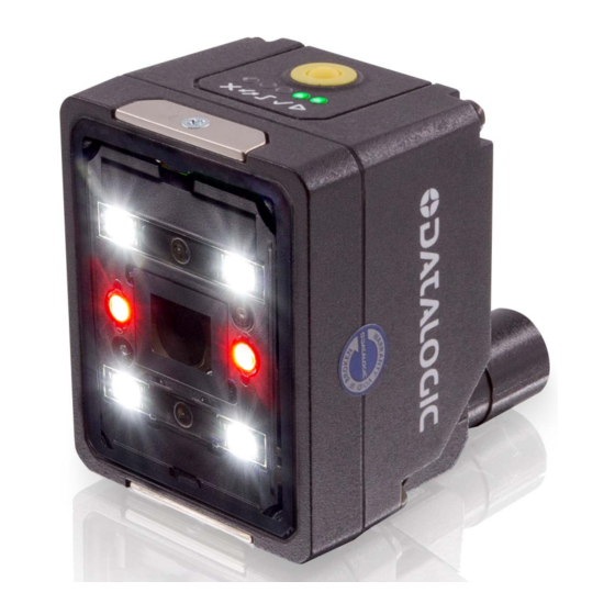
1
2
3
4
1. Bracket Mounting Holes (2)
2. Power On LED
3. Ethernet Connection LED
4. 90° Rotating Connector Block
5. HMI Interface
6. Ethernet Connector
CAB-GD03 M12-17P 3M power and
I/O cable, isolated wires (95A900052)
CAB-GD05 M12-17P 5M power and
I/O cable, isolated wires (95A900053)
M12 17-pin Power, and I/O Connector Pinout
(9 stripped wires)
Pin
Color
Name
Function
1
Brown
Vdc
PWR supply input voltage +
PWR supply input voltage -
2
Blue
GND
Chassis
Connector case provides
electrical
connection
chassis
6
Yellow
I1A *
Trigger Input A
5
Pink
I1B *
Trigger Input B
13
Green
I2A *
Remote Teach A
3
White
I2B *
Remote Teach B
9
Red
O1 **
Data Valid (default is Push-
Pull)
8
Gray
O2 **
GOOD Output (default is
Push-Pull)
16
Black
O3 **
NO-GOOD Output (default
is Push-Pull)
*
Polarity insensitive
**
Short-circuit protected and
software programmable
For proper installation, it is recommended
to trim out all unused wires.
WARNING
11
7
8
6
9
5
10
7. Power - I/O Connector
8. Lens
9. LED Aiming System
10. Red Spot (NO GOOD)
11. Green Spot (GOOD)
12. White Polarized Illuminators
CAB-GD03 M12 F/L 3M Free wires
CAB-GD05 M12 F/L 5M Free wires
CAB-GD10 M12 F/L 10M Free wires
M12 17-pin Power, and I/O Connector Pinout
(17 stripped wires)
Pin
Color
Name
Function
1
Brown
Vdc
PWR supply input voltage +
PWR supply input voltage -
2
Blue
GND
Chassis
Connector case provides
to
electrical
chassis
6
Yellow
I1A *
Trigger Input A
5
Pink
I1B *
Trigger Input B
13
I2A *
White/Green
Remote Teach A
3
White
I2B *
Remote Teach B
9
Red
O1 **
Data Valid (default is Push-
Pull)
8
Gray
O2 **
GOOD Output (default is
Push-Pull)
16
Yellow/Brown
O3 **
NO-GOOD Output (default
is Push-Pull)
12
connection
to
Advertisement
Table of Contents

Related Manuals for Datalogic Smart-VS


Summary of Contents for Datalogic Smart-VS
- Page 1 CAB-GD05 M12 F/L 5M Free wires CAB-GD05 M12-17P 5M power and and red spot start blinking. the Smart-VS WebApp by connecting to the device I/O cable, isolated wires (95A900053) CAB-GD10 M12 F/L 10M Free wires via Ethernet. The WebApp is accessible opening an 6.
- Page 2 Electrical Features Smart-VS is covered by one or more of the following patents: the limits for a Class A digital device, pursuant to part 15 of the FCC Rules. These limits are designed to provide Power...
- Page 3 GOOD davanti al sistema di SUPPORTO VIA SITO WEB puntamento. 3. Posizionare correttamente Sul sito di Datalogic sono disponibili diversi servizi e il supporto il sensore di trigger. Il LED tecnico. trigger indica il rilevamento Accedere a www.datalogic.com. dell'oggetto.
- Page 4 Potenza rispetto della normativa FCC, parte 15. Lo scopo di tali limiti Smart-VS è coperto da uno o più dei seguenti brevetti: è quello di fornire una ragionevole protezione contro le Tensione di alimentazione (Vcc) da 10 a 30 Vcc interferenze dannose quando l'apparecchiatura è...
- Page 5 长按(> 4秒,直到 HMI 上的红色 LED 亮起)HMI 按 钮进入示教过程。 快速参考指南 1. 需 要 示 教 的 良 好 对 象 ( 绿 色 LED 和绿点闪烁)。 扫描此处 QR 码下载 Smart-VS 产品参考指南或阅读以下段落。 2. 将良好对象放置在瞄准系统前 方。 3. 正 确 放 置 触 发 传 感 器 。 触 发...
- Page 6 本产品旨在连接到标有 LPS 或“2 类”的 UL 认证直接插入式 打标表明产品符合可适用的欧洲指令规定的基本要求。由 良好和不良输出响应时间 输入触发后 50 ms ± 1 ms 电源装置。 于这些指令和适用标准在不断更新,且 Datalogic 及时采用了 这些更新,因此欧盟符合性声明是一份活文档。欧盟符合性声 光学特征 明可由 Datalogic 商务参考联系人向主管部门和客户提供。自 2016 年 4 月 20 日起,适用于 Datalogic 产品的主要欧洲指 工作距离 50 - 150 mm 令要求包括充分的风险分析与评估。该评估是根据符合性声明 可视角度 19° 中所列标准的适用点来执行。Datalogic 产品主要设计用于集 成至更复杂的系统。因此,系统集成商应负责就最终安装进行 请参阅产品参考指南,获取详细信息...
Need help?
Do you have a question about the Smart-VS and is the answer not in the manual?
Questions and answers