
Subscribe to Our Youtube Channel
Related Manuals for Arecont Vision SurroundVideo G5 Mini


Summary of Contents for Arecont Vision SurroundVideo G5 Mini
- Page 1 SurroundVideo G5 Mini® Installation Manual Models: 12 Megapixel AV12565DN AV12566DN AV12585DN AV12586DN 20 Megapixel AV20565DN AV20585DN...
-
Page 2: Table Of Contents
® SurroundVideo G5 Mini Installation Manual Contents Package Contents ..............................3 Camera Overview..............................6 Installation ................................7 Surface Mount ..............................10 Wall Mount ................................13 Pendant Mount ..............................16 Pole Mount ................................. 19 Corner Mount ..............................21 Electrical Box Adapter ............................23 Mounting Recommendations .......................... -
Page 3: Package Contents
® SurroundVideo G5 Mini Installation Manual CAUTION! 1. Do not attempt to service a damaged unit yourself. Refer all servicing to qualified service personnel. 2. Wiring methods shall be in accordance with the National Electrical Code/NFPA 70/ANSI, and with all local codes and authorities having jurisdiction. Wiring should be UL Listed and/or Recognized wire suitable for the application. - Page 4 ® SurroundVideo G5 Mini Installation Manual Reference # Description 1x Arecont Vision SurroundVideo G5 Mini® camera 1x Dome Cover 1x Mounting Plate 1x Grommet with Through Hole 1x Grommet without Through Hole 1x Insertion Tool 4x #6-32 1.0” Wood/ Metal Sheet Screw 4x #6-32 1.0”...
- Page 5 VISION’s written authorization; (ii) has not been used in accordance with applicable documentation; (iii) has been subjected to unusual stress, neglect, misuse, abuse, improper storage, testing or connection; or unauthorized repair; or (iv) is no longer covered under the Warranty Period. ARECONT VISION MAKE NO WARRANTIES OR CONDITIONS, EXPRESS, IMPLIED, STATUTORY OR OTHERWISE,...
-
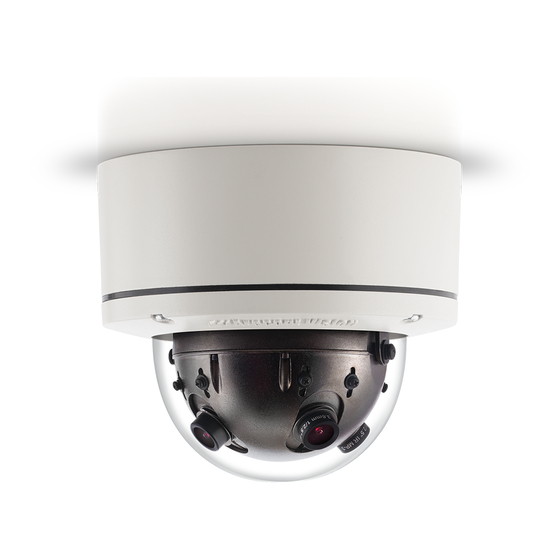
Page 6: Camera Overview
3/5 Megapixel sensors IK-10 vandal resistant dome and housing, rated IP66 for water and dust protection, to use camera for indoor and outdoor applications. ® G5 Mini Series is built with Arecont Vision’s proprietary massively-parallel The SurroundVideo ® ®... -
Page 7: Installation
® SurroundVideo G5 Mini Installation Manual Installation 1. Determine a secure location to mount the camera. 2. Use the supplied security L-key, to loosen the four (4) screws securing the dome cover. 3. Remove the dome cover and protective foam. Do not remove screws from the dome cover. ®... - Page 8 ® SurroundVideo G5 Mini Installation Manual Ensure you have the proper compatible mounting parts prior to starting your installation: Pendant mount Reference # Pendant Mount Components Required Pendant mount (AV-PMJB) with integrated junction box ® SurroundVideo G5 Mini camera MD-CAP mounting cap Wall mount Reference # Wall Mount Components Required...
- Page 9 G5 Mini camera AV-CRMA corner mount adapter 4. Use the Arecont Vision software AV IP Utility located on the CD or available for download at our website (www.arecontvision.com) for camera discovery and setup (see Instruction Manual located on the CD or available on our website).
-
Page 10: Surface Mount
® SurroundVideo G5 Mini Installation Manual Surface Mount ® The SurroundVideo G5 Mini camera can be directly attached onto hard ceilings or walls including wood, plastic, metal and concrete. 1. Use the template, anchors, and screws provided to prepare the mounting provisions for the camera installation. - Page 11 ® SurroundVideo G5 Mini Installation Manual 6. Prepare the network cable with the supplied grommet and insertion tool as shown in Figure 3. Figure 3 NOTE: When mounting the camera outdoors or in a wet environment, use of supplied grommet is recommended.
- Page 12 ® SurroundVideo G5 Mini Installation Manual 8. Fasten securely four captive screws as shown in Figure 5. Figure 5 ® 9. Attach the Dome Cover to the SurroundVideo G5 Mini camera and fasten securely four captive screws. 10. To configure the camera, reference the camera discovery, set-up and configuration section. CAUTION! The captive screws must be used to properly secure the dome cover and camera housing.
-
Page 13: Wall Mount
® SurroundVideo G5 Mini Installation Manual Wall Mount For a proper wall mount installation, the AV-WMJB wall mount and MD-CAP wall mount cap are required (sold separately). A wall mount should only be attached onto hard ceilings including wood, plastic, metal, and concrete. 1. - Page 14 ® SurroundVideo G5 Mini Installation Manual 6. Prepare the network cable with the supplied grommet and insertion tool as shown in Figure 3. Figure 3 NOTE: When mounting the camera outdoors or in a wet environment, use of supplied grommet is recommended.
- Page 15 ® SurroundVideo G5 Mini Installation Manual ® 9. Attach the Dome Cover to the SurroundVideo G5 Mini camera and fasten securely four captive screws as shown in Figure 6. Figure 6 10. To configure the camera, reference the camera discovery, set-up and configuration section. CAUTION! The captive screws must be used to properly secure the dome cover and camera housing.
-
Page 16: Pendant Mount
® SurroundVideo G5 Mini Installation Manual Pendant Mount For a proper pendant mount installation, the AV-PMJB pendant mount and MD-CAP mounting cap are required (sold separately). A pendant mount should only be attached onto hard ceilings including wood, plastic, metal, and concrete. 1. - Page 17 ® SurroundVideo G5 Mini Installation Manual 6. Prepare the network cable with the supplied grommet and insertion tool as shown in Figure 3. Figure 3 NOTE: When mounting the camera outdoors or in a wet environment, use of supplied grommet is recommended.
- Page 18 ® SurroundVideo G5 Mini Installation Manual ® 9. Attach the Dome Cover to the SurroundVideo G5 Mini camera and fasten securely four captive screws as shown in Figure 6. Figure 6 10. To configure the camera, reference the camera discovery, set-up and configuration section. CAUTION! The captive screws must be used to properly secure the dome cover and camera housing.
-
Page 19: Pole Mount
® SurroundVideo G5 Mini Installation Manual Pole Mount For a pole mount installation, the AV-WMJB wall mount, AV-PMA pole mount, and MD-CAP mount cap are required (sold separately). A pole mount should only be attached onto hard ceilings including wood, plastic, metal, and concrete. 1. - Page 20 ® SurroundVideo G5 Mini Installation Manual Figure 2: Attach wall mount adapter to pole mount adapter Reference # Description Steel straps with compression screws AV-WMJB wall mount MD-CAP mount cap Conduit AV-PMA pole mount Apply Teflon water seal tape to the thread of ¾” NPT pipe to avoid water leakage 7.
-
Page 21: Corner Mount
® SurroundVideo G5 Mini Installation Manual Corner Mount For a corner mount installation, the AV-WMJB wall mount, AV-CRMA corner mount, and MD- CAP mount cap are required (sold separately). A corner mount should only be attached onto hard corner surfaces including wood, plastic, metal, and concrete. 1. - Page 22 ® SurroundVideo G5 Mini Installation Manual Figure 2: Attach corner mount adapter to exterior corner wall Reference # Description Attach corner mount adapter to exterior 90 corner wall AV-WMJB wall mount MD-CAP mount cap Conduit AV-CRMA corner mount adapter Apply Teflon water seal tape to the thread of ¾” NPT pipe to avoid water leakage 7.
-
Page 23: Electrical Box Adapter
® SurroundVideo G5 Mini Installation Manual Electrical Box Adapter The mounting plate is used to attach the camera to a common single, double or square electrical box. 1. Using the supplied machine screws, match the mounting holes on the mounting plate with the threaded holes on the electrical box. -
Page 24: Mounting Recommendations
Installation Manual Mounting Recommendations For the best visibility toward the target, and a minimal blind spot below the camera, Arecont Vision recommends mounting panoramic cameras 15-20ft off the ground. If the application is unable to meet this criteria, for every 10ft the camera is mounted from the ground, expect a 10ft blind spot below, and the camera should be aimed ~100ft, for every 10ft mounted from the ground, toward the horizon. - Page 25 ® SurroundVideo G5 Mini Installation Manual In the example below, the camera in Figures 1D and 1E are both mounted 8ft high; however, the camera in Figure 1D is aimed 80ft toward the horizon and the camera in Figure 1E is only aimed at 30ft toward horizon.
-
Page 26: Adjusting The Pan, Tilt And Focus
® SurroundVideo G5 Mini Installation Manual Adjusting the Pan, Tilt and Focus 1. Remove the dome cover by loosening the captive fasteners with the supplied security L-key screwdriver. 2. Power on the camera to adjust the pan, tilt and focus. 3. - Page 27 ® SurroundVideo G5 Mini Installation Manual 5. To focus each of the four lenses, remove the lens cap and focus the lens by turning the lens clockwise or counterclockwise as shown in the image below: 180 Configuration 360 Configuration NOTE: The wave washer underneath the lens prevents it from losing focus in vibration. 1.
- Page 28 ® SurroundVideo G5 Mini Installation Manual Figure 1 To use digital I/O, connect digital I/O with pigtail cable connector as shown below. NOTE: SurroundVideo® G5 Mini suppots digital input and digital output. See Table 1 for electrical characteristics. Page | 28 support@arecontvision.com +1.818.937.0700 877.CAMERA.8...
- Page 29 ® SurroundVideo G5 Mini Installation Manual NOTE: The digital input is electrically isolated from the rest of the camera’s electrical circuity via general-purpose photo couplers. The input is additionally protected with a serial 250 Ohm resistor, and a de-bouncing circuit. Duration of any input signal should be at least 5 ms to comply with the requirements of the de-bouncing circuit.
-
Page 30: Camera Power Up
® SurroundVideo G5 Mini Installation Manual Camera Power Up This product should be installed by a qualified service technician in accordance with the National Electrical Code (NEC 800 CEC Section 60) or applicable local code. Make sure that your installation of wires complies with Electrical Code of the local government where the camera is installed and no bare wires are exposed. - Page 31 ® SurroundVideo G5 Mini Installation Manual Auxiliary Power If the camera is powered by a separate outside AC or DC power source, run the supplied power cable through the access hole on the camera housing and connect the power cable to the 4- position connector on the main camera board.
-
Page 32: Reset To Factory Default
Click on “Restore To Factory Default” as seen in Figure 2 Figure 2 ® NOTE: Additional information regarding the Arecont Vision web interface is found separately in the AV IP Utility Web Browser Manual via the Arecont Vision website. Page | 32 support@arecontvision.com +1.818.937.0700 877.CAMERA.8 www.arecontvision.com... -
Page 33: Camera Discovery, Setup And Configuration
AV IP Utility tool is efficient and convenient for mass or single camera uploads. The AV IP Utility tool is compatible with all Arecont Vision® megapixel cameras. The user manual for the software is included on the CD that came with your camera or available on our website. -
Page 34: Network Protocols
A QoS-aware network prioritizes network traffic and provides a greater network reliability by controlling the amount of bandwidth an application may use. IPv4 – The SurroundVideo G5 Mini supports the IPv4 internet-layer protocol for packet-switched internetworking across multiple IP networks. IPv4 uses 32-bit addressing which allows for devices and users on the internet for routing traffic. -
Page 35: Image Equalization (Exposure Reference) Instructions
® SurroundVideo G5 Mini Installation Manual Image Equalization (Exposure Reference) Instructions 1. Launch the camera webpage 2. If the camera is a SurroundVideo G5 NON-WDR, skip to step 3 on the next page. For a surroundVideo G5 WDR, Click “Setting” and select the desired channel to be the cameras “Exposure Reference Channel”... -
Page 36: Equalize Brightness Instructions
® SurroundVideo G5 Mini Installation Manual Exposure Reference Channel set as Channel “1” Exposure Reference Channel set as Channel “2” Equalize Brightness Instructions NOTE: For a SurroundVideo G5 NON-WDR camera, once the camera webpage is launched, you must make sure that “Equalize Brightness” function is on. You do this by : 3. - Page 37 ® SurroundVideo G5 Mini Installation Manual Image 6 *Please note the difference between the “Equalize Brightness” function “ON” and “OFF” in the images shown below: “Equalize Brightness” setting “OFF” “Equalize Brightness” setting “ON” Page | 37 support@arecontvision.com +1.818.937.0700 877.CAMERA.8 www.arecontvision.com avsales@arecontvision.com...
-
Page 38: Administration And Password Setting
NOTE: If the admin password has been set and forgotten, it can only be erased by AV IP Utility using key file. Please contact Arecont Vision technical support to obtain the key file required to perform this function. -
Page 39: Mounting Templates
® SurroundVideo G5 Mini Installation Manual Mounting Templates Unit: Inches Page | 39 support@arecontvision.com +1.818.937.0700 877.CAMERA.8 www.arecontvision.com avsales@arecontvision.com... -
Page 40: Support
3. Email: support@arecontvision.com 4. Use the Arecont Vision software AV IP Utility located on the CD or available for download at our website (www.arecontvision.com) for camera discovery and setup (see Instruction Manual located on the CD or available on our website).
Need help?
Do you have a question about the SurroundVideo G5 Mini and is the answer not in the manual?
Questions and answers