Table of Contents
Advertisement
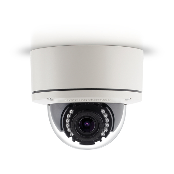
MegaDome
Installation Manual
Models
1.2 Megapixel
AV1355PM-S
AV1355PMIR-S
1080p
AV2355PMIR-SH
AV2356PMIR-S
AV2355PMIR-SAH
AV2355PMTIR-SH
AV2356PMTIR-S
3 Megapixel
AV3355PMIR-SH
AV3356PMIR-S
AV3356PMIR-SA
AV3355PMTIR-SH
AV3356PMTIR-S
®
G3
5 Megapixel
AV5355PMIR-SH
AV5355PMIR-SAH
AV5355PMTIR-SH
10 Megapixel
AV10355PMIR-SH
AV10355PMTIR-SH
Advertisement
Table of Contents

Related Manuals for Arecont Vision MegaDome G3


Summary of Contents for Arecont Vision MegaDome G3
- Page 1 ® MegaDome Installation Manual Models 1.2 Megapixel AV1355PM-S AV1355PMIR-S 1080p AV2355PMIR-SH AV2356PMIR-S 5 Megapixel AV2355PMIR-SAH AV5355PMIR-SH AV2355PMTIR-SH AV5355PMIR-SAH AV2356PMTIR-S AV5355PMTIR-SH 3 Megapixel 10 Megapixel AV3355PMIR-SH AV10355PMIR-SH AV3356PMIR-S AV10355PMTIR-SH AV3356PMIR-SA AV3355PMTIR-SH AV3356PMTIR-S...
-
Page 2: Table Of Contents
® MegaDome Installation Manual Contents Package Contents ............................ 3 Camera Overview ............................. 6 Installation ..............................7 Surface Mount ............................. 10 Wall Mount ............................13 Pendant Mount ........................... 16 Pole Mount ............................19 Corner Mount ............................21 Electrical Box Adapter ........................23 Adjusting the Pan, Tilt and Focus ...................... -
Page 3: Package Contents
® MegaDome Installation Manual CAUTION! 1. Do not attempt to service a damaged unit yourself. Refer all servicing to qualified service personnel. 2. Wiring methods shall be in accordance with the National Electrical Code/NFPA 70/ANSI, and with all local codes and authorities having jurisdiction. Wiring should be UL Listed and/or Recognized wire suitable for the application. - Page 4 ® MegaDome Installation Manual Reference # Description ® 1x Arecont Vision MegaDome G3 camera 1x Dome Cover 1x Mounting Plate 1x Grommet with Through Hole 1x Grommet without Through Hole 1x Insertion Tool 4x #6-32 1.0” Wood/ Metal Sheet Screw 4x #6-32 1.0”...
-
Page 5: Warranty Information
VISION’s written authorization; (ii) has not been used in accordance with applicable documentation; (iii) has been subjected to unusual stress, neglect, misuse, abuse, improper storage, testing or connection; or unauthorized repair; or (iv) is no longer covered under the Warranty Period. ARECONT VISION MAKE NO WARRANTIES OR CONDITIONS, EXPRESS, IMPLIED, STATUTORY OR OTHERWISE,... -
Page 6: Camera Overview
P-iris wide angle or telephoto varifocal lens, remote focus and remote zoom make MegaDome G3 easy to install and manage. The installer-friendly housing is IP66 environmental rated and IK-10 impact-resistant. MegaDome G3 is feature-loaded, and select models include STELLAR™... -
Page 7: Installation
® MegaDome Installation Manual Installation 1. Determine a secure location to mount the camera. 2. Use the supplied security L-key, to loosen the four (4) screws securing the dome cover. 3. Remove the dome cover and protective foam. Do not remove screws from the dome cover. ®... - Page 8 ® MegaDome Installation Manual Ensure you have the proper compatible mounting parts prior to starting your installation: Pendant mount Reference # Pendant Mount Components Required Pendant mount (AV-PMJB) with integrated junction box ® MegaDome G3 camera MD-CAP mounting cap Wall mount Reference # Wall Mount Components Required...
- Page 9 G3 camera AV-CRMA corner mount adapter 4. Use the Arecont Vision software AV IP Utility located on the CD or available for download at our website (www.arecontvision.com) for camera discovery and setup (see Instruction Manual located on the CD or available on our website).
-
Page 10: Surface Mount
® MegaDome Installation Manual Surface Mount ® The MegaDome G3 camera can be directly attached onto hard ceilings or walls including wood, plastic, metal and concrete. 1. Use the template, anchors, and screws provided to prepare the mounting provisions for the camera installation. - Page 11 ® MegaDome Installation Manual 6. Prepare the network cable with the supplied grommet and insertion tool as shown in Figure 3. Figure 3 NOTE: When mounting the camera outdoors or in a wet environment, use of supplied grommet is recommended. Ensure the grommet is properly seated flush with the camera housing. ®...
- Page 12 ® MegaDome Installation Manual 8. Fasten securely four captive screws as shown in Figure 5. Figure 5 ® 9. Attach the Dome Cover to the MegaDome G3 camera and fasten securely four captive screws. NOTE: When attaching the Dome Cover, make sure the IR foam on the lens not block the field of view.
-
Page 13: Wall Mount
® MegaDome Installation Manual Wall Mount For a proper wall mount installation, the AV-WMJB wall mount and MD-CAP wall mount cap are required (sold separately). A wall mount should only be attached onto hard ceilings including wood, plastic, metal, and concrete. 1. - Page 14 ® MegaDome Installation Manual 6. Prepare the network cable with the supplied grommet and insertion tool as shown in Figure 3. Figure 3 NOTE: When mounting the camera outdoors or in a wet environment, use of supplied grommet is recommended. Ensure the grommet is properly seated flush with the camera housing. ®...
- Page 15 ® MegaDome Installation Manual ® 9. Attach the Dome Cover to the MegaDome G3 camera and fasten securely four captive screws as shown in Figure 6. Figure 6 NOTE: When attaching the Dome Cover, make sure the IR foam on the lens not block the field of view.
-
Page 16: Pendant Mount
® MegaDome Installation Manual Pendant Mount For a proper pendant mount installation, the AV-PMJB pendant mount and MD-CAP mounting cap are required (sold separately). A pendant mount should only be attached onto hard ceilings including wood, plastic, metal, and concrete. 1. - Page 17 ® MegaDome Installation Manual 6. Prepare the network cable with the supplied grommet and insertion tool as shown in Figure 3. Figure 3 NOTE: When mounting the camera outdoors or in a wet environment, use of supplied grommet is recommended. Ensure the grommet is properly seated flush with the camera housing. ®...
- Page 18 ® MegaDome Installation Manual ® 9. Attach the Dome Cover to the MegaDome G3 camera and fasten securely four captive screws as shown in Figure 6. Figure 6 NOTE: When attaching the Dome Cover, make sure the IR foam on the lens not block the field of view.
-
Page 19: Pole Mount
® MegaDome Installation Manual Pole Mount For a pole mount installation, the AV-WMJB wall mount, AV-PMA pole mount, and MD-CAP mount cap are required (sold separately). A pole mount should only be attached onto hard ceilings including wood, plastic, metal, and concrete. 1. - Page 20 ® MegaDome Installation Manual Figure 2: Attach wall mount adapter to pole mount adapter Reference # Description Steel straps with compression screws AV-WMJB wall mount MD-CAP mount cap Conduit AV-PMA pole mount Apply Teflon water seal tape to the thread of ¾” NPT pipe to avoid water leakage 7.
-
Page 21: Corner Mount
® MegaDome Installation Manual Corner Mount For a corner mount installation, the AV-WMJB wall mount, AV-CRMA corner mount, and MD- CAP mount cap are required (sold separately). A corner mount should only be attached onto hard corner surfaces including wood, plastic, metal, and concrete. 1. - Page 22 ® MegaDome Installation Manual Figure 2: Attach corner mount adapter to exterior corner wall Reference # Description Attach corner mount adapter to exterior 90 corner wall AV-WMJB wall mount MD-CAP mount cap Conduit AV-CRMA corner mount adapter Apply Teflon water seal tape to the thread of ¾” NPT pipe to avoid water leakage 7.
-
Page 23: Electrical Box Adapter
® MegaDome Installation Manual Electrical Box Adapter The mounting plate is used to attach the camera to a common single, double or square electrical box. 1. Using the supplied machine screws, match the mounting holes on the mounting plate with the threaded holes on the electrical box. -
Page 24: Adjusting The Pan, Tilt And Focus
® MegaDome Installation Manual Adjusting the Pan, Tilt and Focus 1. Remove the dome cover by loosening the captive fasteners with the supplied security L-key screwdriver. 2. Power on the camera to adjust the pan, tilt and focus. 3. Remove the shroud from the camera gimbal, and then loose two Philips head screws and loose one set-screw with the supplied set screw L-key, and then adjust the pan and tilt to obtain the desired field of view as shown in Figure 1. - Page 25 ® MegaDome Installation Manual NOTE: Make sure align locking features of the shroud with mating parts on the camera gimbal shown in Figure Figure 3 6. To adjust the zoom and focus, see the Remote Zoom/ Focus Section of this manual. Page | 25 support@arecontvision.com +1.818.937.0700...
-
Page 26: Auxiliary I/O Functions
® MegaDome Installation Manual Auxiliary I/O Functions The auxiliary input and output are accessible after removing dome cover. Reference # Description Input (White + / Black -) Output (Orange + / Yellow -) ® NOTE: MegaDome G3 camera supports digital input and digital output. See Table 1 for electrical characteristics. - Page 27 ® MegaDome Installation Manual Digital I/O Orange Digital OUT + Yellow Digital OUT - White Digital IN + Black Digital IN - Table 2 Page | 27 support@arecontvision.com +1.818.937.0700 877.CAMERA.8 www.arecontvision.com avsales@arecontvision.com...
-
Page 28: Camera Power Up
® MegaDome Installation Manual Camera Power Up This product should be installed by a qualified service technician in accordance with the National Electrical Code (NEC 800 CEC Section 60) or applicable local code. 1. Connect the camera to a PoE port on 100Mbps network PoE switch using an Ethernet cable as shown in the image below. - Page 29 ® MegaDome Installation Manual NOTE: Cameras using auxiliary power with 802.1x enabled may need to manually power cycle the camera to reconnect to the network. CAUTION! Make the connections inside a watertight compartment. Isolate unused power wires individually. After connections are made, ensure that the watertight compartment is tightly closed and cables and conduits are properly sealed to prevent ingress of water.
-
Page 30: Sd Card Set-Up
The camera supports class 10 microSD or microSDHC cards up to 32GB. Not all SD cards are the same. Arecont Vision highly recommends using SanDisk Extreme Micro SD cards (or an equivalent substitute) as these cards have been fully tested without issue. The SanDisk Extreme line is better suited for demanding applications like constant recording. - Page 31 ® MegaDome Installation Manual SD Card Set-up via Web Interface To set-up the SD card via the web interface, open your preferred web browser and type the camera’s IP address. NOTE: For supporting H.264 streaming on a webpage, the recommended browsers are Internet Explorer and Firefox.
- Page 32 • Playback tips: Video recorded to an SD card from an Arecont Vision camera can only be played back via an Arecont Vision camera that has the same or lower resolution. Playback cannot be viewed with any other device. For example, video recorded to an SD card via a 10MP camera can be played back on a 3MP camera but a 3MP cannot be played back on a 10MP model.
-
Page 33: Sd Card Tab
® MegaDome Installation Manual SD Card Tab Menu Feature Description View SD Recording drag the box to the area where need Allows the user to to be recorded. Continuous Recording Allows the user to continuously record without restriction. Default is unchecked box. Stop Continuous Allows the user to enable events recording when network Recording AND Enable... -
Page 34: Sd Card Setup Via Av200
® MegaDome Installation Manual SD Card Setup via AV200 To set-up the SD card via AV200, launch the AV200 application icon on the desktop. To enable recording to the SD card, select the desired camera and drag it to the workspace to open a view. -
Page 35: Camera Discovery, Setup, And Configuration
AV IP Utility tool is efficient and convenient for mass or single camera uploads. The AV IP Utility tool is compatible with all Arecont Vision® megapixel cameras. The user manual for the software is included on the CD that came with your camera or available on our website. -
Page 36: General Remote Focus
Figure 1: Double click via AV IP Utility Figure 2: Type the camera IP address 2. Click Focus Tab ® NOTE: Additional information regarding the Arecont Vision web interface is found separately in the AV IP Utility Web Browser Manual via the Arecont Vision website. -
Page 37: Refined Remote Focus
® MegaDome Installation Manual Refined Remote Focus 1. For a more refined, detailed focus For a more refined, detailed focus, scroll to the Video Tab section and select the Enable Digital Zoom Control radial button. 2. Choose an area that has a lot of objects or an area you have an interest in seeing more details. Left click and drag the box to the area where you want to see finer details. - Page 38 ® MegaDome Installation Manual 4. Scroll to the Focus Tab section and enable the View Focus Window. 5. Left click and drag to highlight the area within the zoomed window you created. 6. Click Short-range Focus button. 7. The camera proceeds to go through the short range adjustment around the original focus. It stops at the best point of focus using the new reference area.
-
Page 39: Av Ip Utility Focus Tab
® MegaDome Installation Manual AV IP Utility Focus Tab Menu Feature Description View Focus Window Allows the user to drag the box to the area where need to be focused on. Manual Zoom/ Focus: Numbers indicate the level of Zooming/ focusing in order to +20, +5, +1, -20, -5, -1 adjust the field-of-view. -
Page 40: Mounting Templates
® MegaDome Installation Manual Mounting Templates Unit: Inches Page | 40 support@arecontvision.com +1.818.937.0700 877.CAMERA.8 www.arecontvision.com avsales@arecontvision.com... -
Page 41: Support
3. Email: support@arecontvision.com 4. Use the Arecont Vision software AV IP Utility located on the CD or available for download at our website (www.arecontvision.com) for camera discovery and setup (see Instruction Manual located on the CD or available on our website).
Need help?
Do you have a question about the MegaDome G3 and is the answer not in the manual?
Questions and answers