
Related Manuals for Arecont Vision AV12275DN-NL


Summary of Contents for Arecont Vision AV12275DN-NL
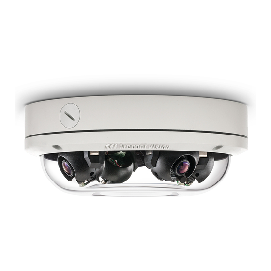
- Page 1 SurroundVideo® O mni G 2 Installation Manual Models: 12 Megapixel • AV12275DN-NL • AV12275DN-28 • AV12275DN-08 • AV12276DN-NL • AV12276DN-28 • AV12276DN-08 20 Megapixel • AV20275DN-NL • AV20275DN-28 • AV20275DN-08 ...
-
Page 2: Table Of Contents
SurroundVideo® O mni G 2 Installation M anual Contents Package Contents .............................. 3 In-ceiling Mount .............................. 1 0 Pendant Mount .............................. 1 2 ... -
Page 3: Package Contents
This equipment should be unpacked and handled with care. The original packaging is the safest container in which to transport the unit and can be used if returning the unit for service. The packaging contains: One (1) Arecont Vision Camera • One (1) mounting template •... -
Page 4: Warranty Information
VISION’s written authorization; (ii) has not been used in accordance with applicable documentation; (iii) has been subjected to unusual stress, neglect, misuse, abuse, improper storage, testing or connection; or unauthorized repair; or (iv) is no longer covered under the Warranty Period. ARECONT VISION MAKE NO WARRANTIES OR CONDITIONS, EXPRESS, IMPLIED, STATUTORY OR OTHERWISE,... -
Page 5: Camera Overview
SurroundVideo® O mni G 2 Installation M anual Camera Overview The SurroundVideo® Omni G2, next generation multi-sensor, multi-megapixel dome camera pushes the ease of installation even further providing users with four (4) remote focus lens options on a unique 360°... - Page 6 SurroundVideo® O mni G 2 Installation M anual Installation 1. Determine a secure location to mount the camera. 2. Use the supplied security L-key, to loosen the four (4) screws securing the dome cover. 3.
- Page 7 SurroundVideo® O mni G 2 Installation M anual Ensure you have the proper compatible mounting parts prior to starting your installation: Pendant mount Reference # Pendant Mount Components Required Pendant mount (AV-PMJB) with integrated junction box SurroundVideo®...
- Page 8 SurroundVideo® O mni G 2 Installation M anual Pole mount Reference # Mount Type Pole Mount Components Required AV-WMJB wall mount SO-CAP mount cap Pole mount SurroundVideo® Omni G2 camera AV-PMA pole mount adapter ...
- Page 9 NOTE: It is recommended to conduct periodic inspections of the installation. Rust on the metal parts or screws may result in damage to the camera. 4. Use the Arecont Vision software AV IP Utility located on the CD or available for download at our website (www.arecontvision.com) for camera discovery and setup (see Instruction Manual located on the CD or available on our website).
-
Page 10: In-Ceiling Mount
SurroundVideo® O mni G 2 Installation M anual In-ceiling Mount To properly flush mount the SurroundVideo® Omni G2 to a drop ceiling or similar surface, a flush mount adapter kit (SO-FMA) is required (sold separately). 1. - Page 11 SurroundVideo® O mni G 2 Installation M anual Figure 3: Compress the mounting surface with lever screws Reference # Description SO-FMA flange plate support arm Lever screw SurroundVideo Omni G2 camera Rubber gasket Dome cover SO-FMA trim ring...
-
Page 12: Pendant Mount
SurroundVideo® O mni G 2 Installation M anual Pendant Mount For a proper pendant mount installation, the AV-PMJB pendant mount and SO-CAP mount cap are required (sold separately). A pendant mount should only be attached onto hard ceilings including wood, plastic, metal, and concrete. -
Page 13: Surface Mount
SurroundVideo® O mni G 2 Installation M anual Surface Mount The SurroundVideo® Omni G2 can be directly attached onto hard ceilings or walls including wood, plastic, metal and concrete. 1. Use the template, anchors, and screws provided to prepare the mounting provisions for the camera installation. - Page 14 SurroundVideo® O mni G 2 Installation M anual 3. Remove the dome cover and set aside. Remove the protective foam and discard. 4. If mounting the camera outside or in a wet environment, thread the camera cable through the hole on the supplied rubber gasket and align with the three holes on the top of the housing.
- Page 15 SurroundVideo® O mni G 2 Installation M anual Reference # Description Install 3 supplied dry wall anchors using the supplied mounting template Attach supplied (optional) tether plate Attach supplied rubber gasket to the camera housing by threading the camera cable through the hole in the gasket (ensure the gasket is seated properly) Align 3 supplied screws with the dry wall anchors and screw camera into place Attach the dome cover, ensuring the rubber gasket is properly seated, with the...
-
Page 16: Wall Mount
SurroundVideo® O mni G 2 Installation M anual Wall Mount For a proper wall mount installation, the AV-WMJB wall mount and SO-CAP wall mount cap are required (sold separately). A wall mount should only be attached onto hard ceilings including wood, plastic, metal, and concrete. -
Page 17: Pole Mount
SurroundVideo® O mni G 2 Installation M anual Pole Mount For a pole mount installation, the AV-WMJB wall mount, AV-PMA pole mount, and SO-CAP mount cap are required (sold separately). A pole mount should only be attached onto hard ceilings including wood, plastic, metal, and concrete. - Page 18 SurroundVideo® O mni G 2 Installation M anual Figure 2: Attach wall mount adapter to pole mount adapter Reference # Description Steel straps with compression screws AV-WMJB wall mount SO-CAP mount cap Conduit AV-PMA pole mount AV-JBA Junction box...
-
Page 19: Corner Mount
SurroundVideo® O mni G 2 Installation M anual Corner Mount For a corner mount installation, the AV-WMJB wall mount, AV-CRMA corner mount, and SO-CAP mount cap are required (sold separately). A corner mount should only be attached onto hard corner surfaces including wood, plastic, metal, and concrete. - Page 20 SurroundVideo® O mni G 2 Installation M anual Figure 2: Attach corner mount adapter to exterior corner wall Reference # Description Attach corner mount adapter to exterior 90° corner wall AV-WMJB wall mount SO-CAP mount cap Conduit AV-CRMA corner mount adapter...
-
Page 21: Electrical Box Adapter
SurroundVideo® O mni G 2 Installation M anual Electrical Box Adapter The AV-EBA electrical box adapter is used to attach the camera to a common single, double or square electrical box. 1. Using the AV-EBA’s supplied machine screws, match the mounting holes on the adapter with the threaded holes on the electrical box. -
Page 22: Setting Up The Cameras
SurroundVideo® O mni G 2 Installation M anual Setting up the Cameras The SurroundVideo® Omni is user configurable. Prior to installing the camera, thought should be given to the sensor positions. It is always easier to make adjustments before the camera is installed. The camera lenses are shipped in a 360º... - Page 23 SurroundVideo® O mni G 2 Installation M anual Reference # Description 180° configuration Random configuration 270º configuration Assembly line configuration Random configuration Page | 23 support@arecontvision.com +1.818.937.0700 877.CAMERA.8 www.arecontvision.com avsales@arecontvision.com...
-
Page 24: Aligning The Cameras
SurroundVideo® O mni G 2 Installation M anual Aligning the Cameras Properly aligning each camera is essential during setup. Each camera must be placed in a counterclockwise sequence on the circumference of the track to ensure proper viewing of each camera. ... -
Page 25: Adjusting The Pan, Tilt And Focus
SurroundVideo® O mni G 2 Installation M anual Adjusting the Pan, Tilt and Focus 1. Remove the dome cover by loosening the captive fasteners with the supplied Philips head screwdriver. 2. Power on the camera to adjust the pan, tilt and focus. 3. -
Page 26: Changing The Lens
SurroundVideo® O mni G 2 Installation M anual NOTE: Positioning the lens motor to close to the board may cause interference with the magnetic Omni track. Ensure each lens motor is positioned away from the board. Incorrect Correct Changing the Lens... -
Page 27: Optional: Connecting Digital I
SurroundVideo® O mni G 2 Installation M anual Optional: Connecting Digital I/O To use digital I/O, connect digital I/O with pigtail cable connector as shown below. Reference # Description Input (White + / Black -) Output (Orange + / Yellow -) NOTE: SurroundVideo®... - Page 28 SurroundVideo® O mni G 2 Installation M anual Digital I/O Orange Digital OUT + Yellow Digital OUT - White Digital IN + Black Digital IN - Table 2 The 4 position connector inside camera housing located on the main circuit board used for I/O can be accessed by removing the track plate.
-
Page 29: Auxiliary I/O Functions
SurroundVideo® O mni G 2 Installation M anual Auxiliary I/O Functions The auxiliary input and output are accessible from the back panel, as shown in Figure 1. OUT+ OUT-‐ IN-‐ Figure 1 The output consists of an optically coupled solid state relay (SSR) and the input has an optocoupler. -
Page 30: Output Relay Control And Function
SurroundVideo® O mni G 2 Installation M anual OUTPUT Relay Control and Function The camera has an output for activating an external device. The camera supports both transient and continuous relay operation. You can operate the relay during an active connection using the API command set. -
Page 31: Input Alarm Control And Detection
Installation M anual INPUT Alarm Control and Detection The input optocoupler supports two ways to connect external unsupervised alarms to Arecont Vision camera. Only one of the following two schemes should be used at any given time. OPTION-1: UNSUPERVISED ALARM D ETECTION In this scheme the IN+ &... - Page 32 SurroundVideo® O mni G 2 Installation M anual OPTION-2: INPUT VOLTAGE D ETECTION In this scheme the IN- & GND terminals can be tied to an external power source. The camera can detect a range of voltage to trigger an internal alarm on|off condition.
-
Page 33: Auxiliary Power
SurroundVideo® O mni G 2 Installation M anual Camera Power Up This product should be installed by a qualified service technician in accordance with the National Electrical Code (NEC 800 CEC Section 60) or applicable local code. Make sure that your installation of wires complies with Electrical Code of the local government where the camera is installed and no bare wires are exposed. - Page 34 SurroundVideo® O mni G 2 Installation M anual CAUTION! Make the connections inside a watertight compartment. Isolate unused power wires individually. After connections are made, ensure that the watertight compartment is tightly closed and cables and conduits are properly sealed to prevent ingress of water.
-
Page 35: Camera Discovery, Setup, And Configuration
AV IP Utility tool is efficient and convenient for mass or single camera uploads. The AV IP Utility tool is compatible with all Arecont Vision® megapixel cameras. The user manual for the software is included on the CD that came with your camera or available on our website. -
Page 36: General Remote Focus
2. Scroll to the Focus Tab section. ® NOTE: Additional information regarding the Arecont Vision web interface is found separately in the A V IP Utility Web Browser Manual v ia the Arecont Vision website. Page | 36 support@arecontvision.com ... -
Page 37: Refined Remote Focus
SurroundVideo® O mni G 2 Installation M anual 3. Click the Full-range Focus button. The camera begins to autofocus with the lens stopping at the best overall point of focus. When the focus area turns to Green, the autofocus is complete. ... - Page 38 SurroundVideo® O mni G 2 Installation M anual 4. Select the radial Focus Window option. ...
-
Page 39: Av Ip Utility Focus Tab
SurroundVideo® O mni G 2 Installation M anual AV IP Utility Focus Tab Menu Feature Description Manual Focus: Numbers indicate the level of focusing in order to adjust the field-of-view. +20, +5, +1, - 20, -5, -1 To set-up a focus area (if necessary), draw a rectangle with the mouse (by left-clicking and dragging the mouse to a desired zoom size). -
Page 40: Troubleshooting
SurroundVideo® O mni G 2 Installation M anual Troubleshooting Before troubleshooting, visit http://www.arecontvision.com/ to ensure your camera has the most current firmware version. Problem Possible Cause Solution Lens faces the bubble’s Ensure the lens faces the bubble •... -
Page 41: Surroundvideo Omni Mounting Template
SurroundVideo® O mni G 2 Installation M anual SurroundVideo Omni Mounting Template Page | 41 support@arecontvision.com +1.818.937.0700 877.CAMERA.8 www.arecontvision.com avsales@arecontvision.com... -
Page 42: Support
Swap the “troubled” camera with a known good camera to see if the problem follows the • camera or stays at the location. 3. Contact Arecont Vision Technical Support one of three ways: 1. Online Portal: Support.ArecontVision.com 2. Phone: 1.818.937.0700 (option #1) 3.
Need help?
Do you have a question about the AV12275DN-NL and is the answer not in the manual?
Questions and answers