Table of Contents

Subscribe to Our Youtube Channel
Related Manuals for Intel R2600SR Series


Summary of Contents for Intel R2600SR Series
- Page 1 Intel® Server System R2600SR Product Family Setup and Service Guide A guide providing initial setup instructions and procedures to insert and extract system components. Rev 1.1 March 2018 Intel® Server Products and Solutions...
- Page 2 <Blank page>...
- Page 3 Intel® Server System R2600SR Setup and Service Guide Document Revision History Date Revision Changes February 2018 Initial release. Added replacement instructions for the PCIe* I/O Risers and for the Power Distribution March 2018 Module.
- Page 4 Learn more at Intel.com, or from the OEM or retailer. You may not use or facilitate the use of this document in connection with any infringement or other legal analysis concerning Intel products described herein. You agree to grant Intel a non-exclusive, royalty-free license to any patent claim thereafter drafted which includes subject matter disclosed herein.
- Page 5 Servergehäusen unter http://support.intel.com/support/motherboards/server/sb/cs-010770.htm. Consignes de sécurité Lisez attention toutes les consignes de sécurité et les mises en garde indiquées dans ce document avant de suivre toute instruction. Consultez Intel Server Boards and Server Chassis Safety Information sur le site http://support.intel.com/support/motherboards/server/sb/cs- 010770.htm.
- Page 6 Intel recommends the following steps be taken when performing any procedures described within this document or while performing service to any computer system.
- Page 7 Intel® Server System R2600SR Setup and Service Guide Disconnect all power cables and cords attached to the server before performing any integration or • service Touch any unpainted metal surface of the chassis before performing any integration or service •...
-
Page 8: Table Of Contents
Intel® Server System R2600SR Setup and Service Guide Table of Contents 1. Introduction .................................. 7 The Intel ® Server System R2600SR Product Family ................... 7 About This Document ..............................7 Document Organization ..............................7 Resource Information and Software ......................... 8 2. - Page 9 Intel® Server System R2600SR Setup and Service Guide Replacing DIMMs ................................34 3.6.1 Preparing to Remove a DIMM ........................... 34 3.6.2 Removing a DIMM ................................35 3.6.3 Installing a DIMM ................................35 Replacing the Drive Carrier ............................36 3.7.1 Extracting the Drive Carrier ............................36 3.7.2...
- Page 10 Intel® Server System R2600SR Setup and Service Guide 3.15.4 Installing the System Shuttle ............................ 63 3.16 Replacing the PCIe* Add-in Card ..........................64 3.16.1 Preparing to Remove a PCIe* Add-in Card ......................64 3.16.2 Removing the PCIe* Add-in Card ..........................65 3.16.3...
- Page 11 Intel® Server System R2600SR Setup and Service Guide Figure 20. Removing a PHM .................................. 28 Figure 21. Separating the processor and carrier from the heat sink ................... 28 Figure 22. Separating the processor from the processor clip ....................29 Figure 23. Installing a processor onto a processor clip ......................30 Figure 24.
- Page 12 Intel® Server System R2600SR Setup and Service Guide Figure 61. Fan cable disconnection from the PIOR, left ......................68 Figure 62. Screw removal ..................................69 Figure 63. PIOR, left removal................................69 Figure 64. Fan cable disconnection from the PIOR, right ......................70 Figure 65.
-
Page 13: Introduction
About This Document This Intel® Server System R2600SR Product Family Setup and Service Guide is written for system integrators and service technicians responsible for system setup, server and system upgrades, and repair. -
Page 14: Resource Information And Software
Server System R2600SR Product Family Technical Product Specification Intel® Server System BIOS Setup Utility Guide In-depth technical information about Product Safety and Regulatory Compliance - Intel® Xeon® processor Scalable this product family Family System integration instructions and ... -
Page 15: System Overview And Setup
Intel® Server System R2600SR Setup and Service Guide System Overview and Setup This chapter provides service personnel the information necessary to set up the Intel® Server System R2600SR L9 system. Illustrations identify and locate the system features and procedures to install the system in a rack environment and configure the system, including updating and backing up firmware. -
Page 16: System Component Quick Reference
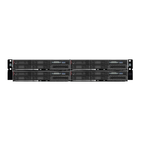
2.1.1 System Front View The Intel® Server System R2600SR product family system’s four compute nodes are removable from the front without power down to allow for high availability operation. The illustration shows the disposition of the compute nodes in the system as well as other features. -
Page 17: Compute Node View
Intel® Server System R2600SR Setup and Service Guide Figure 2. System back view 2.1.3 Compute Node View Each compute node offers local manageability through a front panel, Keyboard/Video/Mouse (KVM) Module, and USB 3.0 and 3.1 ports. It also supports a pullout tab for identification and/or network information. -
Page 18: Figure 4. Server Board Feature Identification
Intel® Server System R2600SR Setup and Service Guide 2.1.3.1 Server Board Feature Identification The illustration shows the main features of the server board. Figure 4. Server board feature identification 2.1.3.2 Server Board Switches The following illustration shows the location and description of the switches on the server board. -
Page 19: System Installation Into A Rack
The illustrations in this subsection display all items needed to install the system into a rack. These items are included with the system. Note: If any items are missing or damaged, contact Intel Customer Support. The slide box of the rack kit includes these parts: ... -
Page 20: Installing The Rail Kit
Intel® Server System R2600SR Setup and Service Guide These parts appear in the illustration below. Figure 6. Slide box contents 2.2.1 Installing the Rail Kit To install the rail kit, complete the steps below: Figure 7. Installing the rear rail Note: The holes on the front and rear of the rack may be either square or round. -
Page 21: Installing The System Onto The Rail Kit
Intel® Server System R2600SR Setup and Service Guide Figure 8. Installing the front rail 5. Pull the slide forward: insert the pins and the latch into the EIA flange holes at the front of the rack. 6. Repeat the process for the rail on the opposite side of the rack. -
Page 22: Sliding The System Chassis Into The Rack
Intel® Server System R2600SR Setup and Service Guide Figure 10. Installing the system chassis on the slide rails 4. Tilt and lower the system chassis; then, push the slides towards it and make sure the farthest nailheads go into the slots on the slides (see Number 1). -
Page 23: System Configuration And Management
A number of different tool options are available to install and configure firmware and manage the system. Brief descriptions of available tools are listed below. For more information, please see the Intel® Server System R2600SR Product Family System Management Module User's Guide. -
Page 24: Setting Up The System Management Module (Smm) Network Connection
Intel® Server System R2600SR Setup and Service Guide Complete the following steps to connect the BMC to the network: 1. Start the system. 2. When <F1> Setup appears, press F1. 3. Specify how the BMC will connect to the network. -
Page 25: Table 3. Individual Ipmi Command Code Details
Intel® Server System R2600SR Setup and Service Guide The table below references details of the individual codes within the IPMI commands listed above. Table 3. Individual IPMI command code details Net Function = 0x3A Code Command Request, Response Data Description Request: •... -
Page 26: System Firmware Update And Backup
The latest version of the system software stack can be downloaded at: http://downloadcenter.intel.com For information and action steps, please see the Intel® Server System R2600SR Product Family System Management Module User's Guide. 2.4.1... -
Page 27: System Service
Tools and Supplies Needed Before setting up, configuring, and backing up (integrating) the Intel® Server System R2600SR: 1. Observe the safety and ESD precautions found in the Warnings section in this manual. -
Page 28: Removing The Compute Node
Intel® Server System R2600SR Setup and Service Guide 3.1.1 Removing the Compute Node The compute node must be removed before servicing any component except the drive carrier and SSD in order to give access to that component. When removing a compute node, make note of the node bay number. Some configuration information and update options are established according to node bay number. -
Page 29: Installing The Compute Node
Intel® Server System R2600SR Setup and Service Guide 3.1.2 Installing the Compute Node Figure 13. Installing the compute node 1. Make sure that the locking lever on the compute node is turned all the way left. 2. Slide the compute node into the node bay until it stops. -
Page 30: Installing The Compute Node Cover
Intel® Server System R2600SR Setup and Service Guide 1. Remove the compute node from the system. (see Section 0) 2. Push the cover release latch on the top of the node cover. 3. Slide the cover toward the rear of the node until the cover has disengaged from the node, then lift the cover up and away from the node. -
Page 31: Replacing The Air Baffle
Intel® Server System R2600SR Setup and Service Guide Replacing the Air Baffle Always operate this server system with the air baffle in place. The air baffle is required for proper airflow within the server system. Figure 16. Removing the air baffle The air baffle is removed for access to the node DIMMs and midplane cables. -
Page 32: Replacing The Cmos Battery
Intel® Server System R2600SR Setup and Service Guide 1. Align the air baffle latches with the baffle slots on both sides of the chassis. 2. Lower the air baffle straight down into the node. Press the air baffle down until it is securely seated and the latches lock into place. -
Page 33: Replacing The Processor Heat Sink Module (Phm)
Intel® Server System R2600SR Setup and Service Guide Figure 19. Installing the CMOS battery 5. Follow any special handling and installation instructions that come with the replacement battery. 6. Position the battery next to the socket and tilt the battery so that it can inserted into the socket bottom first, positive side towards the outside edge of the board. -
Page 34: Separating The Processor And Processor Clip From The Heat Sink
Intel® Server System R2600SR Setup and Service Guide Figure 20. Removing a PHM 1. Fully loosen the Torx T30 captive fasteners on the PHM in the removal sequence shown on the heat sink label (see Numbers 1-4). 2. Lift the PHM straight up and away from the processor socket. -
Page 35: Separating The Processor From The Processor Clip
Intel® Server System R2600SR Setup and Service Guide 1. With the heat sink facing down, place the PHM onto a flat non-conductive surface. 2. Press the retaining clip at the corner of the processor clip (see Numbers 1, 3, 4 and 5) closest to the pry point (see Number 2) to release it. -
Page 36: Installing A Processor On The Processor Clip
Intel® Server System R2600SR Setup and Service Guide 3.4.4 Installing a Processor on the Processor Clip The processor must be installed onto a processor clip before it is installed as part of the PHM. Follow these steps to attach a processor clip to the processor. -
Page 37: Assembling The Processor Heat Sink Module (Phm)
Intel® Server System R2600SR Setup and Service Guide Note: Use only an appropriate TIM when replacing the processor such as: PCM45F (70x47x0.25) by Honeywell International, Inc., Honeywell P/N: 099079. This link provides a demonstration of the application of the TIM: https://www.intel.com/content/www/us/en/support/articles/000025195/processors/intel-xeon-... -
Page 38: Installing The Processor Heat Sink Module (Phm)
Intel® Server System R2600SR Setup and Service Guide 3.4.6 Installing the Processor Heat Sink Module (PHM) PHMs are keyed for the socket in which they can be installed and their orientation within that socket. Note: Before installing a new PHM or replacement processor, update the system firmware to the latest level. -
Page 39: Supporting And Populating The Memory Module (Dimm)
Intel® Server System R2600SR Setup and Service Guide Supporting and Populating the Memory Module (DIMM) The server board is capable of supporting 16 DIMMs (8 DIMMs per processor). However, to support the processors in this system with a TDP of 200W or 205W, larger CPU heat sinks are used to support the increased thermals of these processors. -
Page 40: Dimm Replacement Recommendations
Intel® Server System R2600SR Setup and Service Guide 3.5.3 DIMM Replacement Recommendations When installing and replacing DIMMs, follow the guidelines below: Install higher capacity (ranked) DIMMs first, following the population sequence for the memory mode being used. Do not mix RDIMMs, LRDIMMs and 3DS DIMMs in the same node. -
Page 41: Removing A Dimm
Intel® Server System R2600SR Setup and Service Guide 3.6.2 Removing a DIMM To remove a DIMM, complete the following steps: 1. Open the locking latches at either end of the selected DIMM connector (see Letter A). The DIMM will be unseated from the connector. -
Page 42: Replacing The Drive Carrier
Intel® Server System R2600SR Setup and Service Guide Replacing the Drive Carrier Each compute node within the system is pre-populated with an SSD installed in a drive carrier. The single SSD in its pre-populated drive bay is the only drive supported in this system. -
Page 43: Replacing The Drive Backplane
Intel® Server System R2600SR Setup and Service Guide Replacing the Drive Backplane The drive backplane is located in the compute node between the rear of the drive bays and the back edge of the server board. 3.8.1 Removing the Drive Backplane Note: The drive backplane actually in the system may differ from those shown below. -
Page 44: Installing The Drive Backplane
Intel® Server System R2600SR Setup and Service Guide Figure 32. Removing the drive backplane 5. Turn the two (2) latches to the release position (see Number 1) and lift the backplane to disengage and remove the backplane from the node by lifting straight up and out (see Number 2). -
Page 45: Replacing The Keyboard/Video/Mouse (Kvm) Module
Intel® Server System R2600SR Setup and Service Guide Replacing the Keyboard/Video/Mouse (KVM) Module Installed within the front panel of each compute node (Figure 1, top row, right) is a Keyboard/Video/Mouse (KVM) Module, which provides support for one USB 3.0 Port and one KVM Breakout Cable (1 per system). -
Page 46: Replacing The Kvm Module
Intel® Server System R2600SR Setup and Service Guide 3.9.2 Replacing the KVM Module Complete the following steps to install a KVM module: 1. Turn off the corresponding compute node with the KVM module to be removed. 2. Remove the compute node (see Section 3.2.1). -
Page 47: Figure 38. Kvm Cable Routing
Intel® Server System R2600SR Setup and Service Guide 3.9.2.1 Attaching the KVM Cable Figure 38. KVM cable routing Once the KVM module has been replaced, attach the KVM Breakout cable to attach the KVM module cable to the KVM module, follow these steps: Connect cables to connectors as shown in Figure 38. -
Page 48: Replacing The Server Board (Compute Node Tray Assembly)
Intel® Server System R2600SR Setup and Service Guide 3.10 Replacing the Server Board (Compute Node Tray Assembly) The server board field replaceable unit (FRU) consists of the compute node sheet metal tray with cover and the server board (compute node tray assembly). Replacing the server board consists of removing all components of the compute node and returning the server board and compute node tray with cover. -
Page 49: 3.11 Updating The System Configuration After System Board Replacement
Intel® Server System R2600SR Setup and Service Guide 3.11 Updating the System Configuration after System Board Replacement After a system board has been replaced, complete the steps in the sections below to update the system configuration. 3.11.1 Updating the Universal Unique Identifier (UUID) The Universal Unique Identifier (UUID) must be updated when the system board is replaced. - Page 50 Intel® Server System R2600SR Setup and Service Guide imm_password The BMC Controller account password (1 of 12 accounts). The default value is PASSW0RD (with a zero 0 not an O). Note: If none of these parameters is selected, OneCLI uses the default values. When the default values are used and OneCLI is unable to access the BMC Controller using the online authenticated LAN access method, OneCLI automatically uses the unauthenticated KCS access method.
-
Page 51: Updating Desk Management Interface/System Management Bios (Dmi/Smbios) Data
Intel® Server System R2600SR Setup and Service Guide 3.11.2 Updating Desk Management Interface/System Management BIOS (DMI/SMBIOS) Data The Desktop Management Interface (DMI) along with the System Management BIOS (SMBIOS) must be updated when the system board is replaced. Two methods may be used to update the DMI/SMBIOS data. - Page 52 Intel® Server System R2600SR Setup and Service Guide <s/n> The serial number on the solution. Type , where is the serial number. sn zzzzzzz zzzzzzz <asset_method> The solution asset tag number. Type asset aaaaaaaaaaaaaaaaaaaaaaaaaaaaaaaaa, where aaaaaaaaaaaaaaaaaaaaaaaaaaaaaaaaa is the asset tag number.
-
Page 53: Enabling The Trusted Platform Module (Tpm)
Intel® Server System R2600SR Setup and Service Guide _ip] where: [−−imm imm_user_id:imm_password@imm_externaln imm_external_ip The external BMC (Lenovo XClarity Controller) LAN IP address. There is no default value. This parameter is required. imm_user_id The BMC account (1 of 12 accounts). The default value is USERID. -
Page 54: Asserting Tpm Physical Presence
Intel® Server System R2600SR Setup and Service Guide 3.11.5 Asserting TPM Physical Presence Before asserting TPM Physical Presence, enable the Physical Presence Policy. By default, the Physical Presence Policy is enabled with a timeout of 30 minutes. If the TPM Physical Presence Policy is enabled, assert TPM Physical Presence through the BMC or hardware jumpers on the system board. -
Page 55: Enabling Uefi Secure Boot
Intel® Server System R2600SR Setup and Service Guide Alternatively, use the following Advanced Settings Utility (ASU) commands: 3.11.6.3 Using the Advanced Settings Utility (ASU) Commands to Set the TPM version to Version 2.0 asu64 set TPMVersion.TPMVersion “Update to TPM2.0 compliant” –host <ip_address>... -
Page 56: 3.12 Replacing System Fans
Intel® Server System R2600SR Setup and Service Guide USERID and the default password is PASSW0RD (zero, not an uppercase o) <ip_address> is the IP address of the BMC. b. Alternatively, the following Advanced Settings Utility (ASU) commands can be used: To enable secure boot: asu64.exe... -
Page 57: Removing The System Fan
Intel® Server System R2600SR Setup and Service Guide 3.12.1 Removing the System Fan Before removing a system fan, remove the system fan cover by completing the following steps: 1. Slide the system forward out of the rack. Figure 39. Removing the system fan cover 2. -
Page 58: Removing A Failed Fan
Intel® Server System R2600SR Setup and Service Guide Figure 40. Fan fault LEDs 3.12.2 Removing a Failed Fan Remove a 60x60x56mm fan through these steps: Figure 41. Removing the 60x60x56mm fan 1. Squeeze the fan release latches together (see Letter A). -
Page 59: Figure 42. Removing The 80X80X80Mm 2 Fan
Intel® Server System R2600SR Setup and Service Guide Remove an 80x80x80mm fan through these steps: Figure 42. Removing the 80x80x80mm 2 fan 1. Carefully pull the cable out from underneath the sheet metal flange (see Letter A). 2. Disconnect the cable by depressing the lock tab and pulling straight up (see Letter B). -
Page 60: Installing A System Fan
Intel® Server System R2600SR Setup and Service Guide 3.12.3 Installing a System Fan Install a 60x60x56mm fan by completing the following steps. Figure 43. Installing the 60x60x56mm fan 1. Ensure the airflow arrow on the fan label on the top of the fan is pointed towards the rear of the system. -
Page 61: Installing The System Fan Cover
Intel® Server System R2600SR Setup and Service Guide 3.12.4 Installing the System Fan Cover Once a system fan has been replaced, re-install the system fan cover. Figure 45. Installing a system fan cover installation Re-install the system fan cover by completing the following steps: 1. -
Page 62: Removing The Psu
Intel® Server System R2600SR Setup and Service Guide 3.13.1 Removing the PSU Remove a PSU by completing the following steps: Figure 46. Removing a PSU 1. Disconnect the power cord from the connector on the back of the PSU. 2. Press and hold the orange release tab on the PSU to the left. -
Page 63: Installing A Psu
Intel® Server System R2600SR Setup and Service Guide 3.13.2 Installing a PSU Install a PSU by completing the following steps: Figure 47. Installing a PSU 1. Align the PSU with the Power Supply Bay. 2. Slide the PSU into the bay until it locks into place. -
Page 64: Replacing The System Management Module (Smm)
1. Ensure successful completion of the SMM setting backup, the system VPD backup, and the PDM VPD back up procedures as detailed in the Intel® Server System R2600SR System Management Module (SMM) User's Guide. Note: Use a FAT32-formatted USB flash drive with at least 1GB empty space to back up SMM settings from the SMM for installation onto the new SMM for settings restore. -
Page 65: Installing The Smm
2. Slide the SMM assembly into the SMM bay until it clicks/locks into place (see Figure 49). Note: For information on system and PDM VPD backup, restoring, migrating, and updating, see the Intel® Server System R2600SR System Management Module (SMM) User's Guide. -
Page 66: Figure 50. Smm Battery Location
Intel® Server System R2600SR Setup and Service Guide To replace the SMM battery, complete the following steps: Figure 50. SMM battery location 1. Locate the SMM battery (see Number 1). Figure 51. Replacing the SMM battery 2. Using a fingernail, depress the battery retaining clip (see Letter A). The battery should pop free. -
Page 67: Replacing The External I/O Module (Eiom)
3.15 Replacing the External I/O Module (EIOM) Each compute node has two dedicated 10 GB ports routed to the 8-port Ethernet I/O Module (EIOM) at the rear of the system. The ports are connected to the integrated Intel® Ethernet Connection X722 Controller. 3.15.1 Removing the System Shuttle In order to remove the EIOM from the system, the system shuttle must be removed. -
Page 68: Removing The Eiom
Intel® Server System R2600SR Setup and Service Guide 3.15.2 Removing the EIOM Remove the EIOM by completing the following steps: Figure 53. Removing the EIOM 1. With the system shuttle on a stable work surface, disconnect the two cables from the EIOM by depressing the connector lock and pulling straight up (see Number 1). -
Page 69: Installing The Eiom
Intel® Server System R2600SR Setup and Service Guide 3.15.3 Installing the EIOM Install the EIOM by completing the following steps: Figure 54. Installing the EIOM 1. Grasp the EIOM and align the four EIOM tabs with the slots in the system shuttle and lower the EIOM into the slots. -
Page 70: 3.16 Replacing The Pcie* Add-In Card
Intel® Server System R2600SR Setup and Service Guide Note: Make sure the pins on the system shuttle are fully seated in the system chassis slots. 3. Push the handles down and turn the thumbscrews clockwise (see Number 1). 4. If the cable management arm was removed, re-install it. -
Page 71: Removing The Pcie* Add-In Card
Intel® Server System R2600SR Setup and Service Guide 3.16.2 Removing the PCIe* Add-in Card To remove an add-in card, first remove the PCIe* cassette assembly. Figure 57. Removing the PCIe* cassette assembly Remove the PCIe cassette assembly and add-in card by completing the following steps: 1. -
Page 72: Installing The Pcie* Add-In Card
Intel® Server System R2600SR Setup and Service Guide 4. Remove the retaining screw (see Number 1). 5. Loosen the rear bracket retaining screws (see Number 2). 6. Slide the rear bracket away from the add-in card and carefully remove it from the cassette. -
Page 73: Reinstalling The Pcie* Add-In Card Cassette
Intel® Server System R2600SR Setup and Service Guide 3.16.4 Reinstalling the PCIe* Add-in Card Cassette Reinstall the add-in card cassette into the system chassis by completing the following steps: Figure 60. Reinstalling the PCIe* cassette 1. Ensure the cassette release latch is in the open position. -
Page 74: 3.17 Replacing The Pcie* I/O Risers (Piors), Left And Right
Intel® Server System R2600SR Setup and Service Guide 3.17 Replacing the PCIe* I/O Risers (PIORs), Left and Right The PCIe* I/O risers (PIORs), both left and right, are installed in the shuttle assembly in the rear of the system. In order to replace a PIOR, the shuttle assembly must be partially disassembled. The instructions that follow detail the procedure to remove and replace both the left and right PIORs. -
Page 75: Figure 62. Screw Removal
Intel® Server System R2600SR Setup and Service Guide Figure 62. Screw removal 2. Remove the three screws that secure the PIOR, left to the shuttle. Figure 63. PIOR, left removal 3. Grasp the sheet metal that the PIOR is mounted to and lift the assembly straight up to remove it from... -
Page 76: Removing The Pior, Right
Intel® Server System R2600SR Setup and Service Guide 3.17.3 Removing the PIOR, Right Complete the following steps to remove the PIOR on the right side of the shuttle. Figure 64. Fan cable disconnection from the PIOR, right 1. Disconnect the fan cable from the PIOR, right. -
Page 77: Installing The Pior, Left
Intel® Server System R2600SR Setup and Service Guide Figure 66. PIOR, right removal 3. Grasp the sheet metal that the PIOR is mounted to and lift the assembly straight up to remove it from the shuttle. 3.17.4 Installing the PIOR, Left Complete the following steps to install the PIOR into the left side of the shuttle. -
Page 78: Figure 68. Securing The Pior, Left With Screws
Intel® Server System R2600SR Setup and Service Guide Figure 68. Securing the PIOR, left with screws 2. Secure the PIOR, left with three screws as illustrated in Figure 69. Figure 69. Fan cable connection to the PIOR, left 3. Reconnect the fan cable to the PIOR, left. -
Page 79: Installing The Pior, Right
Intel® Server System R2600SR Setup and Service Guide 3.17.5 Installing the PIOR, Right Complete the following steps to install the PIOR into the right side of the shuttle. Figure 70. PIOR, right installation 1. Align the PIOR, right to the slot on the shuttle as illustrated in Figure 71 and lower it until it is securely seated in the shuttle. -
Page 80: After Replacing A Pior
Intel® Server System R2600SR Setup and Service Guide Figure 72. Fan cable connection to the PIOR, right 3. Reconnect the fan cable to the PIOR, right. 3.17.6 After Replacing a PIOR After replacing a PIOR, complete the following steps to reinstall the shuttle and return the system to service. -
Page 81: Removing The Pdm
Intel® Server System R2600SR Setup and Service Guide 3.18.2 Removing the PDM Follow these steps to remove the PDM: 1. Remove the power supply units (see Section 3.13.1) 2. Remove the PCIe* Add-in Cards in cassette (see Section 3.16.2) 3. Remove the PCIe Add-in Cards from the PCIe* Add-in Card cassettes (see Section 3.16.3) 4. -
Page 82: Appendix A. Getting Help
— Server and chassis accessory parts list for ordering upgrades or spare parts — A searchable knowledge base to search for product information throughout the support site For further questions, send an email to Intel’s technical support center using the online form available at: http://www.intel.com/p/en_US/support/contactsupport. -
Page 83: Appendix B. Glossary
Intel® Server System R2600SR Setup and Service Guide Appendix B. Glossary Term Definition Application Processor Named after Alexander Graham Bell, a logarithmic unit expressing magnitude of change in level of power, voltage, current, or sound intensity. A decibel (dB), 1/10 bel (B), measures relative power. - Page 84 Intel® Server System R2600SR Setup and Service Guide Local Area Network Light-Emitting Diode Local Link Address (i.e. IPv6 Link) Load-Reduced DIMM (memory modules have buffer registers for both address and data LRDIMM between SDRAM modules and the system's memory controller). See also DIMM.
- Page 85 Intel® Server System R2600SR Setup and Service Guide Universal Serial Bus (standard serial expansion bus meant for connecting peripherals) UUID Unique Universal Identifier Voltage Identification Vital Product Data BMC Controller...
Need help?
Do you have a question about the R2600SR Series and is the answer not in the manual?
Questions and answers